deh9610 c d s e c ur i the r m - macdonald industries · operation (fig. c & e): • in...

1
> Mixers supplied with Stop/Purge Connectors (ref. 856127 ou 845527) : se référer à la notice spécifique jointe avec les 2 raccords. Wall-mounted shower (Fig. C): (150mm centres only) : please refer to the specific installation guide included with the 2 connectors. • Show er w ith fixed show er head (Fig. D): We recommend connectors ref. 845527 for installing this model. If using other connectors (e.g. 856127) ensure that the column is mounted 82mm (+4/-2mm) from the wall when the mixing valve is mounted on the connectors. Present the assembly to mark the holes for fixing the assembly in place using the screws supplied. OPERATION (Fig. C & E): • In position ( 1-a), the single lever thermostatic mix is in the closed position. • When lever is turned clockwise, the mixer starts to deliver cold water at the temperature of the cold water supply up to position ( 1-b). Continue turning the control lever , and the water will get progressively warmer up to position ( 1-c), which is the maximum temperature setting. • This maximum temperature is pre-set at the factory between 39°C and 41°C with cold and hot water pressures balanced at 3 dynamic bar pressure; HW T°= 57°C +/- 5°C and CW T°= 15°C +/-5°C. GENERAL CHARACTERISTICS: > Technical Characteristics: • Mixed Water Adjustment: - Basin/Sink: from cold water up to 41°C. Temperature limiter set at 41°C. - Shower: from cold water up to 39°C. Temperature limiter set at 39°C. • Maximum Hot Water temperature: 85°C. • Min/max pressure: 1 to 5 bar (recommended 3 bar). Maximum pressure difference at the inlets: 1 bar. • Flow set a 9 lpm (+/- 1) at 3 bar for all shower models, limited to 7 lpm at 3 bar for all basin/sink models. > Safety : - If the hot or cold water fails, the mixed water will shut off within 2 seconds. - For anti-scalding safety the hot and mixed water temperature differential must be at least 15°C. - The anti-scald failsafe must be checked at least twice a year, especially in hard water areas or if the water is heavily contaminated with impurities. Shut-off the cold water and check that the hot water stops within 2 seconds. Note : The anti-scalding safety is active if the cold water supply fails. If, instead of cold water, hot water returns through the mechanical mixer, there is no anti-scalding safety. We recommend installing a non-return valve on the cold water supply to the mechanical mixer. TEMPERATURE CALIBRATION (Fig. F) Our mixers are pre-set at the factory under 3 bar pressure, with hot and cold water supply pressures balanced, and hot water temperature at 57°C +/- 5°C and cold water temperature at 15°C +/-5°C. If the conditions of use are different, the mixed water temperature may differ from the set temperature (40°C). The control lever should be repositioned to the corresponding temperature: • Turn the lever to the hot water limit ( 1-c) then, • Take a reading of the temperature with a thermometer . • Unscrew the grub screw without fully removing it, using a 2.5 mm Allen key, and remove the control lever. • W ith a 2.5 mm Allen key, turn the screw situated on the spindle clockwise or anti-clockwise to adjust the mixed water temperature (max. 41°C for basins/sinks, and 39°C for showers). • Reposition the control lever in position ( 1-c) then, turn the control lever to (1a) to check the flow has fully stopped. THERMAL SHOCK (Fig. F) • It is possible to activate a thermal shock at the temperature of the hot water in the system - Turn the control lever to the maximum hot water position ( 1-c), - Unscrew the grub screw without fully removing it, using a 2.5mm Allen key, and remove the control lever. - Using the 2.5mm Allen key, turn the screw on the spindle as far as possible to achieve the temperature of the hot water in the system (approx. 3 turns). • Once the thermal shock is complete do not forget to re-commission the mixer. Don't forget to commission the mixer after any adjustments, before operating the mixer. REMEMBER: Our mixers must be installed by professional installers in accordance with current regulations and recommendations in your country, and the recommendations of the fluid engineer. Sizing the pipes correctly will avoid problems of water hammer and loss of pressure/flow rate. (See the calculation table in the brochure or on line at www.delabie.co.uk). Protect the installation with filters, water hammer absorbers or pressure reducers to reduce the frequency of maintenance. Install stopcocks close to the mixer to facilitate maintenance. • The pipe work, stopcocks, bib taps and all sanitary fittings should be checked at least once a year, and more frequently if necessary. REMOVING THE BIOCLIP DISPOSABLE SPOUT (Fig. A & B) • To remove the disposable spout, simply pull the spout out ( Fig. B). To replace the removable spout, simply reverse the manoeuvre. For brass spouts, turn the spout then pull ( Fig. A). Other types of spout are available: brass spouts or BIOFIL spouts with integrated filters (for more information, see the Hospital catalogue). MAINTENANCE • Check the calibration at least twice a year ( Fig. F). In-service tests should be carried out with a frequency, which identifies a need for service work before an unsafe water temperature can result. In-service tests should initially, under normal conditions, be carried out 6 to 8 weeks and 12 to 15 weeks after commissioning. If no significant changes (e.g. 1°C) in mixed water temperatures are recorded between commissioning and the above in service tests then next in service tests can be deferred to 24 to 28 weeks after commissioning. The general principal to be observed after the first 2 or 3 in-service tests is that the intervals of future tests should be set to those which previous tests have shown can be achieved with no more than a small change in mixed water temperature • Check the anti-scalding safety at least every two months in hard water areas or if the water is heavily contaminated with impurities: cut the cold water and ensure that the hot water is blocked in less than 2 seconds. • To maximise the reliability of SECURITHERM thermostatic mixing valves over time, and to comply with the National Health Service Model Engineering Specification DO8 and to reduce the risks associated with Legionella, we recommend an annual check of the following items: 1. Non-return valves and filters: descaling and replacement of worn and damaged parts. 2. Interchangeable cartridge: descaling of internal parts, and replacement of any worn or damaged components. 3. Mixing chamber: descaling. • In the event of malfunction during checks: clean the mechanisms and de-scale, and change parts if necessary. SERVICING AND CLEANING Cleaning chrome: Do not use abrasive, chlorine or acid-based cleaning products. Clean with soapy water using a cloth or a sponge. Frost protection: Drain the pipes and operate the mixer several times to drain any remaining water. INSTALLATION (Fig. A et B) Reminder: Ensure that hot water is always delivered from the left side (letter H on the body) Deck-mounted basin version (Fig. A): Drill 2 holes Ø22, 200mm centre-to-centre, and mount the mixer with the pillars. Connect to water supply using ½” connectors. It is also possible to connect using biconal Ø15 connectors. NB. When installing the mixer, an air gap of at least 50mm must be maintained between the spout and the spill over level of the basin/sink. Wall-mounted basin/sink version (Fig. B) with 150 or 200mm centres depending on model. Off-set connectors enable adjustable pipe-centres. > Mixers with standard connections: 1. Using FTPE tape or waterproof sealant on the ½” threaded connector, tighten offset connectors at right angles to the wall. Ensure a waterproof seal between the supply pipes and the finished wall surface. 2. Mount the conical cover plates and adjust offset connectors to fit, ensuring that the mixer is horizontal. Tighten the cover plates onto the off set connectors by hand. GB DEH9610 SECURITHERM GB Single lever thermostatic mixer for sinks and showers GB Thoroughly flush pipes before installing and commissioning the product A 200 24 max. Ø15 1/2 B 200/150 C 150 M1/2 1-c 1-a D 1002 82 + - 4 2 E F - + 1-b 1-a 1-c 1-c GB GB After Sales Care and Technical Support Auckland: 09 624 1115 Wellington: 04 569 8033 Christchurch: 03 348 2356 email : [email protected] web: www.macdonaldindustries.co.nz

Upload: others

Post on 10-Mar-2020

2 views

Category:

Documents


0 download

TRANSCRIPT

> Mixers supplied with Stop/Purge Connectors (ref. 856127 ou 845527) : se référer à la notice spécifique jointe avec les 2 raccords.

• Wall-mounted show er (Fig. C): (150mm centres only) : please refer to the specific installation guide includedwith the 2 connectors.

• Show er w ith fixed show er head (Fig. D): We recommend connectors ref. 845527 for installing this model. If using other connectors (e.g. 856127)ensure that the column is mounted 82mm (+4/-2mm) from the wall when the mixing valve is mounted on theconnectors. Present the assembly to mark the holes for fixing the assembly in place using the screws supplied.OPERATION (Fig. C & E):

• In position (1-a), the single lever thermostatic mix is in the closed position.• When lever is turned clockwise, the mixer starts to deliver cold water at the temperature of the cold water

supply up to position (1-b). Continue turning the control lever , and the water will get progressively warmerup to position (1-c), which is the maximum temperature setting.

• This maximum temperature is pre-set at the factory between 39°C and 41°C with cold and hot water pressuresbalanced at 3 dynamic bar pressure; HW T°= 57°C +/- 5°C and CW T°= 15°C +/-5°C.GENERAL CHARACTERISTICS:

> Technical Characteristics:• Mixed Water Adjustment:

- Basin/Sink: from cold water up to 41°C. Temperature limiter set at 41°C.- Shower: from cold water up to 39°C. Temperature limiter set at 39°C.

• Maximum Hot Water temperature: 85°C.• Min/max pressure: 1 to 5 bar (recommended 3 bar). Maximum pressure difference at the inlets: 1 bar.• Flow set a 9 lpm (+/- 1) at 3 bar for all shower models, limited to 7 lpm at 3 bar for all basin/sink models.> Safety :- If the hot or cold water fails, the mixed water will shut off within 2 seconds.- For anti-scalding safety the hot and mixed water temperature differential must be at least 15°C.- The anti-scald failsafe must be checked at least twice a year, especially in hard water areas or if the water is

heavily contaminated with impurities. Shut-off the cold water and check that the hot water stops within 2seconds.

Note : The anti-scalding safety is active if the cold water supply fails.If, instead of cold water, hot water returns through the mechanical mixer, there is no anti-scalding safety. Werecommend installing a non-return valve on the cold water supply to the mechanical mixer.

TEMPERATURE CALIBRATION (Fig. F) Our mixers are pre-set at the factory under 3 bar pressure, with hot and cold water supply pressures balanced,and hot water temperature at 57°C +/- 5°C and cold water temperature at 15°C +/-5°C. If the conditions of useare different, the mixed water temperature may differ from the set temperature (40°C). The control lever shouldbe repositioned to the corresponding temperature:• Turn the lever to the hot water limit (1-c) then,• Take a reading of the temperature with a thermometer .• Unscrew the grub screw without fully removing it, using a 2.5 mm Allen key, and remove the control lever.• With a 2.5 mm Allen key, turn the screw situated on the spindle clockwise or anti-clockwise to adjust the

mixed water temperature (max. 41°C for basins/sinks, and 39°C for showers).• Reposition the control lever in position (1-c) then, turn the control lever to (1a) to check the flow has fully

stopped.THERMAL SHOCK (Fig. F)

• It is possible to activate a thermal shock at the temperature of the hot water in the system- Turn the control lever to the maximum hot water position (1-c),- Unscrew the grub screw without fully removing it, using a 2.5mm Allen key, and remove the control lever.- Using the 2.5mm Allen key, turn the screw on the spindle as far as possible to achieve the temperature of

the hot water in the system (approx. 3 turns).

• Once the thermal shock is complete do not forget to re-commission the mixer.Don't forget to commission the mixer after any adjustments, before operating the mixer.REMEMBER:• Our mixers must be installed by professional installers in accordance with current regulations and

recommendations in your country, and the recommendations of the fluid engineer.• Sizing the pipes correctly will avoid problems of water hammer and loss of pressure/flow rate. (See thecalculation table in the brochure or on line at www.delabie.co.uk).• Protect the installation with filters, water hammer absorbers or pressure reducers to reduce the frequency of

maintenance.• Install stopcocks close to the mixer to facilitate maintenance.• The pipe work, stopcocks, bib taps and all sanitary fittings should be checked at least once a year, and more

frequently if necessary.REMOVING THE BIOCLIP DISPOSABLE SPOUT (Fig. A & B)

• To remove the disposable spout, simply pull the spout out (Fig. B). To replace the removable spout, simply reverse the manoeuvre.For brass spouts, turn the spout then pull (Fig. A).Other types of spout are available: brass spouts or BIOFIL spouts with integrated filters (for more information,see the Hospital catalogue). MAINTENANCE

• Check the calibration at least twice a year (Fig. F). In-service tests should be carried out with a frequency, whichidentifies a need for service work before an unsafe water temperature can result. In-service tests should initially,under normal conditions, be carried out 6 to 8 weeks and 12 to 15 weeks after commissioning. If no significantchanges (e.g. 1°C) in mixed water temperatures are recorded between commissioning and the above in servicetests then next in service tests can be deferred to 24 to 28 weeks after commissioning. The general principal tobe observed after the first 2 or 3 in-service tests is that the intervals of future tests should be set to those whichprevious tests have shown can be achieved with no more than a small change in mixed water temperature

• Check the anti-scalding safety at least every two months in hard water areas or if the water is heavilycontaminated with impurities: cut the cold water and ensure that the hot water is blocked in less than 2seconds.

• To maximise the reliability of SECURITHERM thermostatic mixing valves over time, and to comply with theNational Health Service Model Engineering Specification DO8 and to reduce the risks associated with Legionella,we recommend an annual check of the following items:1. Non-return valves and filters: descaling and replacement of worn and damaged parts.2. Interchangeable cartridge: descaling of internal parts, and replacement of any worn or damaged

components.3. Mixing chamber: descaling.

• In the event of malfunction during checks: clean the mechanisms and de-scale, and change parts if necessary.SERVICING AND CLEANING

• Cleaning chrome: Do not use abrasive, chlorine or acid-based cleaning products. Clean with soapy water using a cloth or asponge.

• Frost protection: Drain the pipes and operate the mixer several times to drain any remaining water.

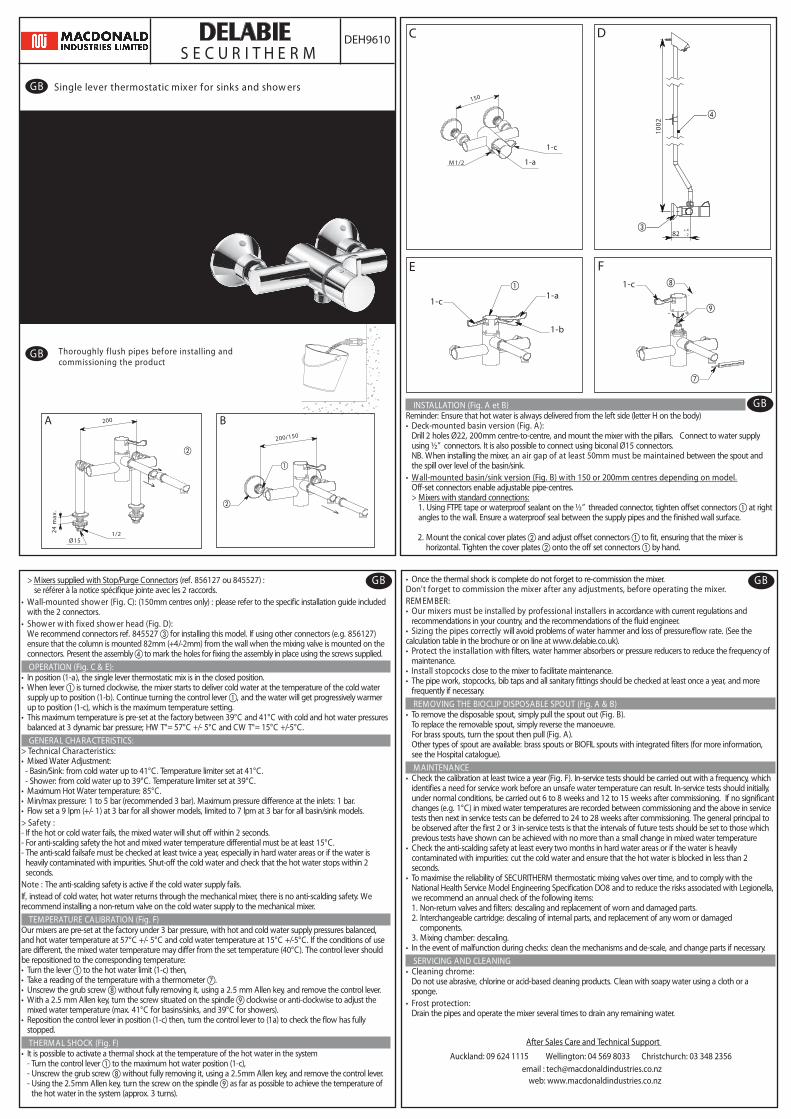
INSTALLATION (Fig. A et B)Reminder: Ensure that hot water is always delivered from the left side (letter H on the body)• Deck-mounted basin version (Fig. A):

Drill 2 holes Ø22, 200mm centre-to-centre, and mount the mixer with the pillars. Connect to water supplyusing ½” connectors. It is also possible to connect using biconal Ø15 connectors.NB. When installing the mixer, an air gap of at least 50mm must be maintained between the spout andthe spill over level of the basin/sink.

• Wall-mounted basin/sink version (Fig. B) w ith 150 or 200mm centres depending on model.Off-set connectors enable adjustable pipe-centres.> Mixers with standard connections:

1. Using FTPE tape or waterproof sealant on the ½” threaded connector, tighten offset connectors at rightangles to the wall. Ensure a waterproof seal between the supply pipes and the finished wall surface.

2. Mount the conical cover plates and adjust offset connectors to fit, ensuring that the mixer ishorizontal. Tighten the cover plates onto the off set connectors by hand.

GB

DEH9610S E C U R I T H E R M

GB Single lever thermostatic mixer for sinks and show ers

GB Thoroughly f lush pipes before installing andcommissioning the product

A 200

24

max

.

Ø151/2

B 200/150

C

150

M 1/2

1-c

1-a

D

100

2

82 +-

42

E F

- +

1-b

1-a1-c

1-c

GB

GB

After Sales Care and Technical Support

Auckland: 09 624 1115 Wellington: 04 569 8033 Christchurch: 03 348 2356email : [email protected]

web: www.macdonaldindustries.co.nz