dehumidifier user manual - allswimltd.com · nf c15.100 pool regulation in volumes 0 and 1, only...
TRANSCRIPT
Dehumidifier User Manual

This manual is an integral part of the product and
must be supplied to the installer and the end user.
The advice included in this manual must be
carefully read as they supply important
indications about safety and maintenance. Keep this
manual in order to consult it if
necessary.
The appliance must be installed according to the
standards in force, by qualified
personnel, this means by personnel having skills to
care of these type of products and heating
installations.
A failing installation can cause damages to persons,
pets or items.
Manufacturer shall not be held responsible for any
failure to comply with saftey and maintenance
instructions set forth in the manual .
When unpacking the unit, check its state.
Before connecting the unit, make sure that the
advice supplied by this manual are in accordance
with the installation and its conditions of use.

Before any servicing, maintenance and repair, switch off the main
supply.
In event of failure or abnormal operation, switch off the unit before
any repair.
Any repair shall be performed by authorized service personnel with
genuine spare parts. The use of non-genuine parts can be harmful to
the unit and to the persons.
In order to ensure a long-lasting efficiency of the unit, it shall be
maintained in accordance with the instructions included in this
manual.
In event of sale or transfer of this unit to another user, make sure this
manual is supplied as well.
This unit must be exclusively used for the use it was designed to. Any
other use shall be considered as improper and hazardous.
In event of damages due either to an improper installation or use or if
the instructions provided or the standards in force are improperly
applied, all manufacturer’s responsibilities will be avoided.
IMPORTANT * CAUTION * IMPORTANT
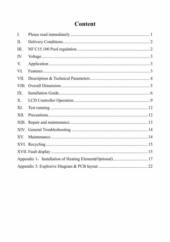
Content
I. Please read immediately .......................................................................... 1
II. Delivery Conditions ................................................................................. 2
III. NF C15.100 Pool regulation .................................................................... 2
IV. Voltage ..................................................................................................... 3
V. Application .............................................................................................. 3
VI. Features .................................................................................................... 3
VII. Description & Technical Parameters........................................................ 4
VIII. Overall Dimension ................................................................................... 5
IX. Installation Guide ..................................................................................... 6
X. LCD Controller Operation ....................................................................... 9
XI. Test running ........................................................................................... 12
XII. Precautions ............................................................................................. 12
XIII. Repair and maintenance ......................................................................... 13
XIV. General Troubleshooting ....................................................................... 14
XV. Maintenance ........................................................................................... 14
XVI. Recycling ............................................................................................... 15
XVII. Fault display .......................................................................................... 15
Appendix 1:Installation of Heating Element(Optional) ................................ 17
Appendix 3: Explosive Diagram & PCB layout .............................................. 22
1
I. Please read immediately
Attention!
A. This machine is an ordinary Dehumidifier and can never be used for
regulating other combustible gas and stale air.
B. The main power switch should be installed out of the reach of children to
avoid dangers caused by their playing with the switch.
C. If it is necessary to remove the machine shell during repair and
maintenance, please make sure that power has been cut off.
Notice for Use
A. The repair and maintenance must be conducted by certified professionals.
The power supply circuit must comply with local standards and please read
instructions carefully.
B. Set appropriate humidity levels to create a comfortable environment.
C. Dust gauze must be cleaned regularly.
D. Please don’t place objects close to the air inlet or outlet which may block
the airflows.
E. In case of a power failure during operation, the device will stop and shall
start automatically after power restoration.
F. Don’t put hands, sticks or other objects into the air inlet and outlet. Don’t
dismantle the running fans of the dust gauze.
G. If any abnormal situation appears, such as strange noises, smell, smoke,
electric leakage, etc., please cut off electricity immediately and contact
local dealer. Do not repair the machine by yourself.
H. The usage or storage of hair gel, paint, oil or other combustible gas or
liquid near the device is forbidden, otherwise there might be fires.
2
II. Delivery Conditions
Every product can be harmed during transportation, even if well packed and
issued, so the transporter should know about these risks that can occur during
transport. A delivery list should be made, in which any damage made during
transportation should be registered. (Confirmation by registered letter to the
carrier within 48 hours).
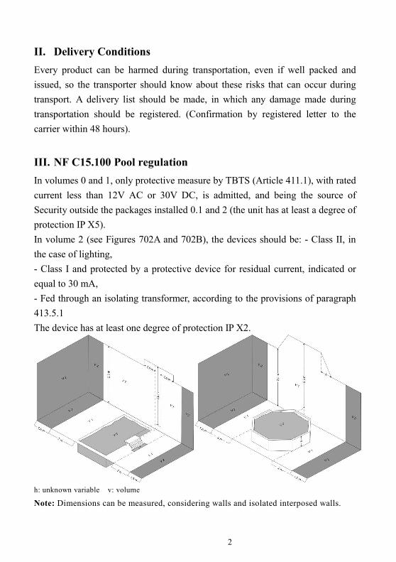
III. NF C15.100 Pool regulation
In volumes 0 and 1, only protective measure by TBTS (Article 411.1), with rated
current less than 12V AC or 30V DC, is admitted, and being the source of
Security outside the packages installed 0.1 and 2 (the unit has at least a degree of
protection IP X5).
In volume 2 (see Figures 702A and 702B), the devices should be: - Class II, in
the case of lighting,
- Class I and protected by a protective device for residual current, indicated or
equal to 30 mA,
- Fed through an isolating transformer, according to the provisions of paragraph
413.5.1
The device has at least one degree of protection IP X2.
h: unknown variable v: volume
Note: Dimensions can be measured, considering walls and isolated interposed walls.
3
IV. Voltage
Before any operation made, the voltage should be checked: it must be the same
that the one indicated on the product and the supply chain.
V. Application
1. Economically and efficiently dehumidification, providing you a cozy
environment.
2. Users can decide an appropriate model by referring to the technical
parameters and under the guidance of professional personnel.
Dehumidifiers of this series have been adjusted to the best of its
performance and they can work properly after wiring and connection of the
drain hose by professionals under the standards.
VI. Features
1. Efficient heat exchanger.
2. Sensitive and accurate digital control of humidity.
3. Environmental friendly refrigerant R410A.
4. Built-in high-voltage, low-voltage and overheat protection system.
5. Ultra-low temperature automatic stop system.
6. Digital automatic defrosting.
7. High-quality compressor of world famous brands.
8. Easy installation and operation.

4
VII. Description & Technical Parameters
Mode Ref. FAI-150-0151 FAI-150-0012 FAI-150-0013
Operating Temperature (℃) 5~38 5~38 5~38
Capacity in (l/h)
(Air 30℃,Humid 70% ) 2.5 3.9 5.0
Heat Recovered (kW) 2.8 4.2 5.5
Rated Power (kW) 1 1.7 2
Rated Current (A) 4.58 7.83 9.15
Max Input Power (kW) 1.2 2.0 2.45
Max Input Current (A) 5.2 9.15 10.8
Power supply 220-240V/1Ph/50Hz
Air flow (m³/h) 800 1000 1200
Electric Heating Optional (kw) 2.0 3.0 3.0
Net Dimension (mm) 855×242×848 1155×280×848 1155×280×848
Net Weight / Gross Weight
(Kgs) 55/67 70/86 75/91
5
1. The rated current of electric heating is 8.7A for FAI-150-0151, 13A for
FAI-150-0012 & FAI-150-0013.
2. Dehumidifying capacity refers to the dehumidifying volume when keeping
the relative humidity at 30℃/70% .
3. Devices of this series can operate normally at the temperature of 5℃~38℃.
Effects cannot be guaranteed if not within this range. Please notice under
different working conditions, the technical parameters of the Dehumidifiers
may vary.
4. Parameters are subject to modification without additional notice in case of
technical upgrade. Please refer to the nameplate at the side of the machine
for more information.
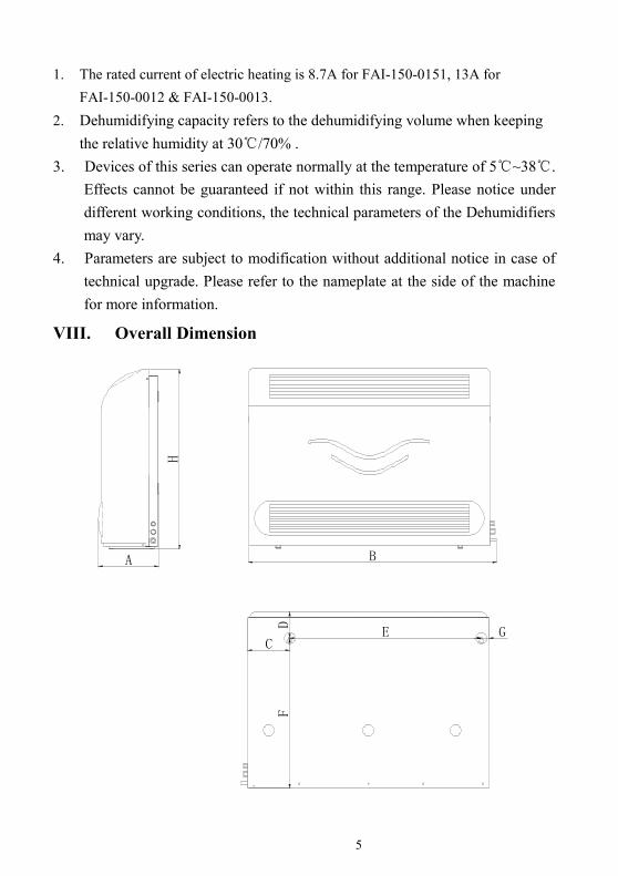
VIII. Overall Dimension
H
A
E GC
FD
B
6
Note: Above dimension is only for reference of professional workers during
installation and arrangement. Due to the continuous improvements, the
products will have phase adjustments without additional notices.
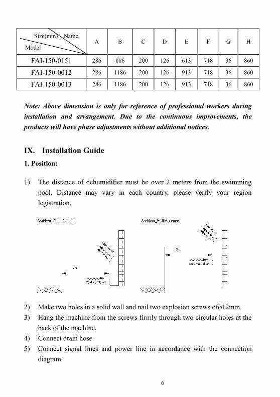
IX. Installation Guide
1. Position:
1) The distance of dehumidifier must be over 2 meters from the swimming
pool. Distance may vary in each country, please verify your region
legistration.
2) Make two holes in a solid wall and nail two explosion screws ofφ12mm.
3) Hang the machine from the screws firmly through two circular holes at the
back of the machine.
4) Connect drain hose.
5) Connect signal lines and power line in accordance with the connection
diagram.
A B C D E F G H
FAI-150-0151 286 886 200 126 613 718 36 860
FAI-150-0012 286 1186 200 126 913 718 36 860
FAI-150-0013 286 1186 200 126 913 718 36 860
Name Size(mm)
Model

7
ABC
A: signal line;
B: power line;
C: water outlet
Note: The figure above is an example and the machine installation and
arrangement is only for reference.
2. Electrical wiring diagram
Power Cord
Breaker/fuse
(Customer prepare)
Earthing
Power Supply
220~240V
50Hz
LN
Note: The Dehumidifier must have a good grounding.
8
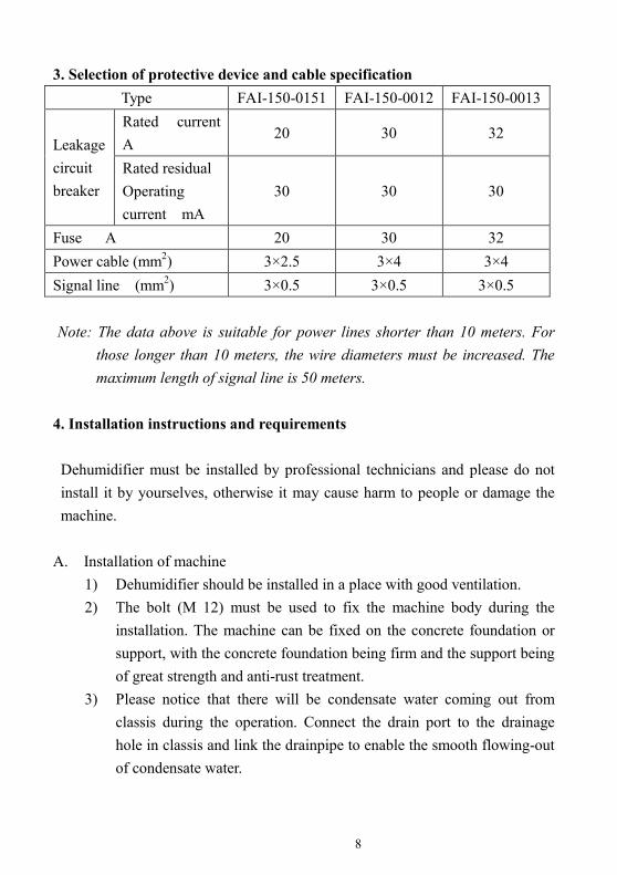
3. Selection of protective device and cable specification
Type FAI-150-0151 FAI-150-0012 FAI-150-0013
Leakage
circuit
breaker
Rated current
A 20 30 32
Rated residual
Operating
current mA
30 30 30
Fuse A 20 30 32
Power cable (mm2) 3×2.5 3×4 3×4
Signal line (mm2) 3×0.5 3×0.5 3×0.5
Note: The data above is suitable for power lines shorter than 10 meters. For
those longer than 10 meters, the wire diameters must be increased. The
maximum length of signal line is 50 meters.
4. Installation instructions and requirements
Dehumidifier must be installed by professional technicians and please do not
install it by yourselves, otherwise it may cause harm to people or damage the
machine.
A. Installation of machine
1) Dehumidifier should be installed in a place with good ventilation.
2) The bolt (M 12) must be used to fix the machine body during the
installation. The machine can be fixed on the concrete foundation or
support, with the concrete foundation being firm and the support being
of great strength and anti-rust treatment.
3) Please notice that there will be condensate water coming out from
classis during the operation. Connect the drain port to the drainage
hole in classis and link the drainpipe to enable the smooth flowing-out
of condensate water.

9
B. Electrical wiring installation
1) The supply voltage should be in line with the rated voltage of this
product.
2) The Dehumidifier must have a good grounding.
3) Wiring must be conducted by professional technicians in accordance
with the standards of circuit diagram.
4) According to related technical standards for electrical equipment set
by local region or country, the electric leakage protection device must
be well set (residual operating current should be less than 30 mA).
5) Power line and signal line arrangement should be tidy and reasonable
without any interference. Depending on environmental conditions
(environmental temperature, direct sunlight, rainwater, grid voltage,
cable length, etc.), the sectional area can be increased.
C. When the wiring construction is finished, the power can be on if there are
no faults after careful checking.
X. LCD Controller Operation
10
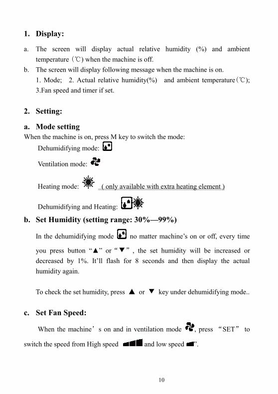
1. Display:
a. The screen will display actual relative humidity (%) and ambient
temperature (℃) when the machine is off.
b. The screen will display following message when the machine is on.
1. Mode; 2. Actual relative humidity(%) and ambient temperature(℃);
3.Fan speed and timer if set.
2. Setting:
a. Mode setting
When the machine is on, press M key to switch the mode:
Dehumidifying mode:
Ventilation mode:
Heating mode: ( only available with extra heating element )
Dehumidifying and Heating:
b. Set Humidity (setting range: 30%—99%)
In the dehumidifying mode no matter machine’s on or off, every time
you press button “▲” or“▼”, the set humidity will be increased or
decreased by 1%. It’ll flash for 8 seconds and then display the actual
humidity again.
To check the set humidity, press ▲ or ▼ key under dehumidifying mode..
c. Set Fan Speed:
When the machine’s on and in ventilation mode , press “SET” to
switch the speed from High speed and low speed ”.
11
d. Timer Setting:
①①①① Set timer
When the device is on, the off time can only be set as 1~12H. When the machine
is off, the on time can only be set as 1~12H.
Press button “ ”: Start the timer setting and change the timer time through
button “▲”and“▼”.
②②②② Cancel the timer
Press to have the time value flashing, then press button “ ”to cancel the
timing and press “ ”to exit.
e. Keypad lock setting
Press “▲”and “▼”simultaneously for three seconds, so as to open/close the
keypad lock .
f. Set Heating ( only available with extra heating element, the setting
range is from 18℃℃℃℃ to 32℃℃℃℃.)
Under heating mode , every time you press ▲ or ▼, the set temperature
can be increased or decreased by 1℃.
To check the set temperature, press ▲ or ▼ and it’ll display the set
temperature.
g. Set Humidity& Heating ( only available with extra heating)
Under mode dehumidifying and heating , press ▲ or ▼ to reach
the set humidity & temperature. Press“ ” to switch on humidity and
temperature.
12
XI. Test running
1. Before usage
A、Check whether the whole machine is place on the ground vertically and
be connected with drain hose.
B、Check whether the electrical wiring has been connected in accordance
with the electrical wiring diagram and whether the earth wire has been
linked reliably.
C、Check whether the power of machine has been cut off.
D、Check whether the set humidity is appropriate.
E、Ensure the air inlet and outlet of the Dehumidifier haven’t been blocked.
2. Test run
A、Users should first switch on the power.
B、As a protection, the device has the start delay function. Fan will start one
minute before compressor.
C、After the dehumidifier starts, check whether there is any strange noise
during operation.
XII. Precautions
1. Notes:
A、Please don’t place any object close to the air inlet or outlet which may
block the airflows. Otherwise, the efficiency may be reduced or the
whole operation of the system may even stop.
B、Do not put hands, sticks or other objects into the air outlet of
Dehumidifier or try to dismantle the grid during operation, or the fan
running at a high speed may cause harm to people.
C、If any abnormal situation appears, such as strange noises, smell, smoke,
electric leakage, etc., please cut off electricity immediately and contact
local dealers. Do not try to repair the machine by yourself.
D、The usage or storage of hair gel, paint, oil or other combustible gas or
liquid near the device is forbidden, otherwise there might be fires.
E、Rinsing the machine directly with water is forbidden.
13
F、Please do not stand on or lean against the machine.
G、Please do not use it to preserve the artworks or academic materials or for
other special purposes, otherwise the quality of restored objects could
not be guaranteed.
H、This machine is only for indoor use. Please do not use it under the
conditions with direct sunlight or wind and rain.
2. Safety rules
A、The main power switch should be installed out of the reach of children to
avoid dangers caused by their playing with the switch.
B、If the electricity fails during the usage, this Dehumidifier will start
automatically after the power restoration. Therefore, please switch off
this machine. Otherwise there might be some accidents.
C、Please cut off the main power in thunderstorm weather, or else the
lightning may damage the machine.
D、Please cut off the main power and drain water out of the machine if it is
not used for a long time.
XIII. Repair and maintenance
1、Before working on the Dehumidifier, please make sure it is disconnected
from the power supply.
2、In seasons when this device is not used, please cut off its power and cover
the machine body with plastic cloth so as to avoid the dust.
3、When cleaning the machine, the domestic neutral detergent on a slightly
damp cloth is recommended, please do not use volatile oil, gasoline, diluent
agent or polishing power for cleaning.
4、Annual check on bolts and cables in recommended, to see if the bolts have
gone loosen, if the wires have been worn out or if the connections are firm.
14
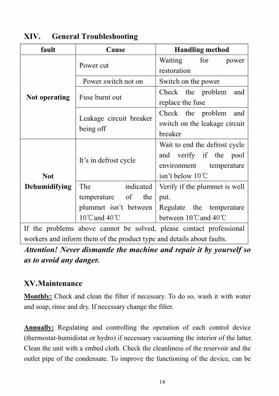
XIV. General Troubleshooting
fault Cause Handling method
Not operating
Power cut Waiting for power
restoration
Power switch not on Switch on the power
Fuse burnt out Check the problem and
replace the fuse
Leakage circuit breaker
being off
Check the problem and
switch on the leakage circuit
breaker
Not
Dehumidifying
It’s in defrost cycle
Wait to end the defrost cycle
and verify if the pool
environment temperature
isn’t below 10℃
The indicated
temperature of the
plummet isn’t between
10℃and 40℃
Verify if the plummet is well
put.
Regulate the temperature
between 10℃and 40℃
If the problems above cannot be solved, please contact professional
workers and inform them of the product type and details about faults.
Attention! Never dismantle the machine and repair it by yourself so
as to avoid any danger.
XV. Maintenance
Monthly: Check and clean the filter if necessary. To do so, wash it with water
and soap, rinse and dry. If necessary change the filter.
Annually: Regulating and controlling the operation of each control device
(thermostat-humidistat or hydro) if necessary vacuuming the interior of the latter.
Clean the unit with a embed cloth. Check the cleanliness of the reservoir and the
outlet pipe of the condensate. To improve the functioning of the device, can be
15
performed a visual inspection of the state of obstruction batteries (evaporator /
condenser and hot water) disassembling the lid (off).
Depending on the state, effective cleaning with the help of a brush on silk and a
vacuum cleaner
XVI. Recycling
In accordance with the European Directive 2002/96/EC, and in order to reach a
number of environmental protection objectives, the following rules must be
obeyed.
These objectives apply to waste from electrical and electronic
equipment (DEEE).
Consumers must return the used products to the collection
points provided.
By enabling the products to be recycled, consumers contribute
to the protection of our environment.
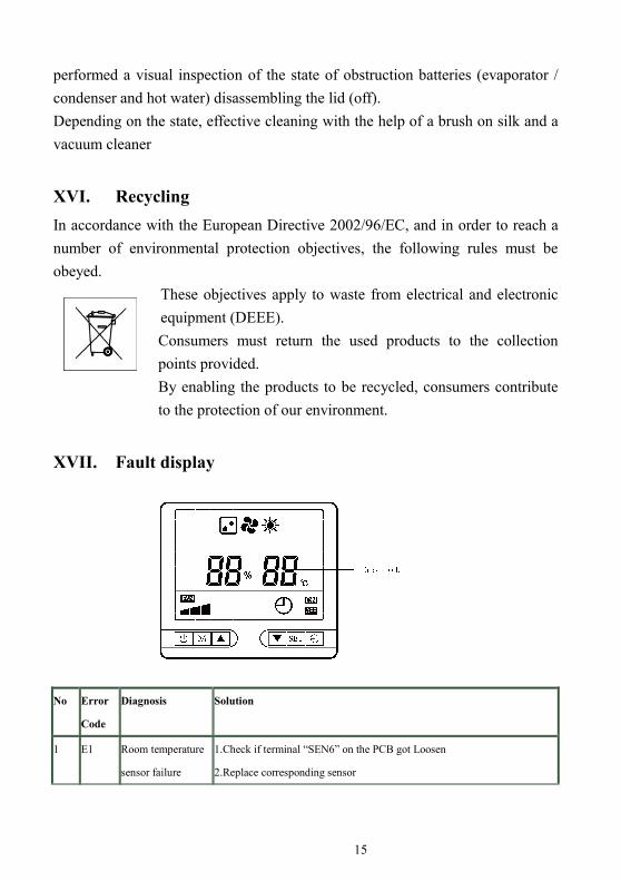
XVII. Fault display
No Error
Code
Diagnosis Solution
1 E1 Room temperature
sensor failure
1.Check if terminal “SEN6” on the PCB got Loosen
2.Replace corresponding sensor
16
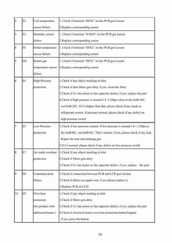
2 E2 Coil temperature
sensor failure
1. Check if terminal “SEN5” on the PCB got Loosen
2.Replace corresponding sensor
3 E3 Humidity sensor
failure
1. Check if terminal “H-SEN” on the PCB got loosen
2.Replace corresponding sensor
4 EF Outlet temperature
sensor failure
1. Check if terminal “SEN2” on the PCB got Loosen
2.Replace corresponding sensor
5 EH Return gas
temperature sensor
failure
1. Check if terminal “SEN1” on the PCB got Loosen
2.Replace corresponding sensor
6 E4 High-Pressure
protection
1.Check if any object stucking at inlet
2.Check if dust filters gets dirty, if yes, clean the filter;
3.Check if it’s fan motor or fan capacitor defect, if yes, replace the part
4.Check if high pressure is around 2.8~3.2Mpa when at dry bulb 30C,
wet bulb 26C. If it’s higher than that, please check if any stuck in
refrigerant system. If pressure normal, please check if any defect on
high pressure switch
7 E5 Low-Pressure
protection
1.Check if low pressure normal. If low pressure is around 1.0~1.2Mpa at
dry bulb30C, wet bulb26C. That’s normal. if not, please check if any leak.
Repair the leak and recharge gas.
2.If it’s normal, please check if any defect on low pressure switch
8 E7 Air outlet overheat
protection
1.Check if any object stucking at inlet
2.Check if filters gets dirty
3.Check if it’s fan motor or fan capacitor defect, if yes, replace the part
9 EE Communication
failure
1.Check if connection between PCB and LCD gets loosen.
2.Check if defect on signal wire, if yes please replace it.
3.Replace PCB or LCD
10 EC Over heat
protection
(for product with
additional heater )
1.Check if any object sucking at inlet
2.Check if filters gets dirty
3.Check if it’s fan motor or fan capacitor defect, if yes, replace the part
4.Check if electrical heater over heat protection buttonTripped.
if yes, press the button.

17
Appendix 1::::Installation of Heating Element(Optional)
Warning : The heating element of dehumidifier must be installed by qualified
electrician.
A.Components List :
1) Heating Element 1 pc
2) Screws 4 pcs
B. Steps
1、 Make sure power supply is cut off before working on the unit. Dismantle the
front panel from the unit.
2、 Place the heating element as shown below:
Signal wire L(red) N ( blue) E (yellow)
Location of heating A hole for the cord to go
Fasten it with 4 screws

18
3、 Wiring of Signal Cable & Power Cable
A、 Wiring Signal Cable:
B、 Wiring Power Cable :
Please refer to the diagram below for connecting power cable. ( “L” port can
be found on PCB )
Open the electrical compartment
Remove the yellow wire Plug in Signal wire Find Signal Wire
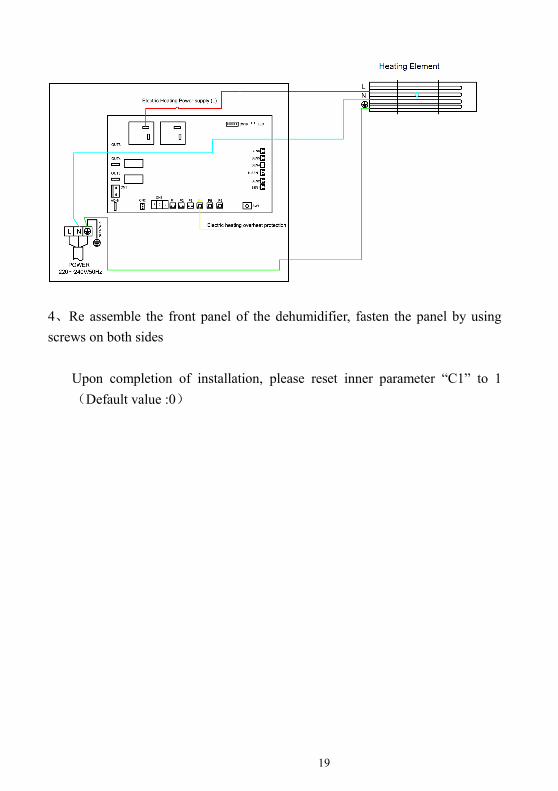
19
4、Re assemble the front panel of the dehumidifier, fasten the panel by using
screws on both sides
Upon completion of installation, please reset inner parameter “C1” to 1
(Default value :0)
20
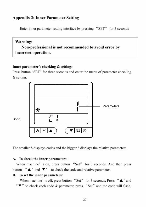
Appendix 2: Inner Parameter Setting
Enter inner parameter setting interface by pressing “SET” for 3 seconds
Inner parameter’s checking & setting::::
Press button “SET” for three seconds and enter the menu of parameter checking
& setting.
The smaller 8 displays codes and the bigger 8 displays the relative parameters.
A. To check the inner parameters:
When machine’s on, press button “Set” for 3 seconds. And then press
button “▲”and ▼” to check the code and relative parameter.
B. To set the inner parameters:
When machine’s off, press button “Set” for 3 seconds; Press “▲”and
“▼”to check each code & parameter, press “Set”and the code will flash,
Warning:
Non-professional is not recommended to avoid error by
incorrect operation.

21
you can press “▲”and“▼” to reset the parameter value. After, press “Set”
to confirm. And press” ”or“ ”to exit。。。。
The parameter table is as follows:
NO. code Parameter
meaning Parameter specification Default value
1 C1 Heating or not 0 no/1 yes 0
2 C2 Coil temperature -20℃~99℃ Measured
value
3 C3 Humidity
compensation -5% ~ 5% 0%
4 C4 Defrosting cycle 15Min~90Min 20Min
5 C5 Defrosting starting
temperature -10℃~10℃ -1℃
6 C6 Defrosting closing
temperature 0℃~15℃ 8℃
7 C7
Maximum
defrosting
time
2Min~12Min 8Min
8 C8
Working state
of draught
fan
0 reaching the set value
and the fan stops/
1 reaching the set value
and the fan operates
with low wind
1
9 C9 Air outlet
temperature -20℃~99℃
Measured
value
10 CA Return gas
temperature -20℃~99℃
Measured
value
11 Cb EXV step number 100~500P Measured
value
12 CC Target superheat
degree -20℃~20℃ 5℃
22
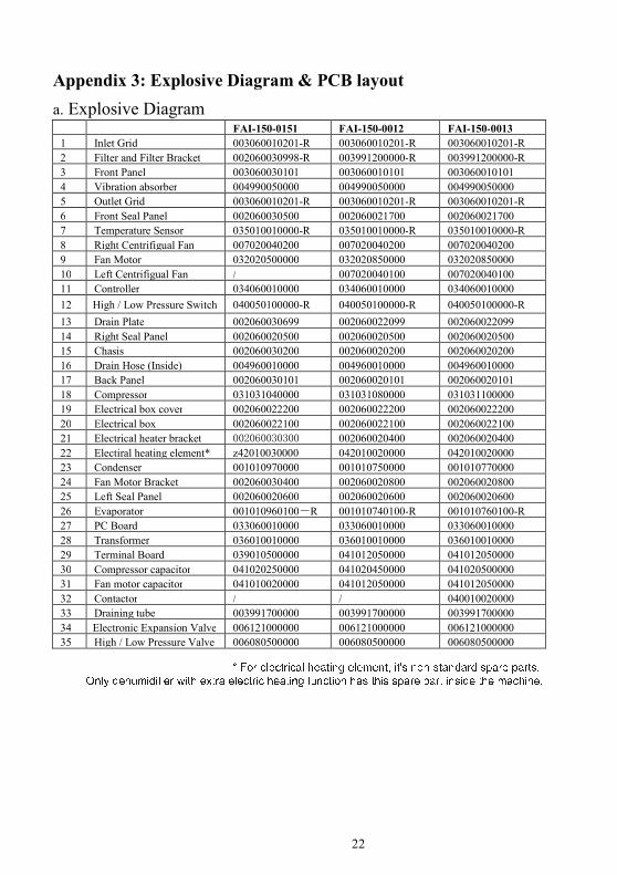
Appendix 3: Explosive Diagram & PCB layout
a. Explosive Diagram
FAI-150-0151 FAI-150-0012 FAI-150-0013
1 Inlet Grid 003060010201-R 003060010201-R 003060010201-R
2 Filter and Filter Bracket 002060030998-R 003991200000-R 003991200000-R
3 Front Panel 003060030101 003060010101 003060010101
4 Vibration absorber 004990050000 004990050000 004990050000
5 Outlet Grid 003060010201-R 003060010201-R 003060010201-R
6 Front Seal Panel 002060030500 002060021700 002060021700
7 Temperature Sensor 035010010000-R 035010010000-R 035010010000-R
8 Right Centrifigual Fan 007020040200 007020040200 007020040200
9 Fan Motor 032020500000 032020850000 032020850000
10 Left Centrifigual Fan / 007020040100 007020040100
11 Controller 034060010000 034060010000 034060010000
12 High / Low Pressure Switch 040050100000-R 040050100000-R 040050100000-R
13 Drain Plate 002060030699 002060022099 002060022099
14 Right Seal Panel 002060020500 002060020500 002060020500
15 Chasis 002060030200 002060020200 002060020200
16 Drain Hose (Inside) 004960010000 004960010000 004960010000
17 Back Panel 002060030101 002060020101 002060020101
18 Compressor 031031040000 031031080000 031031100000
19 Electrical box cover 002060022200 002060022200 002060022200
20 Electrical box 002060022100 002060022100 002060022100
21 Electrical heater bracket 002060030300 002060020400 002060020400
22 Electiral heating element* z42010030000 042010020000 042010020000
23 Condenser 001010970000 001010750000 001010770000
24 Fan Motor Bracket 002060030400 002060020800 002060020800
25 Left Seal Panel 002060020600 002060020600 002060020600
26 Evaporator 001010960100-R 001010740100-R 001010760100-R
27 PC Board 033060010000 033060010000 033060010000
28 Transformer 036010010000 036010010000 036010010000
29 Terminal Board 039010500000 041012050000 041012050000
30 Compressor capacitor 041020250000 041020450000 041020500000
31 Fan motor capacitor 041010020000 041012050000 041012050000
32 Contactor / / 040010020000
33 Draining tube 003991700000 003991700000 003991700000
34 Electronic Expansion Valve 006121000000 006121000000 006121000000
35 High / Low Pressure Valve 006080500000 006080500000 006080500000

23

24
b. PCB layout
Power output (L)
CN19:EEV
Fuse
P1:High Pressure Switch
AC-N
LED terminal
OUT5:Fan(LowSpeed)
CN1:Transformer Input
P4:Electrical heater
OUT4: Fan(High Speed)
CN2:Transformer Output
P2:Low Pressure Switch
Electrical heater power
Compressor output
SEN6:
SEN1: SEN2: H-SEN: SEN5
Version: H6440-140623