deionized, demineralized, or reverse osmosis water...
TRANSCRIPT

Deionized, Demineralized, or Reverse Osmosis Water
“SXDDR” Series Steam Heat Exchanger Humidifiers
Looking for an alternative to electrically generated humidification? Concerned about using chemically treated boiler steam for direct humidification? PURE Humidifier’s “SXDDR” Series Steam Heat Exchanger humidifiers are exactly what you are looking for. Indoor air quality issues concerning the use of boiler steam for direct humidification have resulted in a growing apprehension toward the use of steam injection type humidifiers. The possible carryover of chemical additives and odor created within some boiler systems is being addressed in an effort to improve the indoor air quality for new and existing buildings. The alternative, electric humidifiers, can be prohibitive due to the higher energy costs associated with electrically generated steam versus the typically lower energy cost of boiler steam. For these reasons, PURE has developed the “SXDDR” Series Steam Heat Exchanger humidifier. The “SXDDR” Series humidifiers utilize a stainless steel heat exchanger that allows boiler steam to be used as the heat source for producing steam from tap water. By isolating the boiler steam from the clean tap water, contamination from the boiler is completely eliminated. The steam produced by the “SXDDR” Series humidifier is free from chemical or mineral carry-over, thus providing humidification to meet today's stringent indoor air quality requirements. PURE’s highly efficient heat exchanger produces a greater capacity per unit size than competing designs due to the rectangular transfer tubes, as well as providing simplified maintenance. The “SXDDR” Series humidifier is designed to operate on absolutely pure water, such as deionized, demineralized, or reverse osmosis water.
Since water mineral build-up does not occur with pure water, there is no need for an automatic drain system or cleaning. These units are practically maintenance-free. The water level is maintained with a special float valve (in lieu of the Tri-Probe electronic water controller which is used on the standard water “SX” Series) and a low water float switch is incorporated to provide a low water interlock with the steam control valve. Both floats are protected from water turbulence by an internal baffle. Modulation of the humidifier output is maintained by a high quality control valve, which modulates the steam flow into the heat exchanger. Each humidifier is supplied with a control system mounted in a NEMA-12 enclosure. The control system provides constant monitoring of the water level and safety systems. It also provides a control valve interlock which prevents operation should any of the safety circuits open. When it comes to installation, you have a choice with the “SXDDR” Series Steam Heat Exchanger. The humidifier can be free-standing with a simple (optional) flexible hose connecting the unit to the stainless steel injection tube inserted through the duct wall. You can also mount the unit on the wall with wall brackets, or floor-mounted with support legs (both optional). For mounting under a duct you simply need hangers and support brackets. The versatility of the “SXDDR” Series will allow you to design them into any system simply, efficiently, and reliably.
Sheet No.
SXDDR-1
Our results are comforting
7-15
PURE HUMIDIFIER® and INTAC® are registered trademarks of PURE Humidifier Co.
TM
Sheet No.
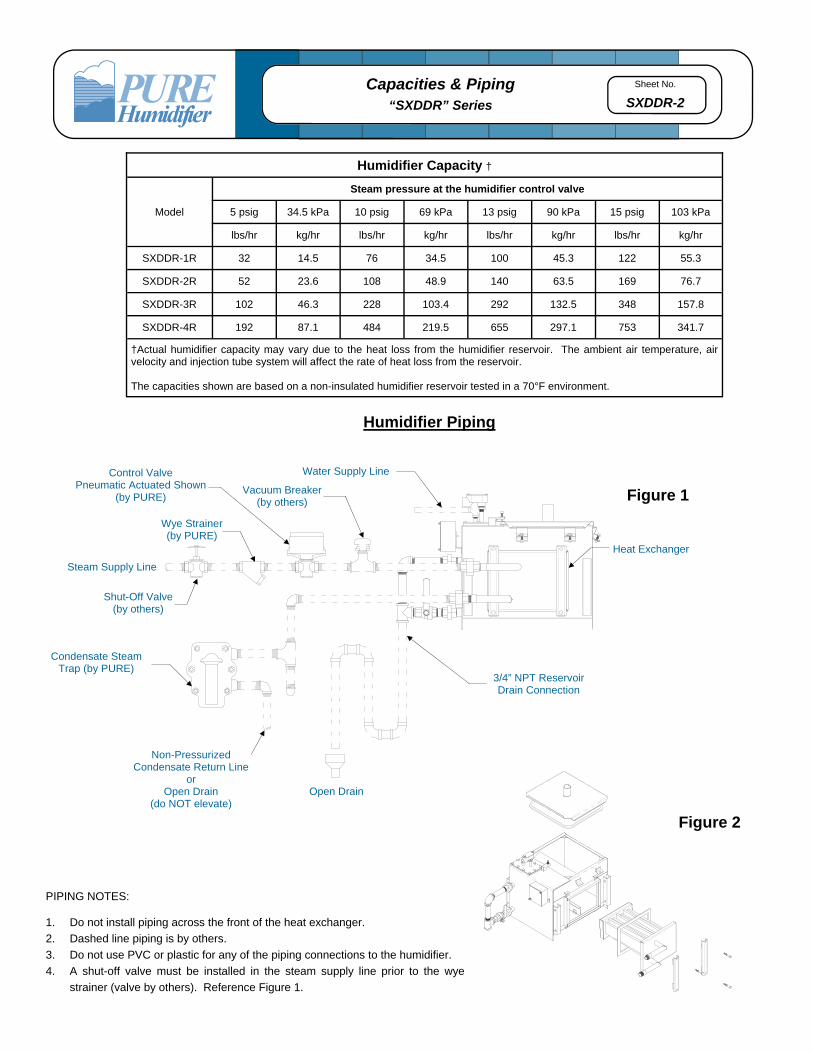
SXDDR-2 Capacities & Piping
“SXDDR” Series
PIPING NOTES: 1. Do not install piping across the front of the heat exchanger.
2. Dashed line piping is by others.
3. Do not use PVC or plastic for any of the piping connections to the humidifier.
4. A shut-off valve must be installed in the steam supply line prior to the wye
strainer (valve by others). Reference Figure 1.
Water Supply Line Control Valve Pneumatic Actuated Shown
(by PURE)
Wye Strainer (by PURE)
Steam Supply Line
Condensate Steam Trap (by PURE)
Non-Pressurized Condensate Return Line
or Open Drain
(do NOT elevate) Open Drain
3/4” NPT Reservoir Drain Connection
Heat Exchanger
Humidifier Piping
Figure 1
Shut-Off Valve (by others)
Vacuum Breaker (by others)
Figure 2
Humidifier Capacity †
Model
Steam pressure at the humidifier control valve
5 psig 34.5 kPa 10 psig 69 kPa 13 psig 90 kPa 15 psig 103 kPa
lbs/hr kg/hr lbs/hr kg/hr lbs/hr kg/hr lbs/hr kg/hr
SXDDR-1R 32 14.5 76 34.5 100 45.3 122 55.3
SXDDR-2R 52 23.6 108 48.9 140 63.5 169 76.7
SXDDR-3R 102 46.3 228 103.4 292 132.5 348 157.8
SXDDR-4R 192 87.1 484 219.5 655 297.1 753 341.7
†Actual humidifier capacity may vary due to the heat loss from the humidifier reservoir. The ambient air temperature, air velocity and injection tube system will affect the rate of heat loss from the reservoir. The capacities shown are based on a non-insulated humidifier reservoir tested in a 70°F environment.

Sheet No.
SXDDR-3 Dimensions, Weights, & Layout
“SXDDR” Series
Unit Dimensions
Model Dim. “A” Dim. “B” Dim. ”C”
Dim. “D” inches cm inches cm inches cm
SXDDR-1R 17.68” 44.9 16.21” 41.2 13.84” 35.2 3/4” NPT 3/4” NPT
SXDDR-2R 25.68” 65.2 16.21” 41.2 13.84” 35.2 3/4” NPT 3/4” NPT
SXDDR-3R 34.18” 86.8 20.46” 52.0 13.84” 35.2 1-1/2” NPT 1-1/2” NPT
SXDDR-4R 54.12” 137.5 29.46” 74.8 13.84” 35.2 2” NPT 2” NPT
*When calculating the total dry weight of the humidifier, the control cabinet weight must be added to the reservoir weight. Due to product improvement, catalog dimensions and specifications are subject to change without notice.
Strainer
16.00” (40.6)
14.00” (35.6)
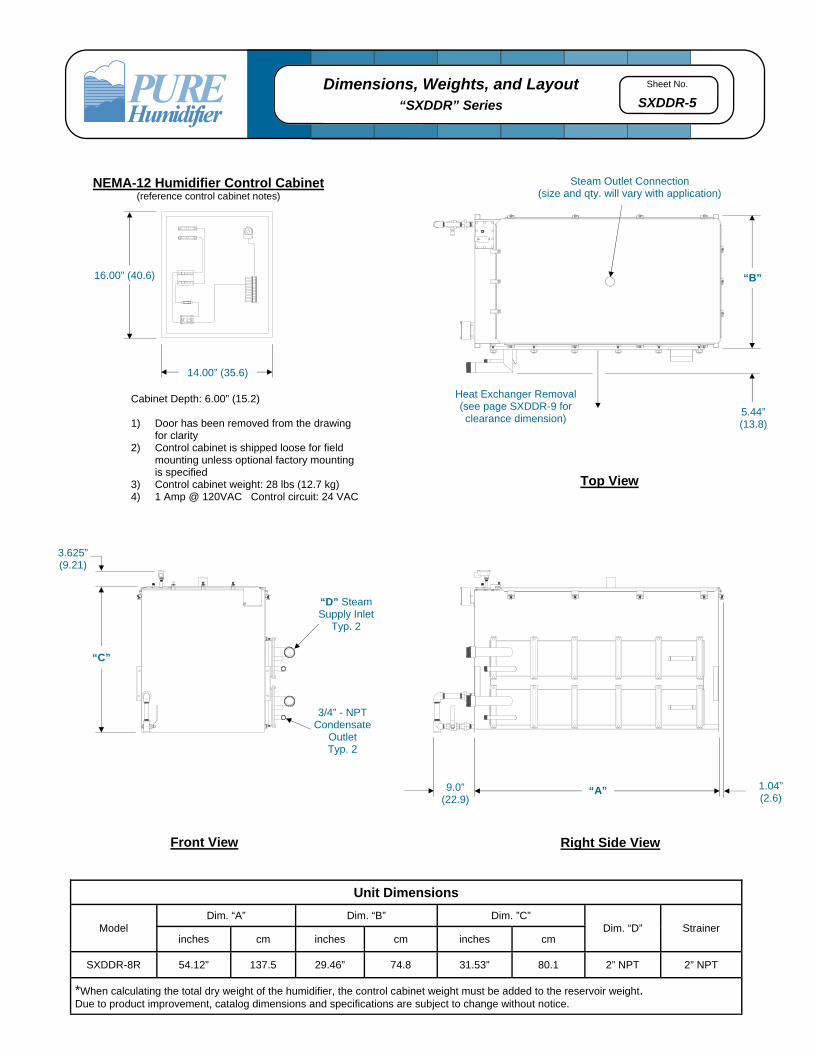
NEMA-12 Humidifier Control Cabinet (reference control cabinet notes)
Cabinet Depth: 6.00” (15.2) 1) Door has been removed from the drawing
for clarity 2) Control cabinet is shipped loose for field
mounting unless optional factory mounting is specified
3) Control cabinet weight: 28 lbs (12.7 kg) 4) 1 Amp @ 120VAC Control circuit: 24 VAC
Steam Outlet Connection (size and qty. will vary with application)
“B”
Top View
3.625” (9.21)
“C”
“D” Steam Supply Inlet
3/4” - NPT Condensate
Outlet
Front View
“A”
Right Side View
9.0” (22.9)
Heat Exchanger Removal (see page SXDDR-9 for clearance dimension)
SXDDR-1R: 3.53” (8.9) SXDDR-2R: 3.53” (8.9) SXDDR-3R: 3.56” (9.0)
SXDDR-4R: 5.44” (13.8)
1.04” (2.6)
Sheet No.
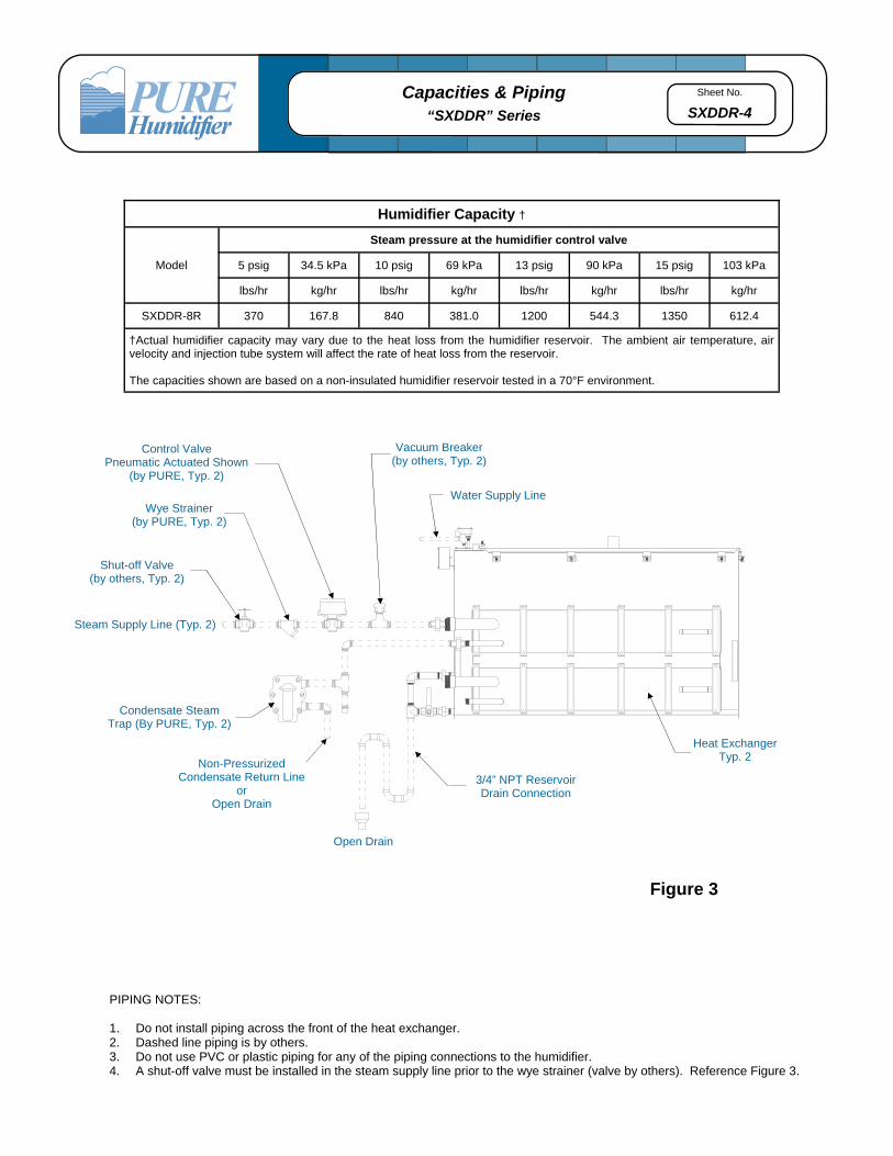
SXDDR-4 Capacities & Piping
“SXDDR” Series
PIPING NOTES: 1. Do not install piping across the front of the heat exchanger. 2. Dashed line piping is by others. 3. Do not use PVC or plastic piping for any of the piping connections to the humidifier. 4. A shut-off valve must be installed in the steam supply line prior to the wye strainer (valve by others). Reference Figure 3.
Figure 3
3/4” NPT Reservoir Drain Connection
Open Drain
Non-Pressurized Condensate Return Line
or Open Drain
Condensate Steam Trap (By PURE, Typ. 2)
Heat Exchanger Typ. 2
Steam Supply Line (Typ. 2)
Shut-off Valve (by others, Typ. 2)
Wye Strainer (by PURE, Typ. 2)
Vacuum Breaker (by others, Typ. 2)
Water Supply Line
Control Valve Pneumatic Actuated Shown
(by PURE, Typ. 2)
Humidifier Capacity †
Model
Steam pressure at the humidifier control valve
5 psig 34.5 kPa 10 psig 69 kPa 13 psig 90 kPa 15 psig 103 kPa
lbs/hr kg/hr lbs/hr kg/hr lbs/hr kg/hr lbs/hr kg/hr
SXDDR-8R 370 167.8 840 381.0 1200 544.3 1350 612.4
†Actual humidifier capacity may vary due to the heat loss from the humidifier reservoir. The ambient air temperature, air velocity and injection tube system will affect the rate of heat loss from the reservoir. The capacities shown are based on a non-insulated humidifier reservoir tested in a 70°F environment.
Sheet No.
SXDDR-5 Dimensions, Weights, and Layout
“SXDDR” Series
Heat Exchanger Removal (see page SXDDR-9 for clearance dimension)
Steam Outlet Connection (size and qty. will vary with application)
“B”
Top View
3.625” (9.21)
“C”
“D” Steam Supply Inlet
Typ. 2
3/4” - NPT Condensate
Outlet Typ. 2
Front View
“A”
Right Side View
16.00” (40.6)
14.00” (35.6)
NEMA-12 Humidifier Control Cabinet (reference control cabinet notes)
9.0” (22.9)
Unit Dimensions
Model Dim. “A” Dim. “B” Dim. ”C”
Dim. “D” Strainer inches cm inches cm inches cm
SXDDR-8R 54.12” 137.5 29.46” 74.8 31.53” 80.1 2” NPT 2” NPT
*When calculating the total dry weight of the humidifier, the control cabinet weight must be added to the reservoir weight. Due to product improvement, catalog dimensions and specifications are subject to change without notice.
Cabinet Depth: 6.00” (15.2) 1) Door has been removed from the drawing
for clarity 2) Control cabinet is shipped loose for field
mounting unless optional factory mounting is specified
3) Control cabinet weight: 28 lbs (12.7 kg) 4) 1 Amp @ 120VAC Control circuit: 24 VAC
5.44” (13.8)
1.04” (2.6)

Sheet No.
SXDDR-6 Capacities & Piping
“SXDDR” Series
PIPING NOTES: 1. Do not install piping across the front of the heat exchanger. 2. Dashed line piping is by others. 3. Do not use PVC or plastic piping for any of the piping connections to the humidifier. 4. A shut-off valve must be installed in the steam supply line prior to the wye strainer (valve by others). Reference Figure 4.
Heat Exchanger Typ. 3
Steam Supply Line (Typ. 3)
Shut-off Valve (by others, Typ. 3)
Wye Strainer (by PURE, Typ. 3)
Control Valve Pneumatic Actuated Shown
(by PURE, Typ. 3)
3/4” NPT Reservoir Drain Connection
Open Drain
Non-Pressurized Condensate Return Line
or Open Drain
Condensate Steam Trap (by PURE, Typ. 3)
Figure 4
Vacuum Breaker (by others, Typ. 3)
Water Supply Line
Humidifier Capacity †
Model
Steam pressure at the humidifier control valve
5 psig 34.5 kPa 10 psig 69 kPa 13 psig 90 kPa 15 psig 103 kPa
lbs/hr kg/hr lbs/hr kg/hr lbs/hr kg/hr lbs/hr kg/hr
SXDDR-12R 560 254.0 1265 573.8 1810 821.0 2035 923.1
†Actual humidifier capacity may vary due to the heat loss from the humidifier reservoir. The ambient air temperature, air velocity and injection tube system will affect the rate of heat loss from the reservoir. The capacities shown are based on a non-insulated humidifier reservoir tested in a 70°F environment.
Sheet No.
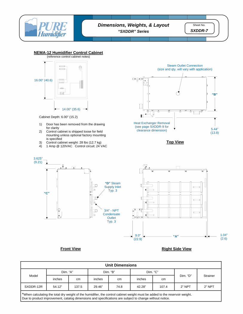
SXDDR-7 Dimensions, Weights, & Layout
“SXDDR” Series
Steam Outlet Connection (size and qty. will vary with application)
Top View
3.625” (9.21)
“C”
“D” Steam Supply Inlet
Typ. 3
3/4” - NPT Condensate
Outlet Typ. 3
Front View
“A”
Right Side View
9.0” (22.9)
“B”
16.00” (40.6)
14.00” (35.6)
NEMA-12 Humidifier Control Cabinet (reference control cabinet notes)
Unit Dimensions
Model Dim. “A” Dim. “B” Dim. ”C”
Dim. “D” Strainer inches cm inches cm inches cm
SXDDR-12R 54.12” 137.5 29.46” 74.8 42.28” 107.4 2” NPT 2” NPT
*When calculating the total dry weight of the humidifier, the control cabinet weight must be added to the reservoir weight. Due to product improvement, catalog dimensions and specifications are subject to change without notice.
Cabinet Depth: 6.00” (15.2) 1) Door has been removed from the drawing
for clarity 2) Control cabinet is shipped loose for field
mounting unless optional factory mounting is specified
3) Control cabinet weight: 28 lbs (12.7 kg) 4) 1 Amp @ 120VAC Control circuit: 24 VAC
Heat Exchanger Removal (see page SXDDR-9 for clearance dimension) 5.44”
(13.8)
1.04” (2.6)

Sheet No.
SXDDR-8 Features
“SXDDR” Series
Features
1. Low Water Float Switch Junction Box 5. Heat Exchanger/Plant Steam Condensate Outlet
2. 1/4” NPT Fill Inlet Connection 6. Pressurized Boiler Steam Inlet
3. Overflow Piping 7. Heat Exchanger
4. 3/4” NPT Ball Valve 8. Humidifier Steam Outlet Connection
1
2
3
4
5
7
6
8
Sheet No.
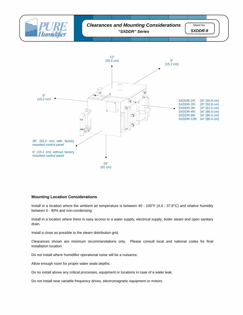
SXDDR-9 Clearances and Mounting Considerations
“SXDDR” Series
Mounting Location Considerations Install in a location where the ambient air temperature is between 40 - 100°F (4.4 - 37.8°C) and relative humidity between 0 - 90% and non-condensing.
Install in a location where there is easy access to a water supply, electrical supply, boiler steam and open sanitary drain.
Install a close as possible to the steam distribution grid.
Clearances shown are minimum recommendations only. Please consult local and national codes for final installation location.
Do not install where humidifier operational noise will be a nuisance.
Allow enough room for proper water seals depths.
Do no install above any critical processes, equipment or locations in case of a water leak.
Do not install near variable frequency drives, electromagnetic equipment or motors.
6” (15.2 cm)
12” (30.5 cm)
6” (15.2 cm)
36” (91.4 cm) with factory mounted control panel 6” (15.2 cm) without factory mounted control panel
24” (61 cm)
SXDDR-1R: 20” (50.8 cm) SXDDR-2R: 20” (50.8 cm) SXDDR-3R: 24” (61.0 cm)SXDDR-4R: 34” (86.4 cm)SXDDR-8R: 34” (86.4 cm)SXDDR-12R: 34” (86.4 cm)

Sheet No.
SXDDR-10 Mounting Applications
“SXDDR” Series
The “SXDDR” Series Electric Humidifier offers a wide variety of mounting applications. If the duct is remote from the humidifier reservoir, free-standing floor support legs or wall brackets (both optional) are available. The humidifier can even be mounted directly within an air handling unit (local codes may require moisture proof construction of certain components). Single or multiple injection tubes can be used to custom fit any duct or air handler size.
Wall Mounting Brackets (optional)
Allows remote mounting of the humidifier reservoir from the duct, or it can be used to mount the humidifier beneath a wall mounted duct.
Free Standing Support Legs (optional)
Allows remote mounting of the humidifier reservoir from the duct. The humidifier is supported 24” from the floor.
Sheet No.
SXDDR-11 Specification Sample
“SXDDR” Series
Humidifier 1. The humidifier shall be steam-heated heat
exchanger type as manufactured by PURE Humidifier Co. of Chaska, Minnesota.
2. The humidifier shall be tested and approved by
ETL/ETL-C Testing Laboratories, Inc. to UL 998 standard.
3. The humidifier shall have an evaporating reservoir
with a gasket sealed cover which is capable of operating at pressures of at least 19” (48 cm W.C.) without steam or water leaks. The reservoir shall be made of type 304 stainless steel with welded joints.
4. The humidifier shall be designed to facilitate easy
removal of the heat exchanger for periodic scale removal and inspection. The cover and heat exchanger shall be secured to the unit by the use of quick release clamps. The heat exchanger shall be removable from the side of the humidifier without disturbing the cover or injection tube system.
5. Humidifier shall be field convertible from a steam
heat exchanger style “SXDDR” humidifier to an electric immersion heater style “ESDDR” humidifier with a simple change of the side entry assembly.
6. A stainless steel float operated low water cut-off
switch shall be provided. The float switch shall provide positive low water cut-off of the humidifier steam supply control valve.
7. A stainless steel float operated water fill valve
mounted on the top near the front shall be provided. The fill valve shall provide automatic refilling of the humidifier reservoir. The water inlet shall be located to allow a minimum water gap of 1-1/2” (3.81 cm).
8. The humidifier shall have a 3/4” (1.9 cm) overflow
pipe to prevent overfilling of the humidifier reservoir.
9. The heat exchanger shall be constructed of type
304 stainless steel rectangular transfer tubes and headers for improved scale removal and cleaning.
10. A normally closed steam control valve with equal
percentage flow characteristics that provides sufficient capacity as required shall be provided. The valve operator (pneumatic modulating standard) or electric modulating (optional) shall be supplied by PURE Humidifier Co..
11. The humidifier shall be supplied with a float and
thermostatic condensate trap and a pipe line wye strainer.
12. The humidifier shall be provided with an ETL/ETL-
C listed JIC NEMA 12 control cabinet, shipped loose (optional factory mounting available). The control cabinet shall be made of 14-gauge steel with ANSI 61 gray polyester powder coating, continuous hinge and oil-resistant gasket. The panel shall include a factory wired sub-panel with control valve interlock, time delay relay, fused control circuit transformer, numbered terminal block, and main power fusing.
13. The control panel shall have a factory wired time
delay relay circuit. The delay circuit shall prevent cycling of the low water interlock circuit due to water fluctuations within the humidifier reservoir.
14. The control system shall maintain humidification
during the fill cycle to maintain a consistent relative humidity.
Sheet No.
SXDDR-12 Options
“SXDDR” Series
Humidifier Insulation. Unit shall be covered (except top cover) with 3/4” (1.9 cm) thick fiberglass duct insulation. Insulation material shall have aluminum foil facing. Mounting Support Legs. Provide support legs made of 1-1/4” x 1-1/4” x 1-1/4” (3.2 cm) angle iron and painted with enamel gray paint. Distance from humidifier bottom to floor shall be 24” (61 cm). Wall Brackets. Provide two wall brackets made of 1-1/4” x 1-1/4” x 1-1/4” (3.2 cm) angle iron and painted with enamel gray paint. Injection Tubes Injection Tube(s) and Flexible Hose. Each unit shall include one or more 10-foot (305 cm) sections of 1-1/2” (3.8 cm) I.D. flexible hose and a 1-1/2” (3.8 cm) O.D. stainless steel injection tube long enough to extend across the duct. Steam ports shall direct steam upward into the airflow. The reservoir cover shall have a matching connection so the flexible hose can be connected with two stainless steel hose clamps. A two-piece duct plate shall be provided to seal the duct opening. Fast-Pac Multiple Tube Assembly. Tube assembly consists of a stainless steel supply/condensate header with a 3/4”-NPT drain connection and horizontal 1-1/2”Ø stainless steel injection tubes. Insty-Pac Tube Assembly. Tube assembly consists of a steam supply/separator header constructed of stainless steel with steam inlet, condensate drain outlet, and steam jacketed injection tubes welded to header. Steam jacketed injection tubes constructed of stainless steel with punched steam ports of the proper size and spacing to deliver the maximum specified capacity. High Efficiency Insulated Tubes. Thermoplastic wrap reduces condensate loss and unwanted heat gain during cooling mode. To Control Cabinet Control Cabinet Factory Mounting. Humidifier control cabinet shall be factory-mounted and wired to the left side of the humidifier. NEMA 4 Control Cabinet. A NEMA 4 weather tight control cabinet shall be substituted for the standard NEMA 12 cabinet. Control Panel Door Lock. Control cabinet shall be provided with a factory-installed key lock on the cabinet door.
Controls and Safety Devides VAV Control. A dual input, single output humidistat shall be supplied to provide a single modulating output signal to the humidifier control cabinet The humidistat shall allow the use of a modulating wall mount sensor and modulating duct high-limit sensor (optional) to control critical variable air volume (VAV) air handling systems. The system shall automatically determine which of the two modulating signals is dominant and slowly reduces the humidifier output capacity, thus preventing over-saturation of the VAV system. Outdoor Air Temperature Setback. Provides automatic reduction of RH set point to prevent condensation on windows during extreme cold weather. Seasonal “End of Use” Humidifier Drain. The humidifier will automatically drain the reservoir after a non-use time period which is field adjustable. Upon receiving a call for humidity, the system automatically refills the reservoir and allows the humidifier to operate in “Normal Mode”. INTAC® Microprocessor Controller. The controller shall be factory-mounted and wired on the electrical compartment door. The INTAC® shall provide 16 character vacuum fluorescent digital display of all functions, high/low humidity deviation alarms, time to service shall be capable of flash memory upgrades through EIA-485 terminal connections. Software updates shall be capable of being provided to customer via e-mail or Internet. Air Flow Proving Switch. A diaphragm operated air flow proving switch with adjustable control range of .05” W.C. to 12.0” W.C. shall be provided for field installation. Switch rating shall be 2.5 amps at 120V. Duct High-Limit. A high-limit humidistat shall be provided for duct installation. The high-limit shall be field set to prevent over saturation within the supply duct. Miscellaneous Accessories DCT-927 Drain Tempering Kit. Provides cold water mixing of the 212°F drain water. Condensate Pump. Used to lift condensate from the humidifier or tube assembly. Outdoor Enclosure. Galvanized steel enclosure with tank freeze protection, control panel mounted, support legs, insulated tank, enclosure heater and hinged access doors. Enclosure is ready to be curb-mounted with the humidifier pre-installed. Ships as one piece. Roof curb is not included.