delco cs-144 modification instructions (non … · delco cs-144 modification instructions...
TRANSCRIPT
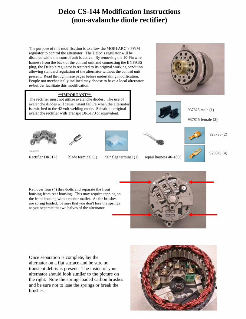
Delco CS-144 Modification Instructions (non-avalanche diode rectifier)
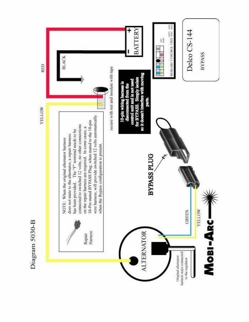
The purpose of this modification is to allow the MOBI-ARC’s PWM regulator to control the alternator. The Delco’s regulator will be disabled while the control unit is active. By removing the 10-Pin wire harness from the back of the control unit and connecting the BYPASS plug, the Delco’s regulator is restored to its original working condition allowing standard regulation of the alternator without the control unit present. Read through these pages before undertaking modification. People not mechanically inclined may choose to have a local alternator re-builder facilitate this modification.
**IMPORTANT** The rectifier must not utilize avalanche diodes. The use of avalanche diodes will cause instant failure when the alternator is switched to the 42 volt welding mode. Substitute original avalanche rectifier with Transpo DR5173 or equivalent.
Rectifier DR5173 blade terminal (1) 90° flag terminal (1) repair harness 46-1803 Remover four (4) thru-bolts and separate the front housing from rear housing. This may require tapping on the front housing with a rubber mallet. As the brushes are spring loaded, be sure that you don't lose the springs as you separate the two halves of the alternator.
Once separation is complete, lay the alternator on a flat surface and be sure no transient debris is present. The inside of your alternator should look similar to the picture on the right. Note the spring- loaded carbon brushes and be sure not to lose the springs or break the brushes.
937825 male (1) 937815 female (2)
925735 (2) 929875 (4)
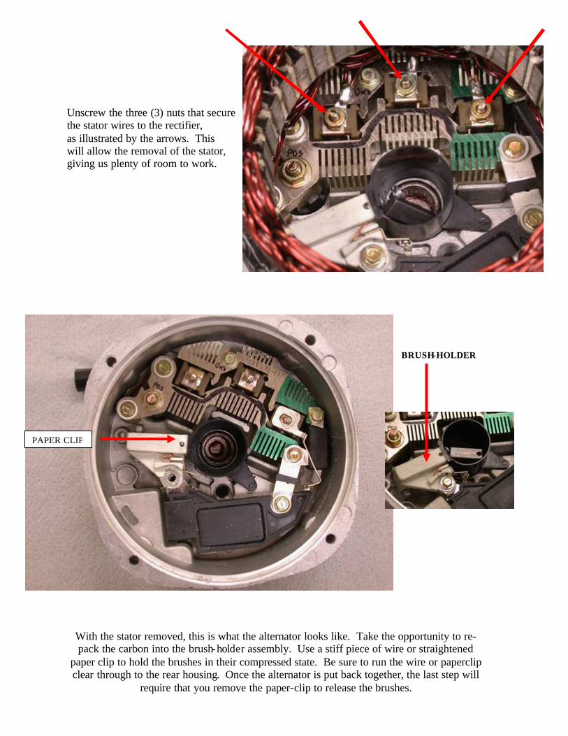
Unscrew the three (3) nuts that secure the stator wires to the rectifier, as illustrated by the arrows. This will allow the removal of the stator, giving us plenty of room to work. BRUSH-HOLDER
With the stator removed, this is what the alternator looks like. Take the opportunity to re-pack the carbon into the brush-holder assembly. Use a stiff piece of wire or straightened
paper clip to hold the brushes in their compressed state. Be sure to run the wire or paperclip clear through to the rear housing. Once the alternator is put back together, the last step will
require that you remove the paper-clip to release the brushes.
PAPER CLIP
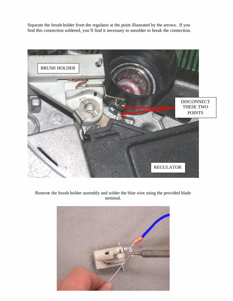
Separate the brush-holder from the regulator at the point illustrated by the arrows. If you find this connection soldered, you’ll find it necessary to unsolder to break the connection.
Remove the brush-holder assembly and solder the blue wire using the provided blade terminal.
REGULATOR
BRUSH HOLDER
DISCONNECT THESE TWO
POINTS
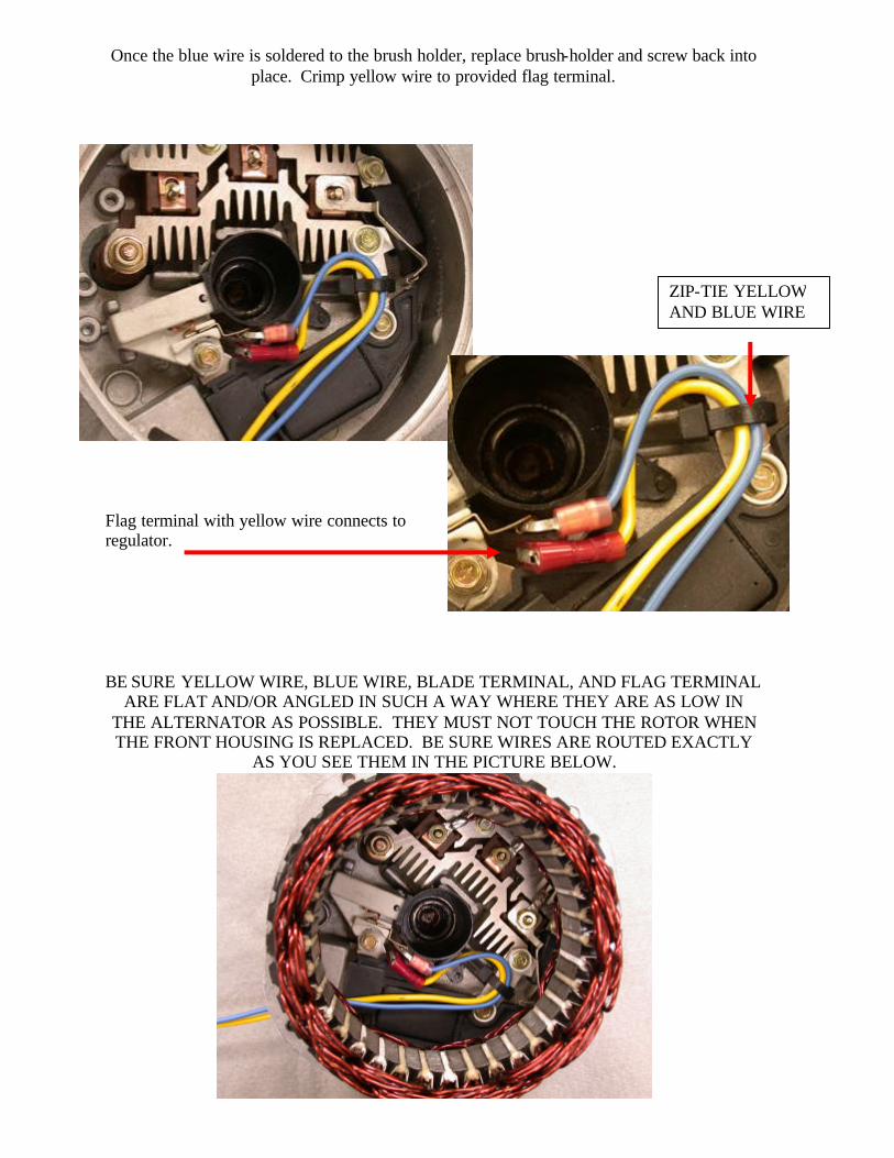
Once the blue wire is soldered to the brush holder, replace brush-holder and screw back into
place. Crimp yellow wire to provided flag terminal.
Flag terminal with yellow wire connects to regulator. BE SURE YELLOW WIRE, BLUE WIRE, BLADE TERMINAL, AND FLAG TERMINAL
ARE FLAT AND/OR ANGLED IN SUCH A WAY WHERE THEY ARE AS LOW IN THE ALTERNATOR AS POSSIBLE. THEY MUST NOT TOUCH THE ROTOR WHEN THE FRONT HOUSING IS REPLACED. BE SURE WIRES ARE ROUTED EXACTLY
AS YOU SEE THEM IN THE PICTURE BELOW.
ZIP-TIE YELLOW AND BLUE WIRE
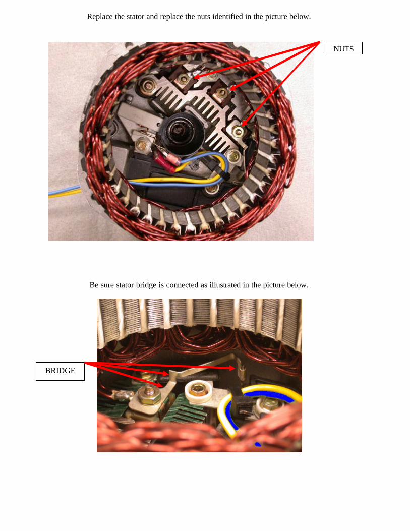
Replace the stator and replace the nuts identified in the picture below.
Be sure stator bridge is connected as illustrated in the picture below.
NUTS
BRIDGE
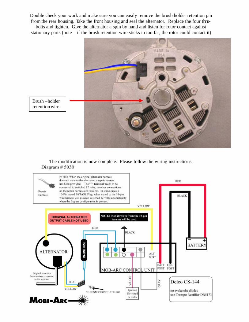
Double check your work and make sure you can easily remove the brush-holder retention pin from the rear housing. Take the front housing and seal the alternator. Replace the four thru-
bolts and tighten. Give the alternator a spin by hand and listen for rotor contact against stationary parts (note—if the brush retention wire sticks in too far, the rotor could contact it)
The modification is now complete. Please follow the wiring instructions.
Brush –holder retention wire