deliverable #3 – midterm report
TRANSCRIPT

Team 11 – NASA/RASC-AL Robo-Ops
FAMU/FSU College of Engineering
Deliverable #3 – Midterm Report
Concept Generation
Faculty Advisors:
Jonathan Clark – Mechanical Engineering
Uwe H. Meyer-Baese – Electrical Engineering
Team Members:
Boris Barreto – Electrical and Computer Engineering
Jason Brown – Mechanical Engineering
Justin Hundeshell – Mechanical Engineering
Linus Nandati – Electrical Engineering
Tsung Lun Yang – Mechanical Engineering
Date: 10/25/2013

Contents Table of Figures ........................................................................................................................................ i
1.0 Introduction ...................................................................................................................................... 1
2.0 Problem Definition ............................................................................................................................ 2
3.0 Background Research and Previous Work .......................................................................................... 3
3.1 Previous Successful Designs from Robo-Ops .................................................................................. 3
3.1.1 – Worchester Polytechnic Institute (WPI) ................................................................................ 3
3.1.2 – California Institute of Technology (Caltech) .......................................................................... 4
3.1.3 – University of Maryland ......................................................................................................... 5
3.1.4 – University of Massachusetts Lowell (U – Mass) ..................................................................... 5
3.2 Last Year’s Design .......................................................................................................................... 6
3.2.1 – Areas of Success ................................................................................................................... 7
3.2.2 – Areas for Improvement ........................................................................................................ 7
3.3 Previous Work by Stride and UPenn ............................................................................................... 7
3.3.1 – Rhex Platform and Locomotion ............................................................................................ 7
3.3.2 – Designed Locomotion with Platform ..................................................................................... 8
4.0 Team Design Objectives ..................................................................................................................... 9
4.1 Multiple Rover System ................................................................................................................... 9
4.1.1 – Pros to Multiple Rover System .............................................................................................. 9
4.1.2 – Challenges with Multiple Rover System ................................................................................ 9
4.2 Single Rover System ....................................................................................................................... 9
4.2.1 – Limitations of Single Rover System ..................................................................................... 10
5.0 Proposed Designs ............................................................................................................................ 11
5.1 – Arm Concepts ........................................................................................................................... 11
5.1.1 – 2 DOF Arm .......................................................................................................................... 11
5.1.2 – 3 DOF Arm with 1 Planar Joint ............................................................................................ 12
5.1.3 – 3 DOF Arm with All Revolute Joints ..................................................................................... 12
5.2 Gripper Concepts ......................................................................................................................... 13
5.2.1 – Scooper Design ................................................................................................................... 13
5.2.2 – Pincer/ Finger Designs ........................................................................................................ 14
5.2.3 – Universal Gripper ............................................................................................................... 14
5.2.4 – Compliant Gripper Mechanism ........................................................................................... 15

5.3 Communications Concepts ........................................................................................................... 16
5.3.1 – Graphical User Interface ..................................................................................................... 16
5.3.2 – Communications and Networking ....................................................................................... 17
5.3.3 – SEM and Locomotion Computers ........................................................................................ 18
5.3.4 – Networks ............................................................................................................................ 19
5.4 Controls Concept Development ................................................................................................... 20
5.4.1 – Turn While Walking ............................................................................................................ 20
5.4.2 – Turn While Climbing ........................................................................................................... 21
5.4.3 – Precision Turns ................................................................................................................... 22
5.4.4 – “Lay-Down-Nudge” Function .............................................................................................. 22
5.4.5 – Control through Gaming Controller .................................................................................... 23
6.0 Decision Matrices ............................................................................................................................ 25
6.1 Arm Selection .............................................................................................................................. 25
6.2 Gripper Selection ......................................................................................................................... 26
7.0 Works Cited ..................................................................................................................................... 27
Appendix ................................................................................................................................................. 1
Product Specs ...................................................................................................................................... 1
Router Specs .................................................................................................................................... 1

Team 11 - i
Table of Figures
Figure 1 -- WPI Arm and Gripper .............................................................................................................. 3
Figure 2 -- Caltech Arm and Gripper CAD Model ...................................................................................... 4
Figure 3 -- Maryland Gripper in CAD and physical form ............................................................................ 5
Figure 4 -- U Mass Arm and Gripper Design ............................................................................................. 6
Figure 5 -- Previous Year's Platform ......................................................................................................... 6
Figure 6 -- Rhex Platform Jumping Up Wall .............................................................................................. 8
Figure 7 -- Climbing Large Obstacles ........................................................................................................ 8
Figure 8 -- 2 DOF Arm Design ................................................................................................................. 11
Figure 9 -- 3 Degree of Freedom with 1 Planar Joint ............................................................................... 12
Figure 10 -- 3 Degree of Freedom Arm with all Revolute Joints .............................................................. 13
Figure 11 -- Scooper Design in Action .................................................................................................... 13
Figure 12 -- CAD Model of a Pincer Design ............................................................................................. 14
Figure 13 -- Universal Gripper Design..................................................................................................... 14
Figure 14 -- FESTO Fin Adaptive Fingers ................................................................................................. 15
Figure 15 -- Cad of Mesh Gripper Design ................................................................................................ 16
Figure 16 -- Previous Year's GUI ............................................................................................................. 17
Figure 17 -- Communication Block Diagram ........................................................................................... 17
Figure 18 -- Communication Between User and Raspberry Pi ................................................................. 18
Figure 19 -- Left: Type G Router Right: Type N Router ........................................................................... 18
Figure 20 -- Verizon 4G USB Stick (left) AT&T 4G USB Stick(right) ........................................................... 19
Figure 21 – Proposed six legged device. The legs are labeled (and will be referenced as) 0 through 5. ... 20
Figure 22 -- Aerial view of the robot to display the leg's labels and their respective groups ................... 20
Figure 23 -- Buehler Clock graph for both sets of legs (Red = A, Black = B) .............................................. 21
Figure 24 -- SpaceHex laying down ........................................................................................................ 23
Figure 25 -- Common Gaming Controllers .............................................................................................. 23

Team 11 - 1
1.0 Introduction
The objective of this project is to build an innovative rover design capable of competing in the 2014 Robo-Ops competition. The robot must be capable of traversing environments similar to those on Mars, it must be teleoperated using wireless communications, and it must be able to selectively pick up brightly colored rocks using an extraction unit. The RASC-AL Robo-Ops competition website provides the following statement outlining the scope of the competition:
“RASC-AL Exploration Robo-Ops Competition (i.e., Robo-Ops) is an engineering competition sponsored by NASA and organized by the National Institute of Aerospace. In this exciting competition, undergraduate and graduate students are invited to create a multi-disciplinary team to build a planetary rover prototype and demonstrate its capabilities to perform a series of competitive tasks in field tests at the NASA Johnson Space Center’s Rock Yard in June 2013.” From this description and from the work of last year’s senior design team, we decided our team’s ambition was to continue to push for innovative solutions to create a rover system. Our team’s goal is to build two smaller rovers, each capable of collecting rock samples. Every team that has competed in the past has used one large robot to collect the samples, mainly because these teams all used wheels and need the large wheel to overcome the obstacles on the environment. Our design would build on the work of last year’s platform, which used six legs to overcome the obstacles it faced, which from last years’ experience and from past research that the legged robot is capable of scaling obstacles larger than the legs.

Team 11 - 2
2.0 Problem Definition
The first problem the team will be addressing is an improved sample extraction module, which will include a means of acquiring discrete rock samples and then storing those samples on the rover platform. Past competitors in the Robo-Ops have found that only three degrees were needed to acquire rock samples with sufficient precision, but these systems were still relatively slow. The team will explore ways to improve the speed and precision of the arm system as well as create a gripper design that will offer precision sample collection while not requiring precision of the robotic arm. The second problem the team will address is the communication system and the user interface for wireless control. Last year, communication issues caused the rover to loose connection during competition, which did not allow the team to finish to course. The communication system also caused significant lag in the video feed and the robot control, which hindered the team’s ability to move the rover precisely. However, the controls the rover had also hindered the user to easily move the rover. It took several mouse clicks and a command input to command the rover to simply move forward. Improved controls and user input will also be explored.
Team 11 - 3
3.0 Background Research and Previous Work The first step toward creating innovative solutions is to understand the state of the art and to examine its strengths and weaknesses. The first area researched past designs in the competition was explored, this gives insight into what designs tend to be successful. Next, the strengths and weaknesses of last year’s platform was examined. Finally, research done in the field of robotics was examined with a focus on legged motion designed by the Stride Lab and University of Pennsylvania.
3.1 Previous Successful Designs from Robo-Ops
3.1.1 – Worchester Polytechnic Institute (WPI)
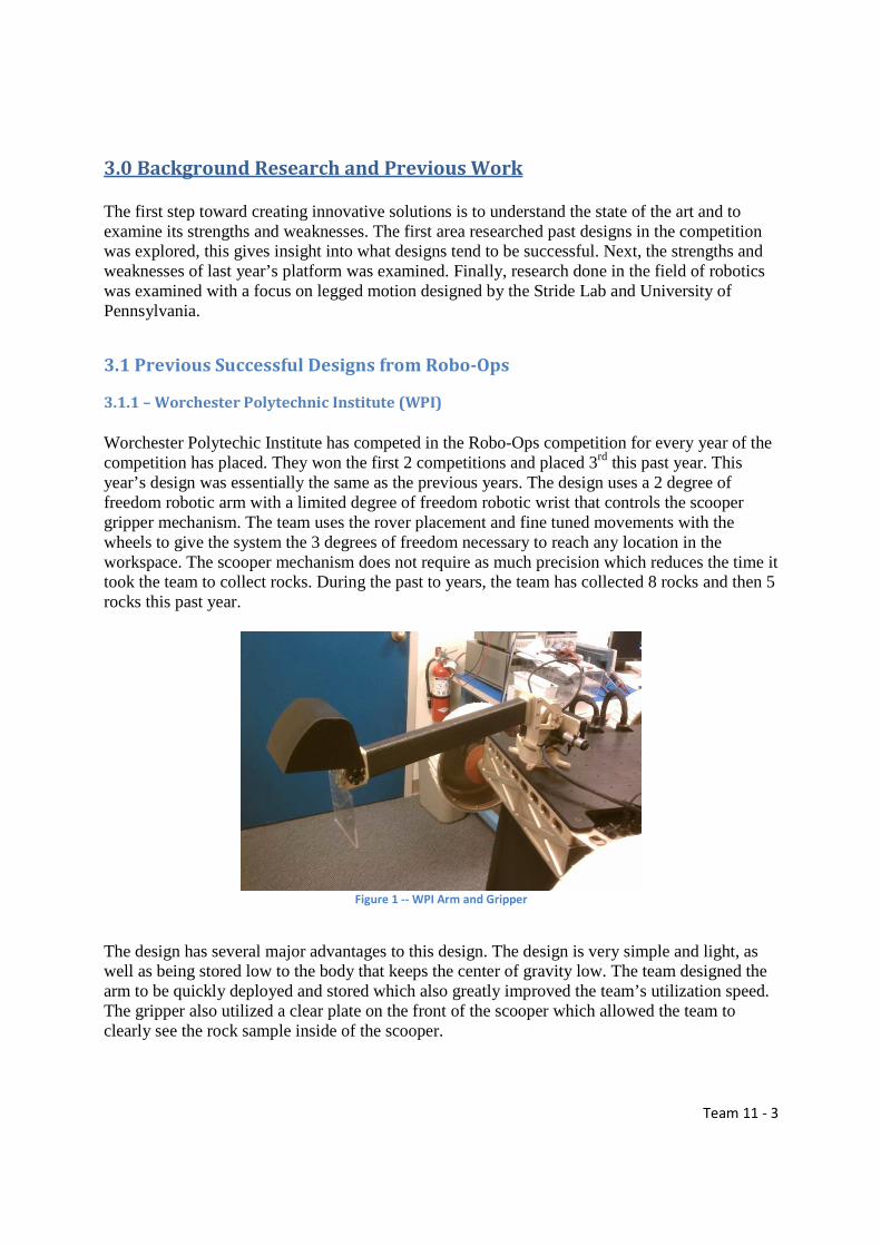
Worchester Polytechic Institute has competed in the Robo-Ops competition for every year of the competition has placed. They won the first 2 competitions and placed 3rd this past year. This year’s design was essentially the same as the previous years. The design uses a 2 degree of freedom robotic arm with a limited degree of freedom robotic wrist that controls the scooper gripper mechanism. The team uses the rover placement and fine tuned movements with the wheels to give the system the 3 degrees of freedom necessary to reach any location in the workspace. The scooper mechanism does not require as much precision which reduces the time it took the team to collect rocks. During the past to years, the team has collected 8 rocks and then 5 rocks this past year.
Figure 1 -- WPI Arm and Gripper
The design has several major advantages to this design. The design is very simple and light, as well as being stored low to the body that keeps the center of gravity low. The team designed the arm to be quickly deployed and stored which also greatly improved the team’s utilization speed. The gripper also utilized a clear plate on the front of the scooper which allowed the team to clearly see the rock sample inside of the scooper.

Team 11 - 4
There are several downsides for this design, specifically with regard to the locomotion system used. This design requires the rover to be able to make small precise motions forward and backwards, which is exceptionally challenging with legged motion. The scooper design also collected sand with the rock samples, which can, over time, weigh down the rover. Finally, the design seemed to take a long time once it was deployed to pick up the rock.
3.1.2 – California Institute of Technology (Caltech)
Cal tech competed in the 2012 Robo-Ops competition and placed 2nd to WPI. The team used a six degree of freedom arm, which was the most of any team in the competition along with a pincer type gripper mounted on the end. The team utilized a camera feed from several camera to ensure the arm was positioned in a way the pincer gripper could grab.
Figure 2 -- Caltech Arm and Gripper CAD Model
The advantage to this design was it allowed a great deal of flexibility in the location of the arm. This meant the gripper could be positioned in many different ways to pick up the same rock, and meant the gripper could pick up a desired rock tucked between 2 other rocks without having to move the other rocks. Finally, the gripper design allowed the team to only pick up rocks without picking up debris or other nearby rocks. The disadvantage of this arm is the advanced control algorithm necessary to move the arm. With a planar arm, if you wish to move the arm in the x direction, you only command 1 motor, but with Cal Tech’s design, it requires 2 or 3 motors to be commanded at the same time to achieve the same motion. Without advanced controls this process would be very slow and cumbersome. The disadvantage of the gripper is it requires very precise positioning the gripper to pick up the sample.

Team 11 - 5
3.1.3 – University of Maryland
The University of Maryland has competed and placed in all of the past three competitions, placing 2nd in the 2013 competition. The team used a four degree of freedom robotic arm with a clamp scoop hybrid.
Figure 3 -- Maryland Gripper in CAD and physical form
The gripper design has the advantage of requiring less precision than the pincer gripper of Caltech, but allowing more precise selection than the WPI design. The team used a soft material with high friction to increase the speed and reduce the precision necessary for the design. By using 4 degrees of freedom, the arm did not require the rover to assist in the location of the gripper. The disadvantages were the gripper did still pick up more than was desired, and the design is heavy which required stronger motors. Like Caltech, it requires advanced controls to achieve planar motion.
3.1.4 – University of Massachusetts Lowell (U – Mass)
The UMass won the 2013 Robo-Ops competition by picking up six rocks. The manipulator system consists of a three DOF arm and gripper. The arm is able to move 120 degrees up and down, and can rotate 300 degrees. The UMass team also used the rover to get close to the rock and to make precise adjustments to the final position. The gripper however is a hybrid scooper and pincer design with some compliance within the gripper. A single stepper motor drives each degree of freedom.

Team 11 - 6
Figure 4 -- U Mass Arm and Gripper Design
The advantages of this design was it did not require advanced controls to operate and ended up being very efficient in picking up rocks. The rover’s wheeled motion gave the design the additional degree of freedom it needed to reach the position of any rock. The gripper design featured a unique fin design which would warp slightly when a rock was grabbed, ensuring more force and friction force was applied to keeping the rock. The disadvantages for this design are similar to those of the WPI team which is that is uses precise motion forward and backwards to collect the rock samples. The gripper design was relatively large, which limited the team from collecting rocks which were next to or between other rocks.
3.2 Last Year’s Design Last year’s design was accepted into the competition and placed 5th overall, which was one of the highest finishes for a team competing for the first time. The team utilized the locomotion of the Rhex platform which was the first rover with legged motion in the competition.
Figure 5 -- Previous Year's Platform
Team 11 - 7
3.2.1 – Areas of Success
The team was able to construct an entire rover from scratch in an entire year, and the rover was one of 5 rovers to complete the entire course. The locomotion system the team utilized allowed them to very effectively traverse the various terrains at the NASA Rock Yard. To make the locomotion possible, the team was able to create a very stable and reliable means of commanding the legs. The rover additionally had a very unique arm mechanism which had only 2 DOF, with the third degree of freedom being controlled by the rover’s body height, which could be controlled with the legs. This lead to much simpler control of the arm, for each degree of freedom was controlled with 1 motor.
3.2.2 – Areas for Improvement
Several areas hurt the team’s performance last year. The first of these was the communication system, which had severe lag and dropped the connection before the end of the competition. The communication system was developed using donated parts, which the team gladly accepted, but were of lesser quality than the team needed to realistically contend in the competition. The second issue was with the vision and the sample extraction module. The team struggled to collect rock samples and only ended up collecting one sample. The team attempted to collect several samples, and had one sample within the gripper, but could not tell it was in the gripper, and therefore dropped it and could not grab it again. The collection system was supposed to utilize a click to grab system, but a last minute hardware issue caused the team to have to use a less effective means of control. Finally, the locomotion system of the past rover, while a solid system and worked very successfully, the team was unable to develop some more advanced locomotion systems which would have aided in the speed with which the team was able to reach the various rock samples.
3.3 Previous Work by Stride and U-Penn
3.3.1 – Rhex Platform and Locomotion
The Rhex platform has multiple different iterations. One of which is developed by Boston Dynamics for military applications. The Boston Dynamics platform is approximately 12.5 kg, can handle slopes of up to 84%, can step over obstacles of 8.5 inches and is teleoperated by the user. This size and capabilities are similar to those needed for the competition. Additionally, Rhex is water resistance and can handle fording streams of 6 inch depth. A second iteration called X Rhex Light (XRL) was developed by the University of Pennsylvania and by the Stride Lab at Florida State University. The platform was used for research to developed walking, turning, jumping and many other control algorithms. The platform is approximately 10 kg, and has been developed with very unique controls.

Team 11 - 8
3.3.2 – Designed Locomotion with Platform
The focus of XRL was to research the controls and algorithms of the Rhex type platform. The team will be attempting to replicate some of these locomotion types. The first the team will be working to develop is turning while walking. For a wheeled platform, turning while moving forward is simple, have the outside go faster than the inside. However, it is not that simple for legged motion, for three legs need to be on the ground at the same time for stability. To achieve a turn while walking, the outside legs must be on the ground for longer than the inside wheels. Some of the other research does was to determine the optimal gate for running and walking. For the current SpaceHex platform, running is not possible, but for a platform the size of XRL, running and jumping algorithms would greatly increase the rover’s functionality.
Figure 6 -- Rhex Platform Jumping Up Wall
Other processes were developed to allow XRL to actually climb vertical walls and overcome obstacles much larger than the legs. Figure 1 shows the vertical jump and climbing ability of XRL while figure 2 shows XRL climbing up an obstacle that could not be overcome with standard walking motion.
Figure 7 -- Climbing Large Obstacles
Team 11 - 9
4.0 Team Design Objectives
4.1 Multiple Rover System
The team is planning on building a multiple rover system which will have several smaller rovers which are all capable of collecting rock samples. This is unique and have never been seen before at competition, and would provide some significant advantages. There are some challenges to achieving the multiple rover system however.
4.1.1 – Pros to Multiple Rover System
There are several major advantages to building several rovers, approximately half the size of the SpaceHex platform used last year. The first of these is the ability to seek multiple rocks samples at the same time. Every team in the past has had to collect one rock, then move to the next rock. Teams get a bonus for collecting rocks in each area, and therefore being able to have 2 rovers would be a significant advantage. The second major advantage is weight. While two rovers might seem to be heavier, scaling down the motors, batteries, and body reduces the weight significantly. Even if the rovers are 20kg each, the package would still be lighter than the 45 kg of last year’s competition. The final advantage is the ability of the smaller rovers to utilize the unique locomotion systems developed for the Rhex platforms. The smaller rovers would be able to move faster than the large rover because they would be able to run instead of just walking. This additional advantage on top of getting 2 rocks at the same time would vastly improve the teams sample collection.
4.1.2 – Challenges with Multiple Rover System
The multiple rover system has several challenges that must be overcome in order for the system to become reality. The first of these is the expense of building several rovers from scratch. The rover last year cost the team approximately $16,000 which they received in the form of parts and sponsorship. The multiple rover platform would be just as expensive, and possibly more expensive. The cost would likely not be reduced significantly if we used part from last year’s design, for the smaller rovers have different specifications. The second challenge is finding a way for one or two users to control both of the rovers as well as communicating the commands and receiving the video feed. Last year’s team had issues with commanding and communicating with one rover, and this could only get harder with more rovers.
4.2 Single Rover System
While the team thinks the challenges with the multiple rover system make it worth overcoming the challenges, some of the challenges, specifically the expense of the system, might force the

Team 11 - 10
team to reuse the past year’s platform and work to significantly improve the system. The area’s for improvement have already been discussed in section 3.4.2. There are limitations though of how much can be improved.
4.2.1 – Limitations of Single Rover System
There are some limitations to how much the previous design can be improved. The controls system is currently being updated to include several of the locomotion schemes seen with the Rhex platform including turn while walking. The second limitation is the current weight of the rover. The old platform was at the edge of the allowable weight range. While the arm was heavy at 10 kg, the rest of the body is still 35 kg, and is heavy compared to the wheeled platforms. This does not leave much weight to be creative with the design.

Team 11 - 11
5.0 Proposed Designs
5.1 – Arm Concepts
5.1.1 – 2 DOF Arm
The first arm concept is to improve upon last year’s design, a planar two degree of freedom arm. The design would need to be reduced and a more advanced wrist would be developed with the arm. The rover can have very precise control over it Z position making this arm simple and easy.
Figure 8 -- 2 DOF Arm Design
The advantages of this design were described by last year’s team, but will be explored again for comparison. The system requires the control of only 2 motors, and the control over the rover itself. The thought was also that by having fewer motors and systems, the overall weight would be reduced, and would impact the cost and reliability of the system. The final thought was that the arm remaining close to the body would keep the platform more stable. The desired advantages turned out to be some of the arms shortcomings. The control did turn out to be significantly easier, and allowed the team to develop a click to grab routine where the user could click on the GUI and the robot would move the arm into position to pick up the sample. This routine was not tested in competition because an encoder failed the night before competition. The from the hardware desire, the arm could not fit into the competition dimensions with the arm remaining planar. A innovative rail follower was devised, but forced the arm into the air, which then hurt the center of gravity and the deployment speed. Finally, to achieve the reach desired, a

Team 11 - 12
large linear actuator was needed and then forced the rest of the system to be bigger and heavier than originally thought.
5.1.2 – 3 DOF Arm with 1 Planar Joint
Three degree of freedom arm concepts were then explored. The first of these was this arm design which has 2 revolute joints and a planar joint to extend the arm. This design would be similar to WPI’s design with the addition of a linear actuator instead of a rigid arm.
Figure 9 -- 3 Degree of Freedom with 1 Planar Joint
The advantages to this design is it requires less control than an arm like Caltech’s or Maryland’s, but still give the necessary degrees of freedom to reach most rocks without the rover needing to move. The design could still stay close to the body and keep the center of gravity low. The disadvantages for this design include the weight of the system which would likely by higher to include an linear actuator. The revolute joint would need to be designed to withstand the weight and the motors controlling the degrees of freedom would need to be stronger.
5.1.3 – 3 DOF Arm with All Revolute Joints
The final design explored is a three degree of freedom arm with all revolute joints. The design would consist of a 2 degree of freedom “shoulder” joint, and a 1 degree of freedom “elbow. The current concept is to include a 1 degree of freedom wrist, but this would depend on the gripper concept chosen.

Team 11 - 13
Figure 10 -- 3 Degree of Freedom Arm with all Revolute Joints
The advantages of this concept is the flexibility in it use and in its flexibility in placement on the rover. It could be placed on top of or in front of the rover without any difference in functionality. Additionally, the storage compartment could be placed in any location which is convenient. Finally, it can be very compact and utilize very lightweight materials and still be strong enough and have the desired range. The disadvantage is the advanced control necessary to utilize such a design. For it to be user friendly to use, the arm would need to have some form of automation, or at least control mapped from the x y z frame to the motor.
5.2 Gripper Concepts
5.2.1 – Scooper Design
The first design discussed was a scooper designed gripper. Scoop is defined by Merriam Webster as “something that is shaped like a bowl or bucket and used to pick up and move things”. Essentially, it uses a distinctive shape and gravity to collect large quantities of material. It does not require as much precision as the pincer design which we will talk through next.
Figure 11 -- Scooper Design in Action

Team 11 - 14
5.2.2 – Pincer/ Finger Designs
Pincer/finger grippers use the same technique as the human had to grab and secure small objects. The pincer normally has two fingers which can move in toward an object or release away from the object, and uses a constant force on the object to keep it secured. It is very good at picking up discrete objects, but needs to be placed precisely for the object to be secured.
Figure 12 -- CAD Model of a Pincer Design
5.2.3 – Universal Gripper
Some more recent gripper research has gone into attempting to develop a gripper which has the ability to easily grab a discrete object. This has led to the development of universal grippers which utilize a conformable material to grasp an object. The gripper shown below in Figure # consists of a balloon filled with ground coffee. The balloon is pressed onto the object desired, and then a vacuum pump evacuates air from the balloon, causing the coffee grounds to jam against each other, forming a ‘rigid’ gripper.
Figure 13 -- Universal Gripper Design

Team 11 - 15
5.2.4 – Compliant Gripper Mechanism
The combinations of the previous designs lead to very interesting concepts. The first of these is compliant fingers which combines the universal gripper with the pincer gripper. Compliant finger grippers need to be precise in their implementation, but require less precision than rigid fingers. They can reach and grab discrete objects in confined spaces, however the precision required to use them is still very high. There are a few finger ideas on the board, 2 pronged, which is small and can reach most everything but needs to squeeze the rock and get a good grip as it’s only touching the rock in two places, or 3 pronged, which would hold the rock very stable but may not be able to get access to 3 different sides of the rock. The FESTO Fin Adaptive Finger (right) has gained our curiosity as its shape conforms to object it is grabbing and is delicate enough to pick up an egg. The second idea for fingers are rake-like, skinny tendrils on the fingers allow the fingers to close around the rocks shape to have greater contact area.
Figure 14 -- FESTO Fin Adaptive Fingers
By combining the universal gripper, with a scoop design, along with some elements of the pincer, you can come up with a mesh gripper. The mesh gripper consists of two clamps that have a mesh screen in their center, then became an elastic mesh grip which will be more versatile and have a higher friction coefficient. With the bottom support was removed to create an upside-down U structure so we can get the mesh as close to the ground as possible. This mesh gripper clamps onto the rock and it conforms to the unique shape of the rock.

Team 11 - 16
Figure 15 -- Cad of Mesh Gripper Design
5.3 Communications Concepts
Last year’s design utilized Verizon 3G coverage to communicate with the platform. This was advantageous considering the fact that a tower is very near to the competition site. A “mission control” center was established in Tallahassee where the users controlled the rover. The design was simple. Mission control consisted of a user working with the GUI to operate the robot. The GUI would be on a laptop. Using a 3G USB Card, the laptop would communicate with a router on board the rover. The router has a USB port, which is helpful in communications. Last year’s operators plugged in a Verizon 3G card in the router as well. The on-rover router would communicate with the Raspberry Pi computers, thus linking the user to the rover.
5.3.1 – Graphical User Interface
The Graphical User Interface (GUI) is a custom computer application which aims to greatly simplify the operation of the rover through integration of information display, in the form of video feeds and sensor data, and rover control. In essence, it gives the user a tool for controlling the rover. In last year’s design, the GUI was written in the C# program language. Below is an image of the objective of the design:

Team 11 - 17
Figure 16 -- Previous Year's GUI
The GUI was operational, but many aspects will be changed in order to make the GUI more user friendly. For one thing, the user would have to input the number of steps and the direction that the rover should proceed. The process was very cumbersome, especially if the user needed the rover to move to a specific spot. As the rover will be competing with other rovers to pick up the most rocks, creating a GUI that allows the user to interact more freely with the rover would be much more efficient. There were also locomotion concerns, as was discussed earlier, as the rover could not turn while walking. So the GUI only has the controls Forward, Reverse, turn-Left, and turn-Right. Our goal is to implement an Xbox or PlayStation controller allowing the user 360 degrees of control, with the ability to change direction while moving. We wish to eliminate the need to enter the number of steps prior to moving. A simple push of the joystick will command the rover to move.
5.3.2 – Communications and Networking
To establish communication between the cameras and computing systems on the rover and the Mission Control server located at the college detailed networking protocol is desired. The figure below displays the design of the network. The blocks on the right represent (top to bottom) the rover arm, locomotion and cameras.
Figure 17 -- Communication Block Diagram

Team 11 - 18
As the above figure shows, communications via SSH (Secure Shell) were established between the on-rover computers and the mission control computer; communication via HTTP (Hypertext Transfer Protocol) was used to link the cameras to mission control. In last year’s case, both the mission control computer and networked hardware on the rover are behind NAT (Network Address Translation) firewalls. The NAT firewall prevents all incoming connections to all the devices.
5.3.3 – SEM and Locomotion Computers
In last year’s design, the communications system was put together in more haste than what would have been ideal. For one, the mission control operated from a student’s apartment. Also, the on-rover router used was a G-type router leading to limited bandwidth. Looking at last year’s issues, a lack of bandwidth may have contributed to the issues of last year’s team, such as lagging and dropped communications. Additionally, the video feed would be impaired by a low-resolution, which normally would be used in cases where the bandwidth was limited. To counteract these issues, a higher grade router will be used. Last year’s router, the TP-Link TL-MR3430 (pictured below) was a fine router for home usage, but a higher grade router would do the project well.
Figure 18 -- Communication Between User and Raspberry Pi
Figure 19 -- Left: Type G Router Right: Type N Router

Team 11 - 19
The router’s function was so that the user could communicate with the Raspberry Pi computers. Raspberry Pi’s are now 3G compatible, but using a router makes the connection between the user and the Pi computers more secure. As will be discussed below, we plan on using a 4G network for this year’s design. The TP-LINK SafeStream TL-ER6020 Gigabit Dual-WAN VPN Router (pictured below) is an ideal router to use with a 4G card. It is a next generation, the N-type. It creates a VPN (Virtual Private Network) thus adding more security by securing an IP address, and preventing interference from other addresses. Additionally, the router is much more powerful, with enough bandwidth to spare.
5.3.4 – Networks
In order to further improve the design, some other minor modifications are necessary. This year’s team will make the mission control router the DNS-enabled router. Last year, the team did not take care to make sure only one router was DNS-enabled. Also, some issues arose that were out of the control of the team. The team relied on Verizon’s 3G network as there was a tower near the site. Ironically, the 3G network had issues on the day of the competition. This year’s team plans to incorporate 4G. While some 3G networks are faster than 4G networks, within a carrier, 4G always trumps 3G. For instance, Verizon 3G is faster than MetroPCS 4G, but Verizon’s 4G is faster than its 3G. Verizon’s 3G network is actually relatively poor when compared to other network speeds with download and upload speeds 1.05 and 0.75 Megabits per second (Mbps) respectively However, Verizon’s 4G network showcases a vast improvement over its predecessor with download and upload speeds of 7.35 and 5.86 Mbps respectively. These speeds are bested only by AT&T’s network. Verizon’s network is advantageous in part due to the tower nearby the competition site. We plan on using 2 Verizon 4G USB sticks, 1 on the rover, and 1 at mission control.
Figure 20 -- Verizon 4G USB Stick (left) AT&T 4G USB Stick(right)
We are going to strive for as much redundancy with the platform due to some issues that arose last year. The Verizon Network was down that day, much to the team’s dismay. Using AT&T’s network is an option we are strongly considering in case Verizon’s network fails this year. We will use the same communications model as with the 4G, but we will not utilize it unless Verizon’s network fails. This practice ensures we are not sending conflicting commands to the
Team 11 - 20
rover, which may cause serious ramifications, such as the robot’s malfunction. Since Houston is a major city, using AT&T may very well be the way to go.
5.4 Controls Concept Development
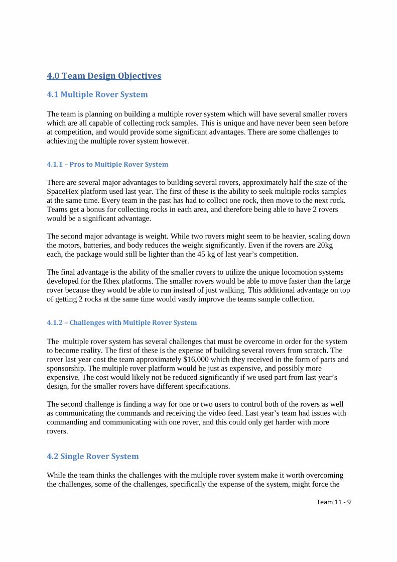
Last year’s six legged design had the necessary tools for traversing the competition grounds, but there is still work to be done to allow the rover to move more freely and efficiently through the different terrains. The rover was only able to turn while stationary, and walk directly forwards/backwards.
Figure 21 – Proposed six legged device. The legs are labeled (and will be referenced as) 0 through 5.
This year, the team will be attempting to implement a turn while walking function, a turn while climbing function, a more precise turning function, and a “lay-down-nudge” function. These will all be controlled by a wireless controller instead of the GUI interface which was used last year.
5.4.1 – Turn While Walking
Front
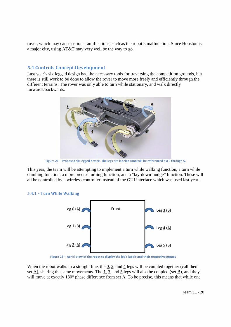
When the robot walks in a straight line, the 0, 2, and 4 legs will be coupled together (call them set A), sharing the same movements. The 1, 3, and 5 legs will also be coupled (set B), and they will move at exactly 180° phase difference from set A. To be precise, this means that while one
Leg 0 (A) Leg 3 (B)
Leg 1 (B) Leg 4 (A)
Leg 2 (A) Leg 5 (B)
Figure 22 -- Aerial view of the robot to display the leg's labels and their respective groups

Team 11 - 21
set is pointing directly downward, in its peak contact with the ground, the other set will be directly upright, at its highest point. 2π
0
4
3
4 T
To understand the locomotion further, one must understand the Buehler clock. The Buehler clock describes the relationship between the speed of the leg and its location in its rotation. When any given set of legs are on the ground, they must move slower than when they are in the air, so that the other legs can “catch” the robot right as they are leaving the ground stage. Figure 13 shows this relationship. The slope of the lines describes the speed of the legs rotation, the y axis describes the location in the legs rotation, and the x axis describes time. Notice that the legs change speeds at T/4 and (3T)/4. Notice that in this image, both sets of legs start and end at 0 and 2π respectively. Now that walk is understood, turn while walking must be implemented. One’s immediate response to implementing turn while walking is to increase the speed of one side of the legs and thus create a turn. This design was considered but quickly failed when it was hypothesized and proven that the rover would simply fall over, since the legs would lose their coupling over time. The next idea was to adjust the phase at which the left legs differ from the right legs. For example, put leg 1 20° ahead of legs 3 and 5, while simultaneously putting leg 4 20° behind legs 0 and 2. This will cause the left legs (the ones that are ahead) to hit the ground slightly before the right legs leave the ground. For the second that the legs are together on the floor, there will be a slight turning motion to the right, and then the robot will continue to move forward once the left legs catch up (at which point the other set of legs will have lifted into the air).
5.4.2 – Turn While Climbing
Turning while climbing is very similar to turning while walking, but with an extra hurdle. Walking on flat land is simple, if the legs are in phase, they will move forward with no problem. However, on a small hill, the rover has a tendency to turn with the hill as it climbs. To adjust for this, a separate hill climbing function was created and is currently functioning on the rover.
This function must now be added to. Just as with the turn while walking, the team wants to make the robot more agile when on a hill. It seems likely that adjusting the phase just as was done in
Figure 23 -- Buehler Clock graph for both sets of legs (Red = A, Black = B)

Team 11 - 22
the turn while walking will resolve this issue and become extremely helpful in climbing hills quickly.
5.4.3 – Precision Turns
Currently, precision turns are working, but not for slight turns. The reason for this is that the robot is defined to work in “steps”. Every time the precision turn function is called, a number of steps must be input to the rover. The robot then takes this many “steps” to that direction, without moving forwards or backwards. Currently, it takes the robot six steps to completely turn around an approximate 180°. This means that for each step that the robot is instructed to take; it is currently turning roughly 30°. This is great for a machine which wants to turn quickly, but extremely non-ideal for one which wants to pick up rocks, and precisely position a gripper to easily pick up those rocks. The turn must be worked on so that it can be more precise for angles lower than 30°. To do this, the robot will have to be programmed to be able to take a “half step”, or maybe even a “quarter step”. Currently, a step is counted every single time a set of legs gets off of the floor, so every time a set of legs makes a full rotation, it is two steps. This means that part of the problem comes from the fact that the legs are long. Downsizing to the smaller machines should serve as a partial solution to the problem, but it might not be enough. On a more core level, however, there are two options to create a precise precision turn. Steps will either be redefined in the current function or a new function will have to be written which can input fractional steps, and thus allow the rover to stop its rotation mid-step.
5.4.4 – “Lay-Down-Nudge” Function
A new idea which is going to be attempted this year is to implement a nudge while laid down function. Last year’s team discovered that the most efficient way for the rover to pick up objects is to lay it down and then operate the arm and gripper. This causes a problem, however, because if the robot lies down and is slightly out of position, a complete repositioning of the machine is required. This means it has to completely stand up and relocate to a hopefully better position.

Team 11 - 23
Figure 24 -- SpaceHex laying down
To combat this, a “nudge” function will be implemented. The rover will very quickly push the legs into the ground, creating lift and hopefully pushing the robot backwards. This could also be implemented to just the left or right legs, which will allow the robot to turn slightly even though it is lying down. The advantages to this could be incredibly evident, since the team which collects the most rocks gets the most points. Last year’s team was only able to collect one rock because of how hard it was to correctly position the rover over a rock.
5.4.5 – Control through Gaming Controller
Using a GUI (graphical user interface) was reasonable for last year’s machine, but this year a more user-friendly interface is going to be implemented. All options are being considered, so long as it is a wireless controller. Some ideas have been discussed, but the most common ones are gaming controllers.
Figure 25 -- Common Gaming Controllers

Team 11 - 24
The advantage to these types of controllers is extremely evident. There are so many ways which these controllers could be of use to the rover. First and foremost, there must be a way to control the locomotion of the machine, while simultaneously controlling the arm of the machine. The current machine is designed to operate in locomotion until a rock is spotted and gone after. The machine lies down before the arm is activated. This is a good design, and allows for the machine to perform both tasks. On startup, the controller can be in “locomotion mode.” In this mode, the left analog sticks will be used to control the robots forward and backward motion, while the right analog stick is going to control the left and right motion. This will allow the controller to control speed, direction, and intensity of every motion the machine makes. When the robot enters “lie down mode” (i.e. after pressing ‘X’), the robot can use the joysticks to control the arm. The vast numbers of buttons can allow the robot to perform different tasks such as “drop arm” and “nudge backwards”. The biggest problem with this design is that the current code for the rover isn’t dynamic enough for this control mechanism. The robot moves with each command, and does not allow any commands to be input until the command finishes its execution. A controller is constantly changing commands (with a joystick). This can be worked around by making the code more dynamic and allowing commands to change throughout. This is usually easily accomplished by enabling interrupts in the code, which will be attempted.
Team 11 - 25
6.0 Decision Matrices After considering the designs above, the team created the following decision matrices to make our selection.
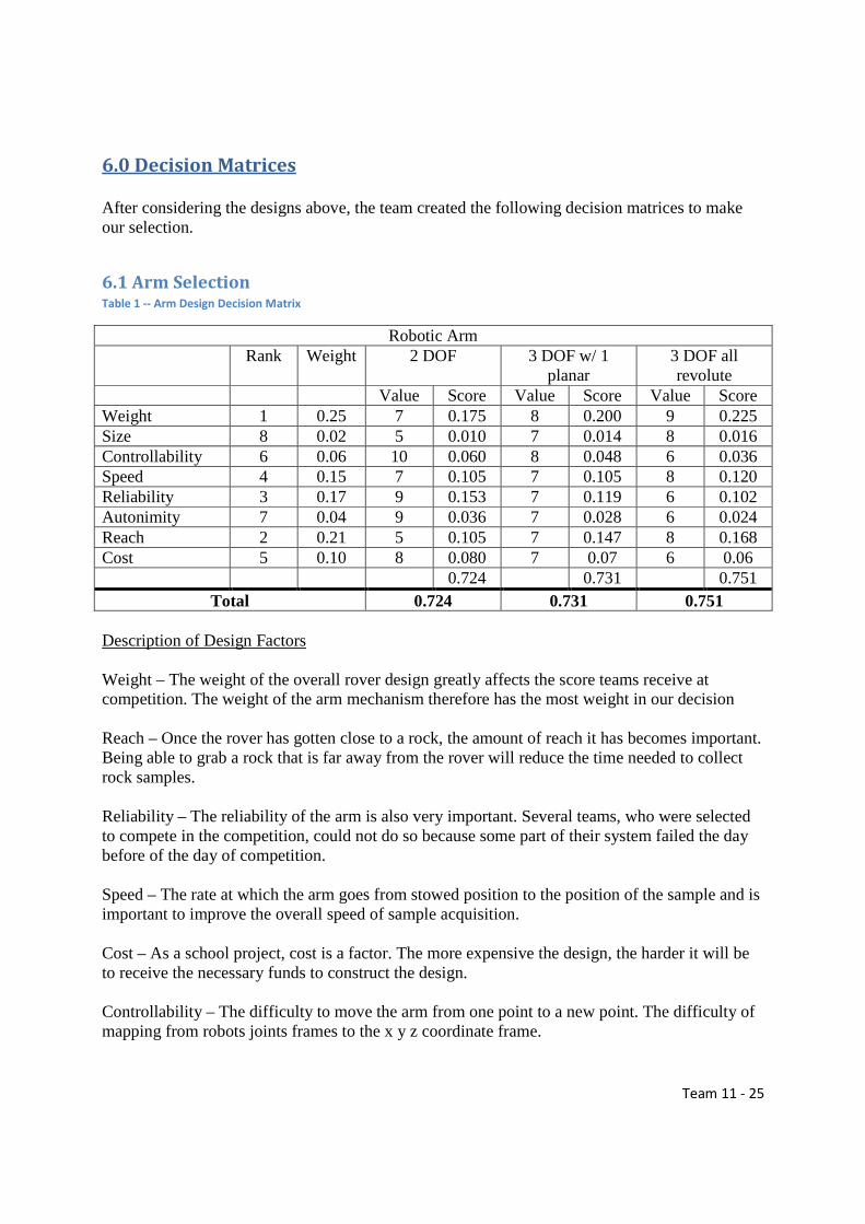
6.1 Arm Selection Table 1 -- Arm Design Decision Matrix
Robotic Arm Rank Weight 2 DOF 3 DOF w/ 1
planar 3 DOF all revolute
Value Score Value Score Value Score Weight 1 0.25 7 0.175 8 0.200 9 0.225 Size 8 0.02 5 0.010 7 0.014 8 0.016 Controllability 6 0.06 10 0.060 8 0.048 6 0.036 Speed 4 0.15 7 0.105 7 0.105 8 0.120 Reliability 3 0.17 9 0.153 7 0.119 6 0.102 Autonimity 7 0.04 9 0.036 7 0.028 6 0.024 Reach 2 0.21 5 0.105 7 0.147 8 0.168 Cost 5 0.10 8 0.080 7 0.07 6 0.06 0.724 0.731 0.751
Total 0.724 0.731 0.751 Description of Design Factors Weight – The weight of the overall rover design greatly affects the score teams receive at competition. The weight of the arm mechanism therefore has the most weight in our decision Reach – Once the rover has gotten close to a rock, the amount of reach it has becomes important. Being able to grab a rock that is far away from the rover will reduce the time needed to collect rock samples. Reliability – The reliability of the arm is also very important. Several teams, who were selected to compete in the competition, could not do so because some part of their system failed the day before of the day of competition. Speed – The rate at which the arm goes from stowed position to the position of the sample and is important to improve the overall speed of sample acquisition. Cost – As a school project, cost is a factor. The more expensive the design, the harder it will be to receive the necessary funds to construct the design. Controllability – The difficulty to move the arm from one point to a new point. The difficulty of mapping from robots joints frames to the x y z coordinate frame.
Team 11 - 26
Autonimity – The difficulty in making the system almost completely autonomous. With Autonomous control, less work will be required to command the arm and acquire the rock samples, saving time on collection. Size – The overall size of the design needs to fit within certain size requirements. The robotic arm cannot exceed these specifications, but as long as the design does, the arm’s size is not critical.
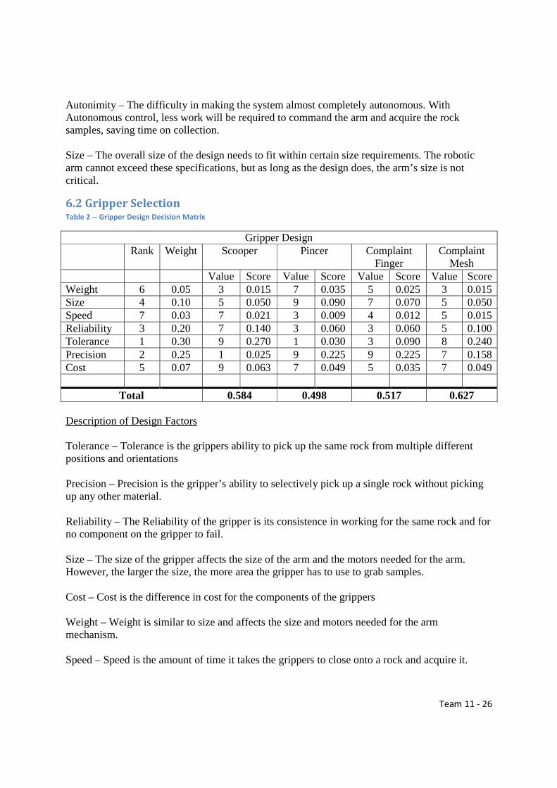
6.2 Gripper Selection Table 2 -- Gripper Design Decision Matrix
Gripper Design Rank Weight Scooper Pincer Complaint
Finger Complaint
Mesh Value Score Value Score Value Score Value Score Weight 6 0.05 3 0.015 7 0.035 5 0.025 3 0.015 Size 4 0.10 5 0.050 9 0.090 7 0.070 5 0.050 Speed 7 0.03 7 0.021 3 0.009 4 0.012 5 0.015 Reliability 3 0.20 7 0.140 3 0.060 3 0.060 5 0.100 Tolerance 1 0.30 9 0.270 1 0.030 3 0.090 8 0.240 Precision 2 0.25 1 0.025 9 0.225 9 0.225 7 0.158 Cost 5 0.07 9 0.063 7 0.049 5 0.035 7 0.049
Total 0.584 0.498 0.517 0.627 Description of Design Factors Tolerance – Tolerance is the grippers ability to pick up the same rock from multiple different positions and orientations Precision – Precision is the gripper’s ability to selectively pick up a single rock without picking up any other material. Reliability – The Reliability of the gripper is its consistence in working for the same rock and for no component on the gripper to fail. Size – The size of the gripper affects the size of the arm and the motors needed for the arm. However, the larger the size, the more area the gripper has to use to grab samples. Cost – Cost is the difference in cost for the components of the grippers Weight – Weight is similar to size and affects the size and motors needed for the arm mechanism. Speed – Speed is the amount of time it takes the grippers to close onto a rock and acquire it.

Team 11 - 27
7.0 Works Cited http://www.bostondynamics.com/img/RHex%20Datasheet%20v1_0.pdf http://www.123rf.com/photo_14201603_hydraulic-excavator-loading-dirt-load-from-its-scoop-into-an-articulated-dump-truck-on-a-constructio.html http://mekabot.com/products/compliant-gripper/ http://spectrum.ieee.org/automaton/robotics/robotics-hardware/upenn-kodlab-rhex-legged-robot-leaping http://www.engadget.com/2013/07/25/rhex-robot-uses-leaping-ability-to-do-parkour/ http://nia-cms.nianet.org/RoboOps/Presentations/UML-Rover-Hawks-Final-Report.aspx

Team 11 - 1
Appendix
Gantt Chart

Team 11 - 1
Product Specs
Router Specs
TP-Link TL-MR3430
HARDWARE FEATURES
Standards and Protocols IEEE 802.3, 802.3u, 802.3x,
TCP/IP, DHCP, ICMP, NAT, PPPoE
Interface 1 10/100Mbps WAN port, 4 10/100Mbps LAN ports (Auto
Negotiation/Auto MDI/MDIX)
Network Media
10BASE-T: UTP category 3, 4, 5 cable (maximum 100m)
EIA/TIA-568 100Ω STP (maximum 100m)
100BASE-TX: UTP category 5, 5e cable (maximum 100m)
EIA/TIA-568 100Ω STP (maximum 100m)
Button Reset Button
External Power Supply 9VDC 0.6A
Dimensions (W X D X H) 5.9*3.9*1.1 in. (150*100*28 mm)
Power Supply Max. 1.7W (With Power Adapter)
SOFTWARE FEATURES
Basic Function
DHCP Server, DHCP Client,
MAC Address Modify/Clone,
VPN Pass-through
Port Setting LAN and WAN Port Setting
Port Forwarding Virtual Server, Special Application
Static Routing, DMZ Host, UPnP
Firewall Security
Firewall Rules Setting,
MAC Address Filtering,
Domain Name Filtering,
IP/MAC Address Binding,

Team 11 - 2
SOFTWARE FEATURES
Ignore Ping Packet From WAN Port
System Function Remote Management, Flow Statistics
System Log, TFTP Upgrade
OTHERS
Certification FCC, CE, RoHS
Package Contents
TL-R402M
Resource CD
Power Adapter
RJ-45 Ethernet Cable
Quick installation Guide
System Requirements Microsoft® Windows® 98SE, NT, 2000, XP, Vista™ or Windows 7,
MAC® OS, NetWare®, UNIX® or Linux.
Environment
Operating Temperature: 0~40 (32~104)
Storage Temperature: -40~70 (-40~158)
Operating Humidity: 10%~90% non-condensing
Storage Humidity: 5%~90% non-condensing
TP-LINK SafeStream TL-ER6020 Gigabit Dual-WAN VPN Router
HARDWARE FEATURES
Standards and Protocols
IEEE 802.3, IEEE802.3u, IEEE802.3ab
TCP/IP, DHCP, ICMP, NAT, PPPoE, SNTP, HTTP, DNS, IPsec, PPTP,
L2TP
Interface
2 Gigabit WAN ports
2 Gigabit LAN ports
1 Gigabit LAN/DMZ port
1 Console Port (RJ-45 On RS232)
Network Media 10BASE-T: UTP category 3, 4, 5 cable (Max 100m)

Team 11 - 3
HARDWARE FEATURES
EIA/TIA-568 100Ω STP (Max 100m)
100BASE-TX: UTP category 5, 5e cable (Max 100m)
EIA/TIA-568 100Ω STP (Max 100m)
1000BASE-T: UTP category 5, 5e, 6 cable (Max 100m)
Flash 16MB
DRAM DDRII 128MB
LED PWR, SYS, Link/Act, Speed, DMZ
Button Reset Button
Dimensions (W X D X H) 11.6*7.1*1.7in. (294*180*44mm)
13-inch Standard Rack-Mount Width, 1U Height
Fan Quantity Fanless
Power Supply Internal Universal Power Supply
AC100-240V~ 50/60Hz Input
PERFORMANCE
Concurrent Session 30000
NAT Throughput 180Mbps
IPsec VPN Throughput (3DES) 80Mbps
BASIC FUNCTIONS
DHCP DHCP Server/Client
DHCP Reservation
MAC Clone Modify WAN/LAN/DMZ MAC Address
Switch Setting
Port Mirror
Rate Control
Port Config
Port VLAN
WAN Connection Type Dynamic IP, Static IP, PPPoE, PPTP, L2TP, Dual Access, BigPond
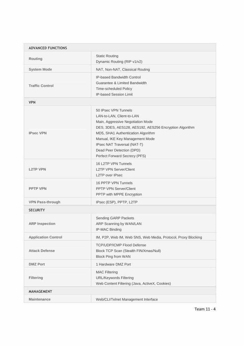
ADVANCED FUNCTIONS
Load Balance
Intelligent Load Balance
Policy Routing
Protocol Binding
Link Backup (Timing, Failover)
Online Detection
NAT
One-to-One NAT
Multi-nets NAT
Virtual Server, DMZ Host, Port Triggering, UPnP
FTP/H.323/SIP/IPsec/PPTP ALG
Team 11 - 4
ADVANCED FUNCTIONS
Routing Static Routing
Dynamic Routing (RIP v1/v2)
System Mode NAT, Non-NAT, Classical Routing
Traffic Control
IP-based Bandwidth Control
Guarantee & Limited Bandwidth
Time-scheduled Policy
IP-based Session Limit
VPN
IPsec VPN
50 IPsec VPN Tunnels
LAN-to-LAN, Client-to-LAN
Main, Aggressive Negotiation Mode
DES, 3DES, AES128, AES192, AES256 Encryption Algorithm
MD5, SHA1 Authentication Algorithm
Manual, IKE Key Management Mode
IPsec NAT Traversal (NAT-T)
Dead Peer Detection (DPD)
Perfect Forward Secrecy (PFS)
L2TP VPN
16 L2TP VPN Tunnels
L2TP VPN Server/Client
L2TP over IPsec
PPTP VPN
16 PPTP VPN Tunnels
PPTP VPN Server/Client
PPTP with MPPE Encryption
VPN Pass-through IPsec (ESP), PPTP, L2TP
SECURITY
ARP Inspection
Sending GARP Packets
ARP Scanning by WAN/LAN
IP-MAC Binding
Application Control IM, P2P, Web IM, Web SNS, Web Media, Protocol, Proxy Blocking
Attack Defense
TCP/UDP/ICMP Flood Defense
Block TCP Scan (Stealth FIN/Xmas/Null)
Block Ping from WAN
DMZ Port 1 Hardware DMZ Port
Filtering
MAC Filtering
URL/Keywords Filtering
Web Content Filtering (Java, ActiveX, Cookies)
MANAGEMENT
Maintenance Web/CLI/Telnet Management Interface

Team 11 - 5
MANAGEMENT
Remote Management
Export & Import Configuration
NTP Synchronize
Syslog Support
Service
PPPoE Server
E-Bulletin
Dynamic DNS (Dyndns, No-IP, Peanuthull, Comexe)
OTHERS
Certification CE, FCC, RoHS
Package Contents
TL-ER6020
Resource CD
Power Cord
Ground Cable
Rack-mount Kit
Installation Guide
System Requirements Microsoft® Windows® 98SE, NT, 2000, XP, Vista™ or Windows 7,
MAC® OS, NetWare®, UNIX® or Linux
Environment
Operating Temperature: 0~40 (32~104)
Storage Temperature: -40~70 (-40~158)
Operating Humidity: 10%~90% non-condensing
Storage Humidity: 5%~90% non-condensing