deliverable da2.2.22 offloading traffic from cellular ... · acs auto configuration server adsl...
TRANSCRIPT

DELIVERABLE DA2.2.22 1 (39)
ICT SHOK Future Internet
Phase 2, 1.6.2009 – 31.12.2010
30.06.2010 V1.0
Public ICT_SHOK_FI_Phase2_DA2.2.22_10.doc
Deliverable DA2.2.22
Offloading Traffic from Cellular Networks with
PBRM
Janne Tervonen (NSN)
ICT SHOK Future Internet Programme
(ICT SHOK FI)
Phase 2: 1.6.2009 – 31.12.2010
Tivit, Yritysten tutkimus- ja kehittämisrahoitus, Päätös 516/09, 29.5.2009, Dnro 560/31/09
TKK, Tutkimusrahoituspäätös 40212/09, 29.5.2009, Dnro 925/31/09
www.futureinternet.fi
www.tivit.fi
This work was supported by TEKES as part of the Future Internet programme of TIVIT (Finnish
Strategic Centre for Science, Technology and Innovation in the field of ICT).

DELIVERABLE DA2.2.22 2 (39)
ICT SHOK Future Internet
Phase 2, 1.6.2009 – 31.12.2010
30.06.2010 V1.0
Public ICT_SHOK_FI_Phase2_DA2.2.22_10.doc
Executive summary / Internal release
Title: Offloading Traffic from Cellular Networks with PBRM
This document describes how Policy-Based Resource Management can be exploited
in WLAN offload that is currently hot topic for the operators all around the world.
Content: The WLAN offload has become a hot topic among mobile industry. Unforeseen traffic
growth in cellular networks has made the operators to look for all the possible solutions to
increase the capacity of their networks. This document concentrates on WLAN offloading and
how it can be enabled efficiently with PBRM. Also, a special WLAN deployment – operator-
controlled home WLAN access – is taken into a closer look: the required rouging and mobility
solutions or possible modifications to the existing systems are discussed.
Contact info: Janne Tervonen, [email protected]
Link: http://www.futureinternet.fi/publications.htm

DELIVERABLE DA2.2.22 3 (39)
ICT SHOK Future Internet
Phase 2, 1.6.2009 – 31.12.2010
30.06.2010 V1.0
Public ICT_SHOK_FI_Phase2_DA2.2.22_10.doc
Table of Contents
Abbreviations and Terminology ....................................................................................... 5
1 Introduction ............................................................................................................ 7
2 Traffic Growth ......................................................................................................... 7 2.1 Traffic Management ............................................................................................ 8 2.2 Traffic Types ...................................................................................................... 8
2.2.1 Control and User Traffic ................................................................................. 9 2.2.2 Dynamicity ................................................................................................... 9
2.3 Offloading Traffic .............................................................................................. 10
3 WLAN Offloading.................................................................................................... 12 3.1 Interworking between 3GPP and non-3GPP Networks ............................................ 13
3.1.1 Trusted and Untrusted Access Networks......................................................... 13 3.1.2 IP Mobility Protocol...................................................................................... 14 3.1.3 No Mobility Support for 3GPP Networks .......................................................... 15 3.1.4 3GPP Standardization Activities ..................................................................... 17
3.2 Different Types of WLAN Networks...................................................................... 18 3.2.1 Hotspots and Operator Managed WLAN Networks ............................................ 18 3.2.2 Enterprise WLAN Networks ........................................................................... 18 3.2.3 Home WLAN Networks ................................................................................. 18 3.2.4 Operator-controlled Home WLAN Access ........................................................ 19
4 PBRM in WLAN Offload............................................................................................ 20 4.1 Application Information into PBRM Policies ........................................................... 20
4.1.1 Application Identification .............................................................................. 20 4.1.2 Recommended Method................................................................................. 22
4.2 PBRM WLAN Offload Usage................................................................................. 22 4.2.1 Use Cases .................................................................................................. 22 4.2.2 Possible Workflow for the Operator................................................................ 25
5 Routing and Mobility with Operator-controlled Home WLAN Access............................... 25 5.1 General Architecture for Operator-controlled Home WLAN Access ........................... 26
5.1.1 General Architecture.................................................................................... 26 5.1.2 Functional Entities ....................................................................................... 28 5.1.3 Role of PBRM .............................................................................................. 29
5.2 IP Address Allocation......................................................................................... 29 5.2.1 Accessing Operator SSID, PMIP Scenario........................................................ 29 5.2.2 Accessing Operator SSID, DSMIPv6 Scenario.................................................. 31 5.2.3 Accessing Private SSID ................................................................................ 32 5.2.4 Sending Packets.......................................................................................... 32
5.3 Routing Requirements ....................................................................................... 33 5.3.1 WLAN AP.................................................................................................... 33 5.3.2 UE............................................................................................................. 34
5.3.2.1 Multiple Interface Handling ..................................................................... 35 5.4 Mobility ........................................................................................................... 35 5.5 Summary......................................................................................................... 36

DELIVERABLE DA2.2.22 4 (39)
ICT SHOK Future Internet
Phase 2, 1.6.2009 – 31.12.2010
30.06.2010 V1.0
Public ICT_SHOK_FI_Phase2_DA2.2.22_10.doc
6 Alternative Solution for Influencing UE’s Offload Decisions .......................................... 37
7 Conclusions........................................................................................................... 37
8 References............................................................................................................ 38

DELIVERABLE DA2.2.22 5 (39)
ICT SHOK Future Internet
Phase 2, 1.6.2009 – 31.12.2010
30.06.2010 V1.0
Public ICT_SHOK_FI_Phase2_DA2.2.22_10.doc
Abbreviations and Terminology AAA Authentication, Authorization & Accounting
ACS Auto Configuration Server
ADSL Asynchronous Digital Subscriber Line
AKA Authentication and Key Agreement
ALR Application Level Roaming
AP Access Point
APN Access Point Name
BRAS Broadband Remote Access Server
CoA Care of Address
CPE Customer Premises Equipment
DHCP Dynamic Host Configuration Protocol
DNS Domain Name Server
DSL Digital Subscriber Line
DSLAM Digital Subscriber Line Access Multiplexer
DSMIPv6 Dual Stack Mobile IPv6
EAP Extensible Authentication Protocol
EPC Evolved Packet Core
EPS Encapsulated Security Payload
ePDG Evolved Packet Data Gateway
FQDN Fully Qualified Domain Name
GSM Global System for Mobile communications
HA Home Agent
HoA Home Address
HTTP Hypertext Transfer Protocol
IETF Internet Engineering Task Force
IFOM IP Flow Mobility and seamless WLAN
IKE Internet Key Exchange
IMS IP Multimedia Subsystem
IP Internet Protocol
IPMS IP Mobility Mode Selection
IPSec Internet Protocol Security
LTE Long Term Evolution
MIP Mobile IP
NSN Nokia Siemens Networks
NSP Network Service Provider
PBRM Policy Based Resource Management
PDN GW Packet Data Network Gateway
PMIP Proxy Mobile IP
PPPoE Point-to-Point Protocol over Ethernet
PSK Pre-Shared Keys
QoS Quality of Service
RA Router Advertisement
RAT Radio Access Technology
RTP Real-time Transport Protocol
SIM Subscriber Identification Module
SSID Service Set Identifier
UE User Equipment
WCDMA Wideband Code Division Multiple Access
WiMAX Worldwide Interoperability for Microwave Access

DELIVERABLE DA2.2.22 6 (39)
ICT SHOK Future Internet
Phase 2, 1.6.2009 – 31.12.2010
30.06.2010 V1.0
Public ICT_SHOK_FI_Phase2_DA2.2.22_10.doc
WLAN Wireless LAN
WPA Wi-Fi Protected Access

DELIVERABLE DA2.2.22 7 (39)
ICT SHOK Future Internet
Phase 2, 1.6.2009 – 31.12.2010
30.06.2010 V1.0
Public ICT_SHOK_FI_Phase2_DA2.2.22_10.doc
1 Introduction
This document is deliverable DA2.2.22 for activity 2.2 Task 7 of Future Internet program of
TIVIT. This document covers the continuation of work for Policy-Based Resource Management
(PBRM) within Task 7 during 1H2010. Earlier work related to PBRM can be found from other
Future Internet deliverables [1], [2], [3], [4] and [5].
The WLAN offload has become a hot topic among mobile industry. Unforeseen traffic growth in
cellular networks has made the operators to look for all the possible solutions to increase the
capacity of their networks. This document concentrates on WLAN offloading and how it can be
enabled efficiently with PBRM. Also, a special WLAN deployment – operator-controlled home
WLAN access – is taken into a closer look: the required rouging and mobility solutions or
possible modifications to the existing systems are discussed.
The document is mainly written from operator point of view, i.e. how the operator could
benefit from using PBRM in WLAN offloading. When a reference to real-life network
deployments is needed, it is assumed that the operator is running 3GPP cellular network with
Evolved Packet Core (EPC) core network.
As was described in the previous PBRM deliverable [5], PBRM concept can be realized in 3GPP
networks with Access Network Discovery and Selection Function (ANDSF). This document is
written on a general level, i.e. the discussions are written from a generalized PBRM framework
point of view. Of course, the mechanisms are fully applicable also for ANDSF as such.
When referring to IP protocol, this document does not concentrate on the differences between
IPv4 and IPv6. Instead, it is considered that the high-level functionality of both versions can be
generalized for the scope of this document.
The document is structured as follows: chapter 2 discusses about the latest trends of traffic
growth in cellular networks. Chapter 3 concentrates on WLAN offloading and what kind of
WLAN network deployments can be used for that. Chapter 4 discusses PBRM role in WLAN
offload. On chapter 5, routing and mobility on the special operator-controlled home WLAN
access is discussed. In chapter 6, an alternative mechanism to PBRM for influencing UE’s traffic
offloading decisions is shortly described. Finally, chapter 7 concludes the document.
2 Traffic Growth
New smartphones with plethora of appealing downloadable applications and laptops with
mobile broadband connectivity have changed the usage of mobile data networks in a
reasonably short time. The possibilities of new, fancy devices and applications have attracted
an increasing number of subscribers to use mobile data services. At the same time, the
amount of transferred data per user has also experienced multifold growth.
One could think operators are now happy: the 3G data networks have finally fulfilled their
promise, there are more subscribers and transferred bits to charge, and no change in this
development is seen. However, operators are never happy; the increase of traffic growth has
DELIVERABLE DA2.2.22 8 (39)
ICT SHOK Future Internet
Phase 2, 1.6.2009 – 31.12.2010
30.06.2010 V1.0
Public ICT_SHOK_FI_Phase2_DA2.2.22_10.doc
exceeded the operator original estimated figures and now the network capacity starts to be
used up.
2.1 Traffic Management
As such, the traffic management is a complex field. Different kinds of tools are needed for
different parts of the networks: for example, radio interface and core network resources
cannot be managed with the same mechanisms. In order to be successful in managing its
network efficiently and taking most out of the existing resources, the operator needs to find an
optimized combination on usage of all the available traffic management means, both technical
and non-technical.
From the operator point of view, there are several ways how the network congestion can be
managed: pricing can be used to affect on the network usage, some traffic can be blocked,
certain traffic type only gets that much capacity, etc. While all these can be efficient
mechanism to influence the traffic incurred, they may make customers unhappy. Thus the
operator needs to be cautious with these mechanisms.
Maybe the most straightforward way, albeit an expensive and inefficient one, to be prepared
for increasing traffic volumes is over dimensioning: more hardware is purchased and installed
to cope with the anticipated traffic volumes. However, tendency is that no matter how much
capacity there is it will eventually be used by new applications. Further, adding new hardware
is a slow process: it cannot be used to manage dynamic changes of the traffic volumes.
One of the latest emerging topics in the area of traffic management is offloading: instead of
putting all the traffic through the same radio access and core network, part of the traffic is
routed via an alternative radio access, and possibly also the cellular core network is bypassed
when accessing Internet services. From traffic management means, this document
concentrates on traffic offloading. Before going to the details of offloading, some latest trends
on cellular networks’ traffic are first discussed.
2.2 Traffic Types
Traditionally, it has been the operators who decide what services to create and offer to the
subscribers. For example, voice services have successfully been delivered to the customers
over one hundred years now by following this model. When service is provided and controlled
by an operator, it is relatively easy to predict the required capacity in various parts of the
operator network.
However, all this has changed with the Internet: new services used also in cellular networks
are mainly emerging in the Internet. What this means for the operators is that they have lost
their traditional control over the service creation. This brings new challenges for the operators:
it is very difficult to predict what kind of service will be the most used application tomorrow,
and what kind of traffic that application creates on the operator’s network.

DELIVERABLE DA2.2.22 9 (39)
ICT SHOK Future Internet
Phase 2, 1.6.2009 – 31.12.2010
30.06.2010 V1.0
Public ICT_SHOK_FI_Phase2_DA2.2.22_10.doc
2.2.1 Control and User Traffic
Generally, all traffic in communication networks is split into control and user traffic. Control
traffic is used to control and manage all kinds of network resources (connections, routing, etc.),
while user traffic carries the actual user data.
The absolute amount of transferred user traffic has increased dramatically, up to five times per
year during couple of last years for some operators. The applications that inherently create a
lot of traffic – video streaming (YouTube, etc), peer to peer applications – contribute to the
total traffic volumes a lot, but they are not the only applications causing the mobile data
growth.
Traditionally, control traffic has had a close link to the number of subscribers: the amount of
control traffic increased proportionally to the number of subscribers. With the new
smartphones and applications, also this has changed: there are currently many applications
(e.g. presence, Facebook, etc.) that update their status very frequently or send keep-alive
messages to a server. What is characteristic to these kinds of status updates is that the actual
amount of transferred data is very small. In cellular networks, to send some presence update
or keep-alive message to the network from UE, a user data connection needs to be setup. With
frequent user data connection setups and closings, a lot of extra signaling – i.e. control data –
is required. In extreme cases, these connection setups and closings may hog all the network
capacity from other users and applications, making the network usage very inefficient in terms
of transferred amount of user data.
As a consequence, the operators today have to have means to manage and control both
control traffic and user traffic efficiently.
2.2.2 Dynamicity
Before the introduction of various application stores for different smartphone platforms, the
pace of new application launches was relatively slow. Today, when a new killer application is
introduced in an application store, it may be downloaded to millions of smartphones in a day.
Already downloading the application may create excessive traffic, and the usage of millions of
applications simultaneously can overload an operator’s network. When considering laptop
users of mobile broadband, the application creating most traffic may have been peer to peer
application a few months ago, but today it can be something else, e.g. video streaming.
Further, the most used applications can vary between different operators.
So currently it seems that the applications that create most traffic – either control or user
traffic – can change very quickly: at most, the situation changes over night. As an example, in
Figure 1 it is shown how iPhone software update multiplied control traffic in an operator
network in just few days.

DELIVERABLE DA2.2.22 10 (39)
ICT SHOK Future Internet
Phase 2, 1.6.2009 – 31.12.2010
30.06.2010 V1.0
Public ICT_SHOK_FI_Phase2_DA2.2.22_10.doc
iPhone 3.0 SWpublished 18 June ’09
RA
B a
ttem
pts
PS
Figure 1. Data connection request signalling in an operator network.
So how can the operators be prepared for situations like this and have proper traffic
management tools when they are needed? The traditional way of getting new features
deployed into operator networks has become too slow: first, operator requests for a new
feature from equipment vendor, vendor designs and implements the feature, and after a year
or so the feature is delivered and deployed. During the deployment, the feature is in worst
case completely outdated.
Something more flexible is needed. Instead of designing some specific feature, equipment
vendors need to create a more generic tool box that provides as versatile features as possible.
From this tool box, the operators can pick the most suitable mechanisms for a given situation.
Ideally, when the situation changes in the operator network, the operator can re-configure the
used mechanisms and traffic management means so that it is possible to change the network
behavior to match the current need, which may be completely different today than it was
yesterday.
Also traffic offloading can be regarded as one of the tools in this traffic management tool box.
2.3 Offloading Traffic
The main idea behind the traffic offloading is to diminish congestion at certain part of the
network by routing some traffic via another network, or by bypassing certain part of the
network. In general, traffic offloading in cellular networks can be done on several levels. The
following three offload scenarios are defined:
1. Traffic is offloaded to bypass cellular core network, 3GPP radio access is used
(not considered in this document)

DELIVERABLE DA2.2.22 11 (39)
ICT SHOK Future Internet
Phase 2, 1.6.2009 – 31.12.2010
30.06.2010 V1.0
Public ICT_SHOK_FI_Phase2_DA2.2.22_10.doc
2. 3GPP radio interface traffic is offloaded from cellular network to e.g. WLAN,
3GPP core network is still used to convey the traffic
3. Non-cellular traffic sent via WLAN radio interface is routed directly to the
Internet instead of using cellular core network.
These different scenarios are illustrated in Figure 2. In this document, only the offloading
scenarios 2 and 3 are considered.
3GPP Access, e.g. 3G
Non-3GPP access, e.g. WLAN
Internet
3GPP Core Network
2.
3.
1.
Offload traffic from:1. 3G access directly to the Internet2. 3G access to WLAN access3. WLAN access directly to the Internet
Figure 2. Different flavors of offloading traffic in 3GPP world.
The following high-level general requirements can be set on traffic offloading within/from
cellular networks:
1. Some part of the traffic is routed outside an operator’s radio access network
and/or core network.
2. The operator has means to influence what traffic is offloaded from cellular
network, and what traffic is kept within the operator’s network
3. Operations and management burden on the operator should be minimized
4. No user involvement in offload procedures, i.e. for example authentication (if
it is performed) has to be automatic
The first requirement above means that either the network or UE – or both – need to have
support for traffic offloading. For example, offloading traffic from 3GPP networks via a non-
DELIVERABLE DA2.2.22 12 (39)
ICT SHOK Future Internet
Phase 2, 1.6.2009 – 31.12.2010
30.06.2010 V1.0
Public ICT_SHOK_FI_Phase2_DA2.2.22_10.doc
3GPP access (e.g. WLAN) directly to the Internet can be realized without network support
(scenario 3 in the figure above), but bypassing 3GPP core network from 3GPP access requires
support from 3GPP network (scenario 1).
Operators provide various kinds of services. Some of them bring more revenue per transferred
bits than others. Further, different services have different requirements: for example, voice
services require certain level of QoS in order to work. Thus, it probably makes sense for the
operator to keep e.g. its voice service fully at its own control, i.e. voice service traffic should
not be offloaded outside 3GPP radio access or core network. On the other hand, bulk Internet
traffic is very suitable for offloading from operator point of view. Since we are talking about the
usage of the operator’s networks, the operator has to have means to influence how its network
are used: thus, as the second requirement above states, the operator is required to have a
way to influence what services are offloaded and what not. This is where Policy-Based
Resource Management (PBRM) can be used; PBRM mechanisms can be extended to provide
information to the UEs about what services to offload, as discussed in chapter 4.
In order to provide tools to cope with the traffic dynamicity – as discussed in 2.2.2 – an
operator needs to be able to react quickly to changing traffic conditions. At the same time, the
provided mechanism has to be easy to use and should not require too much manual effort
from the operator. PBRM suits well also for this requirement.
The fourth requirement is set from user point of view: if offloading requires some manual work
from the user, the result is most probably that there will be no offloading. Thus, offloading
needs to happen seamlessly and without user intervention.
3 WLAN Offloading
Offloading traffic from a cellular radio access network can be performed with various
technologies: for example, cellular capacity can be freed by using e.g. Femto base stations or
WLAN access points. Being part of the 3GPP family of technologies, the network selection
mechanisms for Femto base stations is defined in 3GPP specifications, and it cannot be
influenced by a PBRM type of functionality. But selection of the WLAN network can be
influenced; thus, this document concentrates on WLAN offloading.
One of the biggest benefits of using WLAN in offloading traffic from cellular networks is that
there already exist lots of WLAN networks: there are WLAN networks run by operators, WLAN
hotspot provided by a third party and vast number of private WLAN networks, both at home
and enterprises. To make things even better, in practice all the new smartphones and laptops
have support for WLAN. So the main idea behind WLAN offloading is to take advantage of this
huge installed WLAN base to “extend” cellular network capacity.
As described in Figure 2, it is possible to use WLAN offload in two flavors: WLAN offload can
be used to free radio capacity on 3G cellular network so that the user data traffic is still routed
via 3G core network (scenario 2). In addition to that, also 3G core network (i.e. EPC) can be
bypassed: capacity on both 3G radio access and core networks are freed for other usage with
WLAN offload (scenario 3). In the following, the possibility to use these two scenarios in
different setups is discussed next.
DELIVERABLE DA2.2.22 13 (39)
ICT SHOK Future Internet
Phase 2, 1.6.2009 – 31.12.2010
30.06.2010 V1.0
Public ICT_SHOK_FI_Phase2_DA2.2.22_10.doc
3.1 Interworking between 3GPP and non-3GPP Networks
The new 3GPP core network, called Evolved Packet Core (EPC), allows basically any radio
access network to get connected to EPC. In 3GPP, the radio access technologies (RATs) are
classified to 3GPP (e.g. GSM, WCDMA, LTE) and non-3GPP technologies (e.g. WLAN,
WiMAX).The interworking between 3GPP and non-3GPP networks are defined in [6].
In practice, there are two possibilities to realize WLAN offload with 3GPP cellular networks:
either there is mobility between 3GPP access and WLAN networks, or then there is not. The
mobility support means here that it is possible to transfer a user data context from WLAN
access to a 3GPP access (and vice versa) either seamlessly or non-seamlessly. In other words,
it is possible to do a handover between the different accesses. In order to be able to support
mobility to and from 3GPP networks, the 3GPP mechanisms for mobility have to be followed.
Related to this, there are two important characteristics of EPC core network that also affect
WLAN offloading: trusted vs untrusted status of the access network and the chosen mobility
protocol. These both are discussed in the following. Also, the option not to support mobility
between 3GPP and WLAN networks is covered.
3.1.1 Trusted and Untrusted Access Networks
The 3GPP specifications do not give precise criteria when an access network should be
considered trusted or not. The reason for this is that specifications are meant to capture the
technical behavior of a system, while the question whether somebody trusts in something goes
beyond technology, and has to do also with organizational, commercial and legal
considerations. Consequently, [6] states: “Whether a Non-3GPP IP access network is Trusted
or Untrusted is not a characteristic of the access network.” It is therefore up to the operators
and users to decide whether they consider an access network as trusted or not. In practice, it
is the operator that makes this decision: for example, WLAN networks operated by the
operator can be considered trusted, but some WLAN hotspot in a coffee shop may be treated
as untrusted. The trusted / untrusted status of an access network can be signaled to the UE
during connection setup with EAP-AKA or EAP-AKA’ signaling. Details on that can be found
from [7].
Knowing the trusted / untrusted status of the access network is important to the UE:
depending on the status, the UE behavior is different. This is illustrated in Figure 3. If the UE
is making EPC connection through untrusted WLAN network, the UE fist needs to initiate IPsec
tunnel establishment towards ePDG network element. When accessing trusted WLAN network,
there is no need for this additional tunnel establishment. If for some reason the UE does not
know the trusted / untrusted status of a given WLAN network, the UE will treat that network to
be untrusted.

DELIVERABLE DA2.2.22 14 (39)
ICT SHOK Future Internet
Phase 2, 1.6.2009 – 31.12.2010
30.06.2010 V1.0
Public ICT_SHOK_FI_Phase2_DA2.2.22_10.doc
Trusted WLAN access
UntrustedWLAN access
PDN GW ePDG
External IP networks
IPse
ctu
nnel
EPC Core Network
Figure 3. EPC connection from trusted and untrusted WLAN networks.
After the selection of using either trusted or untrusted access mechanisms, it is time to decide
on the used IP mobility protocol. Together with trusted / untrusted selection, the IP mobility
protocol selection will impact on the possibility to do WLAN offloading, as described in the next
sub-chapter.
3.1.2 IP Mobility Protocol
For non-3GPP accesses, EPC supports two main variants of mobile IP protocols: Dual Stack
Mobile IPv6 (DSMIPv6) and Proxy MIP (PMIP). DSMIPv6 is so called host-based IP mobility
mechanism, i.e. it requires client support in the UE in order to work. PMIP is a network-based
mechanism that in principle does not need any support from the UE, i.e. all the procedures
related to IP mobility are taken care by the network. However, also PMIP support may have
some impact on the UE’s internal implementation. The usage of both IP mobility mechanisms
with EPC is defined in [6]. The main principles of the available IP mobility protocols can be
found from e.g. [8].
Before getting an IP address allocated from EPC, IP mobility mode selection (IPMS) has to be
performed. Both static (pre-configured) and dynamic methods can be used. In dynamic
method, the UE may indicate its IP mobility protocol capabilities to the network within EAP-AKA
or EAP-AKA’ signaling. Also, it is possible for the UE to prefer one or the other IP mobility
mechanism when both of them are supported. However, it is up to EPC to decide what IP
mobility protocol is selected in the end.
DELIVERABLE DA2.2.22 15 (39)
ICT SHOK Future Internet
Phase 2, 1.6.2009 – 31.12.2010
30.06.2010 V1.0
Public ICT_SHOK_FI_Phase2_DA2.2.22_10.doc
When the IPMS has been performed, the IP address allocation mechanism for that IP mobility
protocol is followed. All the possible cases are briefly described below:
a) Trusted WLAN access with PMIP (EPC interface S2a is used): only one IP address
is allocated to the UE from PDN GW (Home Agent), so this address is the Home
Address (HoA) with mobile IP terminology. Since all the data packets are sent
using the HoA, all the traffic is routed via PDN GW, i.e. EPC. This means that only
WLAN offloading scenario 2 is possible (refer to Figure 2).
b) Untrusted WLAN access with PMIP (EPC interface S2b is used): before the UE
initiates the setup of required IPsec tunnel with the ePDG, the UE has received a
local IP address from WLAN network, e.g. via DHCP. Using this local IP address,
the UE establishes the IPsec tunnel towards ePDG and receives the HoA from PDN
GW. In addition to WLAN offloading scenario 2, the local IP address makes it
possible to do WLAN offloading with also scenario 3. The IP address allocation for
the operator-controlled home WLAN access is discussed in more detail in chapter
5.2.1.
c) Trusted WLAN access with DSMIPv6 (EPC interface S2c is used): from IP address
allocation point of view, the situation is rather similar to previous one: before
getting the HoA from PDN GW, the UE first acquires local IP address. The local IP
address is considered in MIP terminology as Care of Address (CoA). Again, the
local IP address makes it possible to do WLAN offloading with both scenarios 2
and 3.
d) Untrusted WLAN access with DSMIPv6 (EPC interface S2c is used): this is the
most involved case, the UE has three IP addresses altogether: a local IP address
to establish the IPsec tunnel towards ePDG, the IP address received from ePDG
which is used as a CoA and then finally the IP address to be used for EPC access
(HoA). As with previous cases b) and c), also in this case both WLAN offloading
scenarios 2 and 3 are possible. The IP address allocation for the operator-
controlled home WLAN access is discussed in more detail in chapter 5.2.1 5.2.2.
As a summary, PMIP provides more limited possibilities for WLAN offloading. Since UE cannot
affect the decision whether a WLAN access is considered as trusted or untrusted, the UE should
indicate to the EPC that it prefers DSMIPv6 as mobility protocol, if the UE also wanted to
bypass the EPC core with WLAN offloading (Scenario 3). Of course, this requires that DSMIPv6
is supported both in the UE and network.
In all the above cases, IP address has been allocated from EPC. Before that is possible, the
necessary AAA procedures with the EPC have to be successfully executed: EPC will allocate IP
addresses only to legitimate UEs. With the EPC-allocated IP address and a proper IP mobility
protocol, it is possible to do context transfers between 3GPP and WLAN accesses so that there
is no connectivity break for the applications. However, WLAN offload can also be performed
without direct EPC involvement and thus without mobility support. This is discussed next.
3.1.3 No Mobility Support for 3GPP Networks
For EPC, there are different kinds of interworking scenarios defined: when EPC is not used to
provide mobility between different networks, EPC can still be used to authenticate the user and

DELIVERABLE DA2.2.22 16 (39)
ICT SHOK Future Internet
Phase 2, 1.6.2009 – 31.12.2010
30.06.2010 V1.0
Public ICT_SHOK_FI_Phase2_DA2.2.22_10.doc
the UE to grant an access to a given WLAN network. Of course, it is always possible to use only
the local access authentication of a WLAN network (if exists), in which case EPC is not involved
at all in the WLAN offload (except for UE guidance, as discussed in chapter 4).
If EPC dose not provide the mobility support between 3GPP and WLAN networks, it means
there is no IP address allocated from EPC. In this case, WLAN offload can be performed with
the local IP address from the WLAN network. This corresponds to the WLAN offloading scenario
3 from Figure 3. Since a local IP address from WLAN network is needed, it also means that
this is not applicable for trusted WLAN networks where only PMIP is supported (in that case
there is no local IP address, refer to the discussion in the previous chapter).
As described above, EPC can be used to perform access authentication for a WLAN network.
The usage of this access authentication is fully optional; its main benefit is that this way the
WLAN access authentication is integrated with EPC AAA machinery and e.g. SIM based
authentication algorithms can be used. If EPC and WLAN network operator decides to use the
EPC-based access authentication, a secure connection between EPC AAA server and the access
gateway (acting as an AAA proxy) within the WLAN network is required. The connection
between AAA servers cannot be established dynamically, i.e. in practice a formal agreement
between the EPC operator and WLAN network operator is required. In Figure 4, the usage of
EPC-based access authentication is shown labelled with “1”. As shown in the figure, either SWa
or STa interface is used, depending on trusted / untrusted status of the WLAN network. The
interfaces are defined in [9]. It should be noted that this optional EPC-based access
authentication can also be used when EPC is used for mobility support; in this case, EPC’s own
AAA procedures are still required before an IP address is allocated from EPC.
When the EPC-based access authentication is successfully performed, WLAN network provides
a local IP address to the UE. The UE can use this IP address to directly access Internet services.
In Figure 4, this is labelled with “3”. Only the services in the Internet can be accessed with
the local IP address. It should be noted that the applications or IP flows using local IP address
(from WLAN network) cannot be moved to 3GPP access network, i.e. handover is not possible.
This is due to the fact that IP address cannot be maintained during the handover procedure. Of
course, if an application-level support for handovers with changing IP addresses has been
implemented into the UE, then the UE itself should be able to handle the handover. For
example, Nokia’s Application Level Roaming (ALR) feature enables this.

DELIVERABLE DA2.2.22 17 (39)
ICT SHOK Future Internet
Phase 2, 1.6.2009 – 31.12.2010
30.06.2010 V1.0
Public ICT_SHOK_FI_Phase2_DA2.2.22_10.doc
UntrustedWLAN access
Trusted WLAN access
PDN GWPDN GWePDGePDG
IPsec
tunnel
EPC Core Network
Internet
AAAAAA
Access GWAccess GW
Access GWAccess GW
SWa STa
Operator IP Services
3.
2.
1.
1. Access Authentication with EPC2. Operator services access via WLAN
(offload Scen. 2), mobility support possible3. Direct IP traffic offload (offload Scen. 3)
with or without Access Authentication, no mobility support
Figure 4. Access authentication, mobility and no mobility support for WLAN offload.
After the optional EPC-based access authentication, UE may also choose to proceed with the
normal EPC IP address allocation, as described in 3.1.2. In this case, all the user traffic is
going through EPC core network and EPC provides mobility support. This is illustrated with
label “2” in the figure above.
In the case the optional EPC-based access authentication is not used, some other
authentication mechanism specific for that WLAN network is normally performed before a local
IP address from the WLAN network is allocated for the UE. After getting the local IP address,
the UE can start using the WLAN access for offloading traffic from 3GPP network, following
label “3” route in the Figure 4.
3.1.4 3GPP Standardization Activities
In 3GPP, WLAN offload standardization work has been included within IP Flow Mobility and
seamless WLAN offload (IFOM) work, and the corresponding specification is TS 23.261 [10]. In
the specification, no new interworking mechanisms between 3GPP and non-3GPP access
technologies is defined in addition to the existing ones described earlier in this chapter. Instead,
within IFOM it is intended to extend ANDSF functionality so that ANDSF can inform the UE
about the applications (or IP flows) the operator wishes the UE to offload away from 3GPP
networks. The related mechanisms are further discussed in chapter 4. IFOM is planned to be
part of 3GPP release 10.

DELIVERABLE DA2.2.22 18 (39)
ICT SHOK Future Internet
Phase 2, 1.6.2009 – 31.12.2010
30.06.2010 V1.0
Public ICT_SHOK_FI_Phase2_DA2.2.22_10.doc
3.2 Different Types of WLAN Networks
WLAN networks can be deployed in various ways and in various scales. From an operator point
of view, basically any WLAN network can be utilized in offloading traffic from 3GPP networks,
as long as the network provides access to the Internet and the user is allowed to access that
WLAN network.
Although technically possible, there may be other reasons preventing WLAN offloading. For
example, it is possible that a formal agreement is required between the 3GPP operator and the
operator to whose network traffic is offloaded. E.g. if the WLAN network is connected via DSL
to the Internet, it may be illegal – depending on the country – to use the capacity of the DSL
operator for offloading data from another operator without permission. As a general rule, the
operator willing to do WLAN offloading should have an agreement with all the involved parties,
e.g. WLAN network operator, backhaul connection – for example, DSL – provider, etc.
3.2.1 Hotspots and Operator Managed WLAN Networks
Hotspots and operator managed WLAN networks can be considered to be public: normally any
user is granted access as long as the user has been qualified to use the network e.g. by buying
a cup of coffee or by paying for the access. However, whether the 3GPP operator considers the
network as trusted or untrusted depends on the case: coffee shop hotspots will probably be
regarded as untrusted whereas the network managed by an operator can be treated as trusted.
There are several ways to realize the authentication and access control for these WLAN
networks. From the user point of view, the most seamless experience is achieved when the
WLAN network is integrated with the operator AAA services. However, there are also
mechanisms to automate for example web page based authentication mechanisms (e.g. by
iPass) that are often used with hotspots. Finding a seamless solution for authentication is the
biggest challenge for public WLAN networks to be utilized in WLAN offload.
3.2.2 Enterprise WLAN Networks
Enterprise networks are private networks that can only be accessed by the employees of the
enterprise. It may be in the interests of both 3GPP operator and enterprise to offload traffic
from cellular network: for the enterprise, it is cheaper for the employees to use the
enterprise’s own network, and for the operator it is beneficial to offload extra traffic.
For the AAA procedures, it is possible to integrate the enterprise network AAA service with the
operator network. This is a good option especially when the operator already provides or
manages the WLAN network for the enterprise. If a decent solution for making the
authentication seamless is found, the 3GPP operator can start to advertise the specific
enterprise WLAN network to be used in offload, but only for the employees of that enterprise.
3.2.3 Home WLAN Networks
Utilizing home WLAN networks in offloading is a tempting opportunity for the operators:
existing home WLANs are abundant, on average users are staying within home WLAN network
area considerably long time and major part of the traffic is created while staying at home.
However, there are several issues related to home WLAN networks: they are operated by
DELIVERABLE DA2.2.22 19 (39)
ICT SHOK Future Internet
Phase 2, 1.6.2009 – 31.12.2010
30.06.2010 V1.0
Public ICT_SHOK_FI_Phase2_DA2.2.22_10.doc
individuals that may use whatever configurations they like, security may or may not be in
place, equipment may be switched off or even moved to another location, etc.
With home WLAN networks, the authentication is often realized with pre-shared secure keys,
based on e.g. WPA2. In practice, it is very difficult for the operator to know the used security
keys, i.e. the authentication cannot be made seamless from user point of view. Of course,
many users are able to configure the devices so that also the UE can access the home WLAN
network. After the initial successful configuration, also home WLAN can be used for offloading,
but it requires manual labor from the user.
3.2.4 Operator-controlled Home WLAN Access
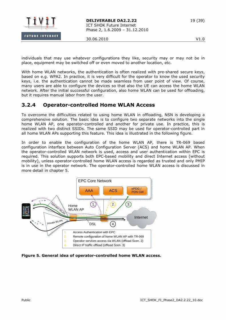
To overcome the difficulties related to using home WLAN in offloading, NSN is developing a
comprehensive solution. The basic idea is to configure two separate networks into the single
home WLAN AP, one operator-controlled and another for private use. In practice, this is
realized with two distinct SSIDs. The same SSID may be used for operator-controlled part in
all home WLAN APs supporting this feature. This idea is illustrated in the following figure.
In order to enable the configuration of the home WLAN AP, there is TR-069 based
configuration interface between Auto Configuration Server (ACS) and home WLAN AP. When
the operator-controlled WLAN network is used, access and user authentication within EPC is
required. This solution supports both EPC-based mobility and direct Internet access (without
mobility), unless operator-controlled home WLAN access is regarded as trusted and only PMIP
is in use in the operator network. The operator-controlled home WLAN access is discussed in
more detail in chapter 5.
EPC Core Network
AAAAAA
Home WLAN AP
Private WLAN
Operator WLAN
InternetRouterRouter
ePDG / PDN GWePDG / PDN GWACSACS
1. Access Authentication with EPC
2. Remote configuration of home WLAN AP with TR-0693. Operator services access via WLAN (offload Scen. 2)4. Direct IP traffic offload (offload Scen. 3)
1. 2. 3.
4.DSL
Figure 5. General idea of operator-controlled home WLAN access.

DELIVERABLE DA2.2.22 20 (39)
ICT SHOK Future Internet
Phase 2, 1.6.2009 – 31.12.2010
30.06.2010 V1.0
Public ICT_SHOK_FI_Phase2_DA2.2.22_10.doc
4 PBRM in WLAN Offload
In order to make WLAN offload beneficial for the operator, there is need for a mechanism that
the operator can use to influence what traffic UEs should offload and to what networks the
offload should take place. One of the reasons of PBRM development was to enable the operator
to influence on UE’s WLAN network selection decisions; thus, it is natural to extend PBRM
scope also for covering the WLAN offload.
As described in previous PBRM documents (e.g. [1]), the basic PBRM features include network
selection and discovery information provisioning. The network selection information is general
in that sense that it only identifies a single network for the UE at a given time; the idea is that
the UE should use that preferred access network for all the active applications. However, in
order to make most out of WLAN offload, it should be possible to use WLAN offload only for
selected applications while another set of applications could still use the cellular network. For
example, the operator most probably wants to keep the precious voice traffic in its own 3GPP
access network(s) where all the required QoS mechanisms are in place, whereas Internet-
based services like browsing could easily be offloaded to WLAN. In this chapter, it is considered
how PRBM concept should be extended to support policies per applications. Also, the
characteristics of different WLAN deployments (described in 3.2) are discussed from PBRM
point of view.
4.1 Application Information into PBRM Policies
To make PBRM framework to support application-based offloading three things are needed:
1. A mechanism to identify the applications,
2. A mechanism to indicate the preferred access network for this application,
and
3. A mechanism to indicate the intended offloading scenario.
For the last requirement, there are two options: either WLAN offload is used so that traffic is
routed via EPC or also EPC core network is bypassed (refer Figure 2 in 2.3).
4.1.1 Application Identification
The selected application identification mechanism needs to be future proof, i.e. the mechanism
has also to be able to cover the future applications in addition to the existing ones. Further,
the mechanism should be easy to apply both from the UE and operator point of view. In the
following, some possible mechanisms for application identification are discussed.
Application naming: In general, information about application is something that is delivered
from the PBRM server to the UE: in practice, it is enough that the UE can interpret the
information and map it to some real-life application. It would for example be possible to define
certain set of applications that are distinguishable – like Browser, Email, etc – and then agree

DELIVERABLE DA2.2.22 21 (39)
ICT SHOK Future Internet
Phase 2, 1.6.2009 – 31.12.2010
30.06.2010 V1.0
Public ICT_SHOK_FI_Phase2_DA2.2.22_10.doc
the naming conventions used within PBRM framework. However, this kind of mechanism is not
flexible and hardly future proof.
Application classification: It is possible to classify the applications based on the traffic the
application creates. For example, often used model in 3GPP is to classify the applications
following their QoS requirements: Background class could be used for time-insensitive
applications like Email or file downloading, Interactive for web browsing, Streaming for (non-
live) video and audio streaming and Conversational class for voice services and live streamings.
In this scheme, it is the responsibility of the UE to do the mapping of the current application to
one of the classes. With this approach, it is possible that the UEs from different vendors make
different mappings: the operator may not get the control it should with this scheme.
Another challenge is that nowadays many services may be launched within browser: for
example, YouTube, Facebook etc. may look the same for application classification, although
the service requirements are very different. Also, the service traffic may be run on top of
“wrong” protocol, e.g. HTTP is nowadays used a lot to carry video and audio streaming.
Application classification scheme does not cope very well with this kind of real-life network
usage.
Application filtering: The most flexible and versatile mechanism is to use so called IP 5-tuple
to classify application and its data. 5-tuple may include source and destination IP addresses,
source and destination ports and the used protocol. The good thing about this scheme is that it
can cope with any application, present or future: when classifying an application, at least one
of the 5-tuple values is different from other applications.
The bad thing is that it can be a nightmare for an operator to maintain. In practice, it also may
be difficult to map all the applications down to used port level, especially when an application
may use different ports every time it is launched. However, with the 5-tuples, it is also
possible to define only sub-set of the values and omit the unnecessary ones. It is also possible
to use ranges, e.g. to define destination port to have value ‘1000-2000’. For the source and
destination addresses, it is possible to use prefixes to identify certain subnet instead of a single
address.
Application identification with destination: 5-tuple can be used to identify the destination
address of the application. In practice, the destination address already identifies the
application accurately enough, especially for the offload purposes. For example, if the operator
wants to distinguish YouTube traffic, it is enough to define the IP prefix used for YouTube
servers, and omit all the other values of 5-tuple.
Another way to present application traffic destination is to use 3GPP Access Point Name (APN).
In practice, traffic of an application associated with a certain APN is routed via a specific
gateway in 3GPP core network (e.g. PDN GW). For example, normally IMS-based voice service
is bound to a specific APN: if the operator Elisa provided IMS services, the FQDN of the APN
used for IMS services could be e.g. ims.apn.epc.mnc05.mcc244.3gppnetwork.org. If PBRM
server indicated this APN is associated with certain access networks, the UE would be able to
deduce that it should select one of the indicated access networks for IMS-based voice services,
and route the application traffic towards the given APN, i.e. not bypass EPC.
Of course, if the target is just to distinguish the WLAN offloading scenarios 2 and 3 (from
Figure 2 in 2.3) from each other, APN is not necessary for that: a simple indication or flag
from PBRM – i.e. select either scenario 2 or 3 – is enough.

DELIVERABLE DA2.2.22 22 (39)
ICT SHOK Future Internet
Phase 2, 1.6.2009 – 31.12.2010
30.06.2010 V1.0
Public ICT_SHOK_FI_Phase2_DA2.2.22_10.doc
4.1.2 Recommended Method
To fulfill the requirements listed in the beginning of chapter 4.1, the following set of
information is recommended to be added to PBRM:
• Application identification: the operator identifies the application that should
be offloaded by defining only the corresponding destination/remote IP
address. In practice, it is possible to represent the remote address e.g. with
5-tuple, if it is preferred to have more flexibility for currently unseen future
use. Also, the mechanism should be flexible enough to represent more
generic rules: for example, offload all streaming traffic to WLAN. With 5-
tuple, this kind of information may be difficult to represent, especially if the
streaming traffic can be carried over various protocols, e.g. HTTP, RTP etc. If
better mechanism is not identified, defining only the remote address may
still be in practice the best method to distinguish also the most resource-
consuming application types, like streaming.
• Preferred access network(s) for the application: the operator defines
prioritized access network or a list of access networks that the applications
identified with the above mechanism should use. PBRM already supports a
general prioritized access network list; the same mechanism could be re-
used with a new mapping to the application(s) to offload. The application
identification and information about preferred access networks are needed to
realize WLAN offload scenario 2 (Figure 2 in 2.3).
• Offloading scenario indication: To distinguish the WLAN offloading scenario 3
from scenario 2, some indication is needed whether the UE should route the
traffic via EPC core network or directly to the Internet. In its simplest form,
this indication can be a flag included in PBMR WLAN offloading information.
From the remainder of this document, the information listed above is referred as WLAN offload
policy. In practice, WLAN offload policy can be combined together with the generic PBRM
network selection policies, or it is also possible that WLAN offload policy is represented as
separate set of information from other PBRM network selection policies.
4.2 PBRM WLAN Offload Usage
4.2.1 Use Cases
In this chapter, the usage of PBRM WLAN offload with different WLAN deployments is discussed.
It should be noted that in the case 3GPP operator only supports PMIP and the intended WLAN
offload network is regarded as trusted, only WLAN offload scenario 2 is possible. For
illustration, ANDSF syntax is used for the PBRM information examples given in Figure 6 and
Figure 7 below.
1. Only the generic PBRM network selection information is used: The simplest way
to realize some kind of WLAN offloading guidance for the UEs is to use only the
generic PBRM network selection information, i.e. the above described WLAN

DELIVERABLE DA2.2.22 23 (39)
ICT SHOK Future Internet
Phase 2, 1.6.2009 – 31.12.2010
30.06.2010 V1.0
Public ICT_SHOK_FI_Phase2_DA2.2.22_10.doc
offload policy additions for PRBM framework are NOT used. In this case, the
operator just defines the WLAN networks the UE should be using, but leaves it
up to the UE to decide what applications UE runs over the WLAN networks and
what not. From the operator point of view, this may bring some benefits in
terms of offloaded traffic, but it is also possible the end result is harmful: some
UEs may try to offload applications that do not work or work poorly over the
WLAN network and the user only sees bad service. While this use case is
possible with the (basic) PBRM, it is recommended that also the offload
additions for PBRM framework are taken into use.
An example of PBRM information for this use case is given in the figure below:
2. WLAN offload policy additions to PRBM are used: Here, the operator-defined
PBRM information includes also application identification, preferred access
network for those and offloading scenario indication (refer to 4.1.2).
• Hotspots: if the operator AAA mechanisms are used with the hotspot and
either PMIP or DSMIPv6 is supported, it will be possible to seamlessly
(without user interaction) offload traffic to hotspot. In that case, hotspots
are very useful in WLAN offloading, and both offloading scenarios 2 and 3
are possible, assuming hotspot is regarded as untrusted. If it is not possible
to use operator AAA mechanisms, the authentication may not happen
automatically and only WLAN offloading scenario 3 is possible. The same is
true if there is no support for either PMIP or DSMIPv6.
• Operator managed WLAN networks: These networks are connected to the
operator AAA mechanisms, and makes the offloading very attractive. Most
probably, these networks are considered trusted, so for the operators
supporting only PMIP, the solely supported WLAN offloading scenario is 2.
For the operators having support for DSMIPv6, also scenario 3 is possible.
• Enterprise WLAN networks: This is applicable only for the employees of the
enterprise. If the enterprise’s own AAA machinery is not integrated with the
Use case 1: ./ANDSF/Policy/Set_1/RulePriority = 1 ./ANDSF/Policy/Set_1/PrioritizedAccess/1/AccessTechnology = WLAN ./ANDSF/Policy/Set_1/PrioritizedAccess/1/AccessID = HomeRun ./ANDSF/Policy/Set_1/PrioritizedAccess/1/AccessNetworkPriority=10 ./ANDSF/Policy/Set_1/PrioritizedAccess/2/AccessTechnology = 3GPP ./ANDSF/Policy/Set_1/PrioritizedAccess/2/AccessNetworkPriority = 30 ./ANDSF/Policy/Set_2/RulePriority = 2 ./ANDSF/Policy/Set_2/PrioritizedAccess/1/AccessTechnology = WLAN ./ANDSF/Policy/Set_2/PrioritizedAccess/1/AccessID = Coffee_shop ./ANDSF/Policy/Set_2/PrioritizedAccess/1/AccessNetworkPriority=20 ./ANDSF/Policy/Set_2/PrioritizedAccess/2/AccessTechnology = 3GPP ./ANDSF/Policy/Set_2/PrioritizedAccess/2/AccessNetworkPriority = 30
Figure 6. An example of general PBRM network selection information without application-specific WLAN offload policy information.

DELIVERABLE DA2.2.22 24 (39)
ICT SHOK Future Internet
Phase 2, 1.6.2009 – 31.12.2010
30.06.2010 V1.0
Public ICT_SHOK_FI_Phase2_DA2.2.22_10.doc
operator’s (which is very probable), only the offloading scenario 3 will be
supported.
• Home WLAN networks: generic home WLAN networks are most probably not
connected to the operator’s AAA machinery. Unless the home network is
provided by the operator, there is currently no way how the operator could
know the characteristics (e.g. SSID) of the home WLAN network. This means
that the operator cannot advertise the specific home network with PBRM. It
is up to the user (manually) to control if WLAN network is used for some
applications or not. In some sense, this could be considered as a (manual)
support for WLAN offloading scenario 3, but definitively there is no chance
for the operator to influence on the usage of WLAN offload.
• Operator-controlled home WLAN access: a special solution for home WLAN.
As shortly described in 3.2.4 and in more detail in chapter 5, the special
operator WLAN network configured (via TR-069) into the home WLAN AP is
connected to operator AAA mechanisms. Also, the SSID (of the operator
part) is known to the operator, so it is possible to include this information
into PBRM too. If the operator-controlled WLAN is considered as trusted and
only PMIP is supported, only WLAN offload scenario 2 will be possible.
Otherwise, also offloading scenario 3 is possible.
An example of PBRM information for this use case is given in the figure below. Here it is
assumed that the WLAN offload policy information is combined or integrated with the generic
PBRM network selection policy information, i.e. WLAN offload policy information cannot be used
as standalone.
Use case 2:
./ANDSF/Policy/Set_?/ [The same as in Use case 1 above, Figure 6] ./ANDSF/OffloadPolicy/Set_1/Appl_ID/1/Dest_IP = 74.125.4.0/24 ./ANDSF/OffloadPolicy/Set_1/PrioritizedAccess/Ref = ./ANDSF/Policy/
Set_2 ./ANDSF/OffloadPolicy/Set_1/OffloadScen = 1 /* Scen 3 */ ./ANDSF/OffloadPolicy/Set_2/Appl_ID/1/Dest_IP = 194.252.88.100 ./ANDSF/OffloadPolicy/Set_2/PrioritizedAccess/Ref = ./ANDSF/Policy/
Set_1 ./ANDSF/OffloadPolicy/Set_2/OffloadScen = 0 /* Scen 2 */
Figure 7. An example of PBRM WLAN offload policy information with application and offloading scenario indications.

DELIVERABLE DA2.2.22 25 (39)
ICT SHOK Future Internet
Phase 2, 1.6.2009 – 31.12.2010
30.06.2010 V1.0
Public ICT_SHOK_FI_Phase2_DA2.2.22_10.doc
4.2.2 Possible Workflow for the Operator
In order to make WLAN offload an effective tool for the operator, it is not necessary to identify
every single possible application on the network and then define PBRM information for all of
those. Instead in practice, it is often enough to distinguish only e.g. couple of the most
resource consuming applications. This can be done e.g. by following the traffic going through
the operator network, and then modify the PBRM rules accordingly. When defining PBRM rules
only for a small subset of applications, the operation and management burden on the operator
can be minimized.
In the following, an example workflow for the operator is given:
1. The operator monitors the traffic in the network
2. If there is excessive amount of traffic in some part of the network, the operator
identifies couple of worst applications (or destinations/remote hosts) that
creates most traffic.
3. If enabling or changing WLAN offload could help to solve the situation, new
PBRM rules for WLAN offloading are defined. The new PBRM WLAN offload
policies include application identification (i.e. the destination/remote IP address),
the WLAN networks to which the traffic should be offloaded and the intended
offload scenario (WLAN offload scenario 2 or 3).
4. The new PBRM WLAN offload policies are put into the queue of the PBRM server
to be downloaded to the UEs when they next time contact the PBRM server. For
the UEs creating most traffic, it is also possible to push the new PBRM rules
immediately.
5. When the UE downloads the new PBRM WLAN offload policies, it will start to
follow them. When a new connection for an application is established, the UE
considers the updated PBRM WLAN offload policies and acts accordingly.
The above described workflow can be used to enable WLAN offload for selected UEs – or for all
the UEs – and also modify the UE behavior for WLAN offload by updating the PBRM rules. This
way, the operator may quickly react to a changing situation in the network traffic.
5 Routing and Mobility with Operator-controlled Home WLAN Access
In this chapter, we will take a closer look on the operator-controlled WLAN access. The main
emphasis of this chapter is on the routing and mobility support of different network elements
when a UE gets IP connectivity via operator-controlled home WLAN access.
It is assumed that the operator providing the operator-controlled home WLAN access is using
3GPP EPC as cellular core network. In practice, this means that e.g. SIM-based AAA
procedures and the general EPC mobility support between different access technologies based

DELIVERABLE DA2.2.22 26 (39)
ICT SHOK Future Internet
Phase 2, 1.6.2009 – 31.12.2010
30.06.2010 V1.0
Public ICT_SHOK_FI_Phase2_DA2.2.22_10.doc
on either PMIP or DSMIP can be used. Also, it is assumed that one operator-controlled home
WLAN access is connected to only one EPC core network, i.e. there is one-to-one relationship
between the home access and the operator.
Further, the discussion on this chapter considers only untrusted non-3GPP accesses, i.e. it is
assumed that the WLAN network used to provide operator-controlled home WLAN access is
regarded as untrusted from the operator point of view. In general, nothing prohibits the
operator to treat the home WLAN access also as trusted, but since the WLAN equipment is
physically installed outside the operator reach, it is probably safer for the operator to rely on
the procedures defined for untrusted non-3GPP accesses. Further, as discussed earlier in
chapters 3.1.1 and 3.1.2, it is not possible to use direct IP traffic offload (WLAN offloading
scenario 3) with trusted WLAN access networks when PMIP is used, since there is no local
address allocated for the UE. Thus, treating the operator-controlled home WLAN access as
untrusted gives the operator more options for offloading.
The structure of chapter 5 is the following: first on 5.1, the general architecture of the
operator-controlled home WLAN access is shortly described. Also, the way how it can be
connected with EPC and its services is discussed. Chapter 5.2 concentrates how IP addresses
are allocated in practice with EPC with or without the two possible IP mobility solutions. On
chapter 5.3, the requirements for routing on the UE, WLAN AP and in other network elements
are discussed. 5.4 discusses the mobility related to the operator-controlled home WLAN access,
and 5.5 summarizes this chapter.
5.1 General Architecture for Operator-controlled Home WLAN Access
The main idea of operator-controlled home WLAN access is to enable WLAN offload also for the
home WLAN networks. The solution allows the operator to manage the home WLAN network
without interfering the usage of the private home WLAN. The operator-controlled home WLAN
access supports both WLAN offloading scenarios 2 and 3.
5.1.1 General Architecture
As briefly described in 3.2.4, the operator-controlled home WLAN access relies on using two
distinct WLAN networks on the home WLAN equipment. For the end user, these two networks
are visible as two different SSIDs. The operator SSID defines within the same physical
equipment the second virtual WLAN access point that can have own traffic routing and security
solutions. As with any other SSID, the operator SSID may or may not be hidden, depending on
the operator preferences. In Figure 8, the general architecture of the operator-controlled
home WLAN access is shown.
The basic idea of the operator-controlled home WLAN access is to separate the functions of the
private and “public” operator networks. The usage of the private network is the same as with
any other private WLAN APs, user can configure and use it as he wishes. However, the
operator part is in the operator’s control completely. In practice, this control can be realized by
using TR-069 based configuration interface [12], as shown in the figure. With TR-069, it is
possible to alter the settings of the Customer Premises Equipment (CPE) remotely e.g. over

DELIVERABLE DA2.2.22 27 (39)
ICT SHOK Future Internet
Phase 2, 1.6.2009 – 31.12.2010
30.06.2010 V1.0
Public ICT_SHOK_FI_Phase2_DA2.2.22_10.doc
ADSL line. Auto Configuration Server (ACS) together with CPE manager and database form the
network side of the TR-69 system. TR-069 support is also required from the CPE, i.e. home
WLAN AP equipment. The internal functional entities of the home equipment are further
discussed on the next sub-chapter 5.1.2.
On the figure below, two ADSL network elements are visible: DSLAM and BRAS. Digital
Subscriber Line Access Multiplexer (DSLAM) is the unit containing the line termination of the
subscriber line and the aggregation function to split and combine user traffic from individual
lines towards a high capacity transport infrastructure in the access network. Broadband
Remote Access Server (BRAS) acts as access router and access control and policy gateway for
enabling user access to the Internet and services provided within the Network Service Provider
(NSP) network. User sessions are established in the BRAS usually by use of PPPoE (Point-to-
Point Protocol over Ethernet).
Operator WLAN TR-69 capable
DSL Router w/WLAN AP
Accessnetwork
DSLAM BRAS
NSPNetwork
Internet
ACS
Home NetworkCustomer WLAN
CPE Manager
DB
AAAProxy
HLR
3GAAA
ePDG
DSLAAA
PBRM/ANDSF
EPC
Figure 8. General architecture for operator controlled home WLAN access.
Depending on the deployment, NSP network may be operated by the same operator as EPC. In
that case, it is up to the operator to decide how to realize the connectivity between ADSL /
NSP network and EPC. If the ADSL and EPC operators are different, it is assumed that IP
packets can be routed between ADSL / NSP network and EPC. In practice, it means that the IP
address of ePDG is not private and can be reached from NSP and UE. ePDG is the gateway to
access EPC from non-3GPP access networks. More detailed discussion on EPC and its network
elements can be found e.g. from [8].
In order to secure the operator-controlled home WLAN access, the WPA Enterprise security
suite is used on WLAN AP. When accessing the operator WLAN part, EPC-based AAA
procedures are executed between the UE and EPC. For that, EAP-AKA is used. The WLAN AP is
required to be able to forward the EAP messages between the UE and EPC AAA server (or
to/from another AAA proxy, if the EPC AAA server is accessed via another proxy). During the
EAP-AKA process, also the WPA encryption keys to secure the WLAN air interface are
negotiated.

DELIVERABLE DA2.2.22 28 (39)
ICT SHOK Future Internet
Phase 2, 1.6.2009 – 31.12.2010
30.06.2010 V1.0
Public ICT_SHOK_FI_Phase2_DA2.2.22_10.doc
5.1.2 Functional Entities
When considering routing with the operator-controlled home WLAN access, it is good to take a
look at the required functional entities within WLAN AP itself. In Figure 9, the white entities
represent the functions of the private side, i.e. those entities can be found from any standard
WLAN AP equipment. The yellow entities belong to the operator side and are not configurable
by the user, only by the operator via TR-069 interface.
WLANInterface
DSLModem
ETHSwitch
PPPoEClient
RouterNAT IP Filter
AAA Proxy / RADIUS
Client
PPPoEClient
RouterNAT IP Filter
Private SSID
DHCP
DHCP
Operator SSID
Figure 9. Functional entities of operator-controlled home WLAN access within WLAN
AP equipment.
The separation of private and public sides on the figure is only logical; it does not reflect how
real products should be implemented. In practice, only WLAN interface and DSL modem are
physical entities that cannot easily be multiplied e.g. with software.
For IP address allocation in home WLAN AP, both private and operator sides have their own
DHCP servers. Since the two SSIDs – operator and private SSID – provide access to two
different networks, also the allocated IP addresses should be from different subnets. The
operator side DHCP only provides addresses for devices connecting via WLAN air interface.
AAA proxy on the figure is required for conveying EAP-AKA messages between the UE and EPC.
In practice, the connection between an AAA proxy and server need to be setup and configure
beforehand; TR-069 interface can be used for configuring AAA proxy on home WLAN AP, if
needed. In general, any WLAN AP supporting WPA Enterprise security suite should have AAA
proxy functionality built in.
As can be seen from the figure, also the data paths of the private and operator sides are
separated from each other. The intention is that the operator side can only be accessed after
successful authentication with EPC. Thus, home WLAN AP need to make sure that the security
of the operator side is not compromised, and it is e.g. not possible to access operator side via
private side. Also, all traffic from the operator SSID is always routed directly to ADSL (and vice
versa), whereas traffic on the private side may be routed either to private WLAN SSID,
Ethernet interfaces or ADSL line.

DELIVERABLE DA2.2.22 29 (39)
ICT SHOK Future Internet
Phase 2, 1.6.2009 – 31.12.2010
30.06.2010 V1.0
Public ICT_SHOK_FI_Phase2_DA2.2.22_10.doc
5.1.3 Role of PBRM
As was discussed in chapter 4.2, PBRM (or ANDSF in case of EPC) can very well be used with
the operator-controlled home WLAN access. In fact, PBRM is the only mechanism for the
operator to influence on the usage of operator-controlled home WLAN access, and thus it is an
important part of the concept.
Since the SSID used on the operator side on the home WLAN AP is known to the operator (the
operator configures the SSID), it is possible to include information about it in the PBRM
database. In practice, it is possible to provide either only the generic PBRM network selection
information (no application-specific info) or also the WLAN offload policy information (different
network selection rules for different applications). Since operator-controlled home WLAN
access is managed by the operator, it should be safe to assume that the operator services can
also be run on top of WLAN connection (i.e. no firewalls or NATs blocking traffic unexpectedly),
so also the generic PBRM network selection information can be used. However, more accurate
influence on the offloaded traffic type can be achieved when the WLAN offload policies are used.
It should also be noted that in practice PBRM can only be used to provide information for the
operator side (with operator SSID) of the home WLAN AP, i.e. the private side (with private
SSID) is completely unknown to the PBRM server. This means that the usage of the private
side is fully up to the user and the implementation of the UE.
5.2 IP Address Allocation
When getting the connectivity via the operator-controlled home WLAN access, the UE has two
options: either to access the operator SSID and acquire IP address(es) as specified for non-
3GPP access of EPC, or to access the private SSID as any other WLAN AP with local IP address
allocation.
When the UE decides to access the operator SSID – e.g. based on the network selection or
WLAN offload policies received from PBRM – the 3GPP-defined procedures for non-3GPP
accesses are followed (refer e.g. to [6] for details). Depending on the selected IP mobility
protocol, the procedures are slightly different. Both PMIP and DSMIPv6 scenarios are discussed
separately. After that, accessing the private SSID is also considered for comparison.
5.2.1 Accessing Operator SSID, PMIP Scenario
In general, depending on the WLAN network deployment, there may or may not be access
authentication performed before a UE is granted access to the WLAN network and an IP
address is allocated. With the operator-controlled home WLAN access, operator AAA
mechanisms are used also for access authentication. From WLAN access, this requires support
for WPA Enterprise security suite: this enables conveying the required EAP-AKA messages
between the UE and EPC core network. The following discussion applies for untrusted non-
3GPP accesses, i.e. WLAN networks.
When the WLAN access authentication based on EAP-AKA has successfully been completed, a
local IP address can be allocated to the UE. In practice, the operator side DHCP server on the
WLAN AP (refer to Figure 9) is responsible for that after getting access approval from AAA

DELIVERABLE DA2.2.22 30 (39)
ICT SHOK Future Internet
Phase 2, 1.6.2009 – 31.12.2010
30.06.2010 V1.0
Public ICT_SHOK_FI_Phase2_DA2.2.22_10.doc
functionality. Currently, most of home WLAN equipment allocates IPv4 addresses, but the local
IP address can also be IPv6 address. On Figure 10, IP address allocation for PMIP scenario is
shown. In principle, the UE could stop here with IP address allocation process, and only use
the local IP address for Internet services (WLAN offload scenario 3), without the access to EPC
services.
IPLocal from
WLAN access
IPSec
UE 3GPP IP connectivityIPHoA
UE Untrusted non-3GPP access
WLAN air if
ePDG
Lower layers
Lower layers
IP
Lower layers
IP
Lower layers
IP
Lower layers
IP
Internet
Router PDN GW
Application layer
S2b
IP
PMIP tunnel
* * Local IP connectivity
Figure 10. Schematic view of application and IP connectivity layers with PMIP on
untrusted non-3GPP access (S2b interface).
In order to continue the IP address allocation with EPC, an IPSec tunnel establishment is
initiated. Since the tunnel is established between the UE and ePDG, WLAN AP is not required to
have any tunneling mechanisms of its own. First, UE needs to find out the IP address of ePDG
by standard DNS mechanisms. When the ePDG IP address is available, the UE initiates IKEv2
tunnel establishment procedure towards the ePDG. As part of the IKEv2 tunnel establishment,
public key-based authentication with certificates is used to authenticate the ePDG. The UE is
authenticated based on credentials on the SIM: within IKEv2, EAP-AKA is run to perform
authentication and key agreement. After successfully completing the IKEv2 authentication and
tunnel establishment, ePDG includes the IP address in the final IKEv2 message sent to the UE.
This IP address is allocated in PDN GW during the authentication procedure and it is the home
address (HoA) of the UE. The HoA can be either IPv4 or IPv6 address, depending on the
operator deployment and UE support. In summary, the UE has two IP addresses: the local IP
address for communicating with ePDG (or for offloading traffic directly to the Internet) and the
home address for accessing services via EPC.
It should be noted that during the above steps, EAP-AKA procedure is run twice; first with
access authentication and then during IKEv2 tunnel establishment.
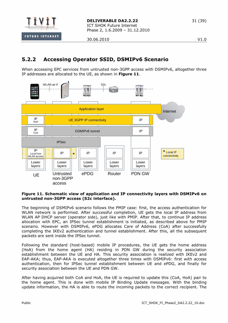
DELIVERABLE DA2.2.22 31 (39)
ICT SHOK Future Internet
Phase 2, 1.6.2009 – 31.12.2010
30.06.2010 V1.0
Public ICT_SHOK_FI_Phase2_DA2.2.22_10.doc
5.2.2 Accessing Operator SSID, DSMIPv6 Scenario
When accessing EPC services from untrusted non-3GPP access with DSMIPv6, altogether three
IP addresses are allocated to the UE, as shown in Figure 11.
IPLocal from
WLAN access
IPSec
UE 3GPP IP connectivityIPHoA
UE Untrusted non-3GPP access
WLAN air if
ePDG
Lower layers
Lower layers
IP
Lower layers
IP
Lower layers
IP
Lower layers
IP
Internet
Router PDN GW
Application layer
S2c
IP
DSMIPv6 tunnelIPCoA
IP
* * Local IP connectivity
Figure 11. Schematic view of application and IP connectivity layers with DSMIPv6 on
untrusted non-3GPP access (S2c interface).
The beginning of DSMIPv6 scenario follows the PMIP case: first, the access authentication for
WLAN network is performed. After successful completion, UE gets the local IP address from
WLAN AP DHCP server (operator side), just like with PMIP. After that, to continue IP address
allocation with EPC, an IPSec tunnel establishment is initiated, as described above for PMIP
scenario. However with DSMIPv6, ePDG allocates Care of Address (CoA) after successfully
completing the IKEv2 authentication and tunnel establishment. After this, all the subsequent
packets are sent inside the IPSec tunnel.
Following the standard (host-based) mobile IP procedures, the UE gets the home address
(HoA) from the home agent (HA) residing in PDN GW during the security association
establishment between the UE and HA. This security association is realized with IKEv2 and
EAP-AKA; thus, EAP-AKA is executed altogether three times with DSMIPv6: first with access
authentication, then for IPSec tunnel establishment between UE and ePDG, and finally for
security association between the UE and PDN GW.
After having acquired both CoA and HoA, the UE is required to update this (CoA, HoA) pair to
the home agent. This is done with mobile IP Binding Update messages. With the binding
update information, the HA is able to route the incoming packets to the correct recipient. The

DELIVERABLE DA2.2.22 32 (39)
ICT SHOK Future Internet
Phase 2, 1.6.2009 – 31.12.2010
30.06.2010 V1.0
Public ICT_SHOK_FI_Phase2_DA2.2.22_10.doc
HoA can be either IPv4 or IPv6 address, depending on the operator deployment and UE
support.
Now the UE has three IP addresses: the local IP address for communicating with ePDG (or for
offloading traffic directly to the Internet), the Care of Address that is used for DSMIPv6
tunneling and the home address for accessing services via EPC.
5.2.3 Accessing Private SSID
Accessing the private SSID of the operator-controlled home WLAN access does not differ from
accessing any generic home WLAN. It is up to the WLAN AP implementation to ensure that the
private and operator SSIDs are disconnected from each other for configuration, IP address
allocation and traffic routing. Any available WLAN authentication mechanism can be used with
the private SSID. For example, if WPA2 pre-shared key mode (i.e. the personal mode) is used,
WLAN AP may deploy push button mechanism for easy setup of the encryption and the
required encryption keys (i.e. pre-shared key, PSK). After the UE is authenticated for the local
WLAN AP, DHCP server of the private side (refer to Figure 9) allocates the local IP address for
the UE. It should be noted that the UE can only be connected to a single SSID at a time, i.e.
the UE gets its local IP address allocated either by the operator or private side of the WLAN AP.
5.2.4 Sending Packets
On Figure 12, examples of sent uplink IP packets with different header structure are shown.
In both PMIP and DSMIPv6 scenarios, Encapsulated Security Payload (ESP) protocol of IPSec is
used in so called tunneled mode, where the complete IP packet is protected, not just payload.
ESP header is added in front of the protected IP packet and its header (called inner IP header
in ESP terminology), and ESP trailer at the end of the protected IP packet. Since in practice
most of the home WLAN APs allocate IPv4 addresses only, there is NAT functionality within
WLAN AP. For the PMIP and DSMIPv6 scenarios, it is up to IPSec and ESP to take care of NAT
traversal, e.g. by using UDP encapsulation (not shown in the figure below). Note: it is not in
the scope of this document to discuss the issues related to the used IP protocols in non-3GPP
interworking of EPC; this field may require further work, at least to verify there are no found
unsolved issues.
In the figure, the topmost packet structure represents an uplink IP packet sent with PMIP
towards EPC. The source address of the outer IP header is the (NATted) local IP address from
WLAN AP and the destination address is the IPv4 address of ePDG. In the actual payload
packet, the source address (inner IP header) is the HoA allocated from home agent in PDN GW
and the destination address is the address of remote host. When the packet reaches ePDG, it
will remove the outer IP header – i.e. it terminates the IPSec tunnel – and forwards the packet
further to home agent in the PDN GW that routes the inner packet towards the final recipient.
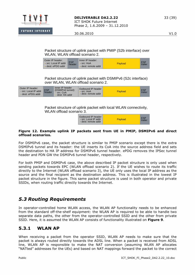
DELIVERABLE DA2.2.22 33 (39)
ICT SHOK Future Internet
Phase 2, 1.6.2009 – 31.12.2010
30.06.2010 V1.0
Public ICT_SHOK_FI_Phase2_DA2.2.22_10.doc
PayloadInner IP header:-- src: HoA-- dest: remote addr
ESP header
ESP trailer
Outer IP header:-- src: Local IP addr-- dest: ePDG addr
Packet structure of uplink packet with PMIP (S2b interface) overWLAN, WLAN offload scenario 2.
Payload
Inner IP header (DSMIPv6 tunnel):-- src: CoA-- dest: HA addr
ESP header
ESP trailer
Outer IP header:-- src: Local IP addr-- dest: ePDG addr
Outbound IP header-- src: HoA-- dest: remote addr
Packet structure of uplink packet with DSMIPv6 (S2c interface) over WLAN, WLAN offload scenario 2.
Payload ESP trailer
Outbound IP header-- src: Local IP addr-- dest: remote addr
Packet structure of uplink packet with local WLAN connectivity, WLAN offload scenario 3.
Figure 12. Example uplink IP packets sent from UE in PMIP, DSMIPv6 and direct
offload scenarios.
For DSMIPv6 case, the packet structure is similar to PMIP scenario except there is the extra
DSMIPv6 tunnel and its header: the UE inserts its CoA into the source address field and sets
the destination to HA IP address for DSMIPv6 tunnel header. ePDG removes the IPSec tunnel
header and PDN GW the DSMIPv6 tunnel header, respectively.
For both PMIP and DSMIPv6 case, the above described IP packet structure is only used when
sending packets towards EPC (WLAN offload scenario 2). If the UE wishes to route its traffic
directly to the Internet (WLAN offload scenario 3), the UE only uses the local IP address as the
source and the final recipient as the destination address. This is illustrated in the lowest IP
packet structure in the figure. This same packet structure is used in both operator and private
SSIDs, when routing traffic directly towards the Internet.
5.3 Routing Requirements
In operator-controlled home WLAN access, the WLAN AP functionality needs to be enhanced
from the standard off-the-shelf equipment: the WLAN AP is required to be able to handle two
separate data paths, the other from the operator-controlled SSID and the other from private
SSID. Here, it is assumed the WLAN AP consists of functionality illustrated on Figure 9.
5.3.1 WLAN AP
When receiving a packet from the operator SSID, WLAN AP needs to make sure that the
packet is always routed directly towards the ADSL line. When a packet is received from ADSL
line, WLAN AP is responsible to make the NAT conversion (assuming WLAN AP allocates
“NATted” addresses for the UEs) and based on NAT mappings forward the packet to the correct

DELIVERABLE DA2.2.22 34 (39)
ICT SHOK Future Internet
Phase 2, 1.6.2009 – 31.12.2010
30.06.2010 V1.0
Public ICT_SHOK_FI_Phase2_DA2.2.22_10.doc
recipient either via the operator or private data path. If the packet is destined to the operator
data path, the only destination the received packet can take is the operator SSID. However, if
the packet is destined to the private data path, WLAN AP may route the packet either towards
the private WLAN SSID or Ethernet interfaces (if available). Correspondingly, a packet received
from the private SSID can be routed either back to the private WLAN SSID (if also the
recipient resides in the private WLAN SSID), Ethernet interfaces or towards ADSL line. The
above described is the basic routing functionality that is required from the WLAN AP in
operator-controlled home WLAN access.
When WLAN AP forwards packets towards ADSL line, it is assumed that the next hop router
behind the WLAN AP router functionality – e.g. BRAS (refer to Figure 8), or another router
behind it – is able to forward the data packets towards the recipient. The recipient may be
reachable e.g. via ePDG gateway or gateway that provides access directly to the Internet.
Since in the operator-controlled home WLAN access the WLAN air interface is divided between
two different SSIDs, also the capacity may be limited if both SSIDs are used at the same time.
Standard WLAN mechanisms can be used to prioritize traffic on radio interface, but it may also
be necessary to limit the amount of overall traffic sent through either the operator or private
data paths. The router functionality could be extended to implement this kind of limiter, e.g.
by buffering some data for a short period of time if the level of consumed resources gets too
high.
5.3.2 UE
In operator-controlled home WLAN access, also the UE is required to participate in routing.
Since both the IPSec and DSMIPv6 tunnels terminate on the UE, only the UE can decide to
what tunnel an IP packet should be directed. On the UE, a routing engine is responsible for the
routing decisions, as illustrated on Figure 13. It is possible that the destination to which traffic
should be sent can be reachable via multiple routes: 3G or LTE connection via EPC may be one
option or then non-3GPP radio access with or without EPC connectivity may be used.
In order to help the UE in routing and to provide the operator means to influence on the access
selection, PBRM WLAN offload policies can be used to guide UE’s routing engine in its routing
decisions. As discussed in chapter 4, the PBRM WLAN offload policies are preferably
application-specific. Also, the PBRM WLAN offload policies need to distinguish whether the
traffic is sent via EPC, or directly to the Internet. Together with PBRM policies and user
preferences, the UE can select the correct route for a new connection.
Depending on the implementation of the UE, the different routes to various destinations can be
represented in many ways: for example, DSMIPv6 tunnel may be shown as extra interface for
the applications. When sending data, it is the responsibility of the UE to route each packet on
the appropriate path based on the final destination, PBRM WLAN offload policies and other local
factors influencing routing engine decisions.

DELIVERABLE DA2.2.22 35 (39)
ICT SHOK Future Internet
Phase 2, 1.6.2009 – 31.12.2010
30.06.2010 V1.0
Public ICT_SHOK_FI_Phase2_DA2.2.22_10.doc
3G /LTE
IP
Upper layers
App App
RoutingEngine
WLAN
IPsec
WLAN offload Policies from
PBRM
App
Figure 13. Routing different application traffic on the UE.
5.3.2.1 Multiple Interface Handling
Multiple interfaces and their handling in the UE is a generic problem area that also affects how
well the operator-controlled home WLAN access works in practice. In short what is it all about:
hosts (or UEs) with multiple interfaces may receive configuration information from each access
network separately. Some of this configuration information is global for the host whereas some
is local and only valid to a single interface. Various issues may arise when conflicting
configuration information is received from multiple interfaces. For example, the correct DNS
server address may be different when using 3GPP or WLAN access, but some host
implementations may store the required DNS resolution information globally and overwrite any
previous, existing information.
IETF Multiple Interfaces (MIF) working group concentrates on this field of issues. MIF Problem
Statement [13] lists five areas of problems: configuration, DNS resolution, routing, address
selection and connection management. With the operator-controlled home WLAN access, PBRM
information can be utilized to solve the routing problem (at least partly), but the rest of the
problems remain for the UE to take care of. MIF working group aims to have standardized
practices for the above problems, but so far the work has mainly concentrated on identifying
the issues. In practice, it is up to the (proprietary) UE implementation to take care of handling
of multiple interface issues.
5.4 Mobility
With operator-controlled home WLAN access, it is possible to get the connectivity via either the
private or operator SSID. When the UE connects through the operator SSID, EPC-based
authentication and IP address allocation mechanisms are used. If the UE completes the IP
address allocation either with PMIP or DSMIPv6 protocol – as described above in 5.2 – and
uses the home address (HoA) to access services (i.e. the traffic is routed via EPC, WLAN
DELIVERABLE DA2.2.22 36 (39)
ICT SHOK Future Internet
Phase 2, 1.6.2009 – 31.12.2010
30.06.2010 V1.0
Public ICT_SHOK_FI_Phase2_DA2.2.22_10.doc
offload scenario 2), the mobility support is provided by the EPC based on standardized mobile
IP mechanisms. Of course, also the UE is required to have support for the IP mobility, as
discussed in chapter 3.1.2. For example, when the UE has received the HoA via the operator-
controlled home WLAN access and routes traffic via EPC, the UE may initiate the handover
towards e.g. 3GPP radio access or another WLAN when the connection quality to the operator
SSID degrades too much. After setting up the new radio access, UE updates the new IP
address to the HA by sending Binding Update message when DSMIPv6 is used; in the case of
PMIP the HoA of UE does not change, i.e. the network takes care of IP address modifications.
In principle, mobile IP based mobility can support any kind of traffic; it is up to the
implementations if the handover procedure is fast enough also for real-time traffic.
With the operator SSID, it is also possible to only use the local IP address to send data from
the UE. In this WLAN offload scenario 3, the traffic is routed directly to the Internet, i.e. EPC is
not used. That also means that mobile IP mechanisms EPC provides are not utilized. Thus,
there is no mobility support from the network for traffic routed directly to the Internet. If the
UE moves out of operator SSID coverage, the connection is lost and new setup of IP
connectivity is required. In practice, this results in allocation of a new, different IP address.
Normally in this case, some actions are required from the user to trigger the establishment of
a new connection.
When the UE accesses the private SSID of the operator-controlled home WLAN access, the
situation is similar to the above described scenario where only local IP address and WLAN
offload scenario 3 is utilized: there is no mobility support from the network.
Even if there is no mobility support from the network (e.g. in WLAN offload scenario 3), UEs
may implement local mobility mechanisms that work regardless of the network support. For
example, some Nokia devices have Application Level Roaming (ALR) that enables the
application continue working seamlessly even when the used IP address changes. Thus,
depending on the UE implementation, mobility may be possible in all WLAN offload scenarios
also with the operator-controlled home WLAN access.
5.5 Summary
With the operator-controlled home WLAN access, routing requires some functional
enhancements on the WLAN AP compared to standard WLAN equipment. The requirements on
the two distinct data paths – the operator and private sides – are a bit different: for the
operator side, all traffic is directly routed to/from the operator SSID from/to ADSL line whereas
on the private side, traffic can be routed between private SSID, Ethernet and ADSL line. In
general, to implement the added routing functionality for the operator side is not too complex
and should be feasible.
Also UE has an important role in operator-controlled home WLAN access concept. It is the
responsibility of the UE to make sure that each outgoing packet is routed via the correct access
using appropriate tunnels (i.e. IPSec, DSMIPv6), when needed. The UE routing decisions affect
also the mobility: if traffic is not routed via EPC, no mobility support is provided form the
network. In case traffic is routed via EPC, also the standard mobile IP based mobility support is
available.

DELIVERABLE DA2.2.22 37 (39)
ICT SHOK Future Internet
Phase 2, 1.6.2009 – 31.12.2010
30.06.2010 V1.0
Public ICT_SHOK_FI_Phase2_DA2.2.22_10.doc
Since the UE is in practice in charge of routing decisions for the operator-controlled home
WLAN access, the operator has to have means to influence on the routing decisions: PBRM
policies can be used for that.
6 Alternative Solution for Influencing UE’s Offload Decisions
Realizing WLAN offload with PBRM is not the only solution. For example, it is possible to rely on
existing mechanisms but to apply them in a modified way. One such a possibility is to use
Router Advertisement (RA) messages sent by IPv6 routers. RFC 4191 [11] adds some more
parameters to the standard Router Advertisement messages: for example, Default Router
Preference is added into the RA message header. The field has three values (low, medium,
high) and can be used in the host (i.e. UE) to prioritize default routes received from different
routers.
The idea behind using the RAs for influencing UE’s offload decisions is that the routers from
different access networks would send different priority values for their default routes. For
example, if the router from WLAN network sends RA with Default Router Preference ‘high’ and
RA received via LTE indicated “low” preference, the UE could interpret this information so that
WLAN access is preferable over LTE.
Good thing about this scheme is that it uses already existing mechanisms. Also, sending RA is
a lightweight procedure (e.g. compared to setting up an OMA DM connection for ANDSF
session, refer to [5]), and it can be used to quickly convey information about the network
selection preferences, if e.g. the information is changed. Periodic RAs are sent to multicast
address, so all the UEs within that network will receive the same RA and associated priorities.
When the router is answering for Router Solicitation sent from an UE, router may also use
unicast address, i.e. it is possible to direct the RA only to a single UE.
With only three values for preference, the mechanism based on RAs is somewhat limited
compared e.g. to PBRM. Also, there is no way to indicate what traffic should be offloaded in RA
messages. Since the used routing preference values have to be agreed above router level – i.e.
an operator sets the preference values – the mechanism works well only when the routers
sending preference values are from the same operator. For example, this mechanism could
only be used with operator managed WLAN network deployment scenario (refer to 3.2), unless
the preference values are agreed among operators.
7 Conclusions
Offloading traffic to WLAN networks is receiving more and more interest from operators. It can
be seen as an inexpensive but efficient mechanism to expand the capacity of cellular operator
networks. When WLAN offload is used, both signaling and user data traffic can be reduced in
cellular networks: it is possible to move to WLAN both the applications sending lots of status
updates and applications creating a lot of user data. Thus, WLAN offload can be considered
contributing for solving both the signaling traffic and user data increase problems.

DELIVERABLE DA2.2.22 38 (39)
ICT SHOK Future Internet
Phase 2, 1.6.2009 – 31.12.2010
30.06.2010 V1.0
Public ICT_SHOK_FI_Phase2_DA2.2.22_10.doc
In order to make WLAN offload useful for the operators, a mechanism to influence on the UE’s
offload decisions is needed. PBRM concept is a good tool for that. Also, PBRM provides effective
means for the operators to react on changing traffic conditions in the network. Together with
the operator-controlled home WLAN access, PBRM concept can be effectively used to enable
WLAN offloading also with home networks.
With the operator-controlled home WLAN access, routing requires some functional
enhancements on the WLAN AP to support the two distinct data paths. In general, these
enhancements are feasible to implement into home WLAN equipment.
For WLAN offload – as well as for the operator-controlled home WLAN access – the role of the
UE is important: it is the responsibility of the UE to make sure that each outgoing packet is
routed via the correct access using appropriate tunnels (i.e. IPSec, DSMIPv6), when needed.
The UE routing decisions affect also the mobility: if traffic is not routed via EPC, no mobility
support is provided form the network.
In general, WLAN offloading together with PBRM can be a valuable tool for the operators in
tackling the traffic growth in cellular networks.
8 References
[1] Policy-Based Resource Management, Future Internet Program deliverable 2.4.1,
version 1.0, 19.12.2008.
[2] Network Selection Simulations, Future Internet Program deliverable 2.4.3, version
1.0, 31.5.2009.
[3] Automated PBRM Server Configuration, Future Internet Program deliverable 2.4.2,
version 1.0, 26.6.2009.
[4] Service Based Access Selection with PBRM, Future Internet Program deliverable
2.2.21, version 1.0, 4.6.2009.
[5] Realization of Policy-Based Resource Management Concept, Future Internet
Program deliverable 2.2.20, version 1.0, 16.02.2009.
[6] 3GPP TS 23.402, Architecture enhancements for non-3GPP accesses, Release 9,
v9.3.0, December 2009.
[7] 3GPP TS 24.302, Access to the 3GPP Evolved Packet Core (EPC) via non-3GPP
access networks, v9.1.1, December 2009.
[8] SAE and the Evolved Packet Core, Driving the Mobile Broadband Revolution,
Magnus Olsson, Shabnam Sultana, Stefan Rommer, Lards Frid, Catherine Mulligan,
Academic Press, 2009
[9] 3GPP TS 29.273, 3GPP EPS AAA interfaces, V9.1.0, December 2009.

DELIVERABLE DA2.2.22 39 (39)
ICT SHOK Future Internet
Phase 2, 1.6.2009 – 31.12.2010
30.06.2010 V1.0
Public ICT_SHOK_FI_Phase2_DA2.2.22_10.doc
[10] 3GPP TS 23.261, IP Flow Mobility and seamless WLAN offload, v1.0.0, March 2010.
[11] RFC 4191, Default Router Preferences and More-Specific Routes, R. Draves, D.
Thaler, November 2005.
[12] TR-069 Amendment 2, CPE WAN Management Protocol v1.1, Broadband Forum,
viewable at http://www.broadband-forum.org/technical/download/TR-
069Amendment2.pdf
[13] IETF Draft Multiple Interfaces Problem Statement, draft-ietf-mif-problem-
statement-04.txt, M. Blanchet, P. Seite, May 17, 2010.