dell dvs enterprise: reference architecture for dell ... · 4.6 hyper-v configuration ... this...
TRANSCRIPT

Dell DVS Enterprise:
Reference Architecture for
Dell vWorkspace 8.0
Table of Contents
1 Introduction ................................................................................. 1 1.1 Purpose of this document .................................................................... 1 1.2 Scope ............................................................................................ 1
2 vWorkspace Solution Architecture Overview ......................................... 2 2.1 vWorkspace Solution Overview ............................................................. 2 2.2 vWorkspace Physical Architecture Overview .............................................. 2 2.3 Layouts and Breakpoints ...................................................................... 3
2.3.1 Local Tier 1 – Solution Layers .......................................................... 3 2.3.2 Dell DVS 10-Seat Trial Kit ............................................................... 4 2.3.3 Local Tier 1 – 50 User/ Pilot ............................................................ 4 2.3.4 Local Tier 1 – Combined ............................................................... 5 2.3.5 Local Tier 1 – Distributed ............................................................... 5 2.3.6 Local Tier 1 – Scale Out ................................................................ 6 2.3.7 High Availability .......................................................................... 7 2.3.8 Local Tier 1 – Converged Infrastructure ............................................. 7 2.3.9 Solution Density Summary ............................................................. 8
2.4 Cabling Diagrams .............................................................................. 8 2.4.1 Local Tier 1 – Network Architecture .................................................. 8 2.4.2 Local Tier 1 Cabling (<500 users) ...................................................... 9
3 Hardware Components .................................................................. 10 3.1 Network ........................................................................................ 10
3.1.1 Force10 S55 (ToR Switch) .............................................................. 10 3.1.1.1 Force10 S55 Stacking ............................................................. 10
3.2 Servers .......................................................................................... 11 3.2.1 Local Tier 1 Rack ........................................................................ 11
3.3 Storage ......................................................................................... 12 3.3.1 Equallogic Storage ...................................................................... 12
3.3.1.1 PS4100E ............................................................................ 12 3.3.1.2 PS6100E ............................................................................ 13 3.3.1.3 PS6500E ............................................................................ 14 3.3.1.4 NAS .................................................................................. 14 3.3.1.5 FS7600 .............................................................................. 14
3.4 Dell Wyse End Points ......................................................................... 15 3.4.1 Display Choices for Dell Wyse Endpoints ........................................... 15 3.4.2 Dell Wyse T10 ........................................................................... 15 3.4.3 Dell Wyse D10D ......................................................................... 16 3.4.4 Dell Wyse D10D ......................................................................... 16 3.4.5 Dell Wyse D90D8 ....................................................................... 17 3.4.6 Dell Wyse Z90D8 ....................................................................... 18
4 Solution Architecture for Dell vWorkspace ......................................... 19 4.1 Overview ....................................................................................... 19
4.1.1 vWorkspace Computer Group Options .............................................. 19 4.2 Compute Server Infrastructure ............................................................. 20 4.3 Management Server Infrastructure ......................................................... 21 4.4 Storage Architecture ......................................................................... 22
4.4.1 Local Tier 1 ............................................................................... 22 4.4.2 vWorkspace Hyper-V Catalyst Components (HCC) ............................... 23 4.4.3 Shared Tier 2 ............................................................................ 23 4.4.4 Virtual Hard Disk Format............................................................... 24 4.4.5 DNS ....................................................................................... 24

4.4.6 SQL Server ............................................................................... 24 4.4.7 File Services .............................................................................. 24 4.4.8 vWorkspace User Profile Management .............................................. 24
4.5 Foglight for Virtual Desktops ................................................................ 25 4.6 Hyper-V Configuration ...................................................................... 26
4.6.1 Core Components ...................................................................... 27 4.6.2 Hyper-V Networking (Local Tier 1) ................................................... 27
4.7 Solution High Availability .................................................................... 29 4.7.1 SQL Database HA ....................................................................... 30
4.8 Disaster Recovery and Business Continuity ............................................... 31 4.9 vWorkspace Data Flow ....................................................................... 32 4.10 Conclusion ................................................................................... 32
Appendix A – Dell DVS 10-Seat Trial Kit ................................................ 33 Server Configuration .............................................................................. 33 Management and Compute Infrastructure .................................................... 34 Storage Configuration ............................................................................ 35
Appendix B – Converged Infrastructure ............................................... 36
Appendix C – vWorkspace Desktop Cloud Performance Analysis Results (non-persistent VMs) .............................................................................. 38
Configuration Summary – Workload Independent Settings ................................ 39 Test 1: 230 Task Worker Users (Light) .......................................................... 40 Test 2: 170 Knowledge Worker Users (Medium) .............................................. 43 Test 3: 500 Knowledge Worker Users (Medium) ............................................. 46 Test 4: 230 Windows Server 2012 RD Sessions (Light) ...................................... 54 Test 5: 10-Seat Trial Kit ........................................................................... 56 Results Summary .................................................................................. 59 Conclusion ......................................................................................... 59
Appendix D – Foglight for Virtual Desktops Monitoring .............................. 60
About the Authors .......................................................................... 64

Dell DVS Reference Architecture for Dell vWorkspace 8.0
Page 1
1 Introduction
1.1 Purpose of this document
This document describes the Dell DVS Enterprise Reference Architecture for Dell vWorkspace.
This document addresses the architecture design, configuration and implementation considerations for the key components of the architecture required to deliver virtual desktops, RD Session Host sessions or applications via Dell vWorkspace on Hyper-V 2012.
1.2 Scope
Relative to delivering the virtual desktop environment, the objectives of this document are to:
● Define the detailed technical design for the solution.
● Define the hardware requirements to support the design.
● Define the design constraints which are relevant to the design.
● Define relevant risks, issues, assumptions and concessions – referencing existing ones where possible.
● Provide a breakdown of the design into key elements such that the reader receives an incremental or modular explanation of the design.
● Provide solution scaling and component selection guidance.

Dell DVS Reference Architecture for Dell vWorkspace 8.0
Page 2
2 vWorkspace Solution Architecture Overview
2.1 vWorkspace Solution Overview
The Dell vWorkspace Solution provides access to virtual desktops or applications via VDI, Physical PCs, and Virtual or Physical RD Session Hosts. vWorkspace also provides access to virtualized applications by way of Microsoft App-V and Linux Application Workloads by way of Linux Hosted Virtual Desktops or Physical Linux PCs.
While vWorkspace supports a variety of hypervisors, this DVS Enterprise Solution architecture is based on Microsoft Hyper-V.
2.2 vWorkspace Physical Architecture Overview
The core architecture design consists of the Local Tier1 solution model. “Tier 1” in the DVS context defines from which disk source the VDI sessions execute and in this case means local disks. Local Tier 1 applies to rack servers only while Shared Tier 1 can be rack or blade. Tier 2 shared storage is utilized for user profile/data and Management VM execution.
User DataMgmt Disk
MGMT Server
CPU RAM
T2 Shared Storage
Mgmt VMs
VDI VMs
Compute Server
CPU RAMVDI Disk
Local Tier 1
Dell DVS Reference Architecture for Dell vWorkspace 8.0
Page 3
2.3 Layouts and Breakpoints
The solution architecture will follow the traditional DVS distributed design model consisting of 4 primary layers: Network, Compute, Management, and Storage. The Network and Storage layers can be optionally provided by the customer if suitable infrastructure is already in place. The Compute layer contains the hosts that serve the VDI sessions and the Management layer contains the components required to support the Dell vWorkspace infrastructure.
The following highlights the key layout and scaling elements of the solution.
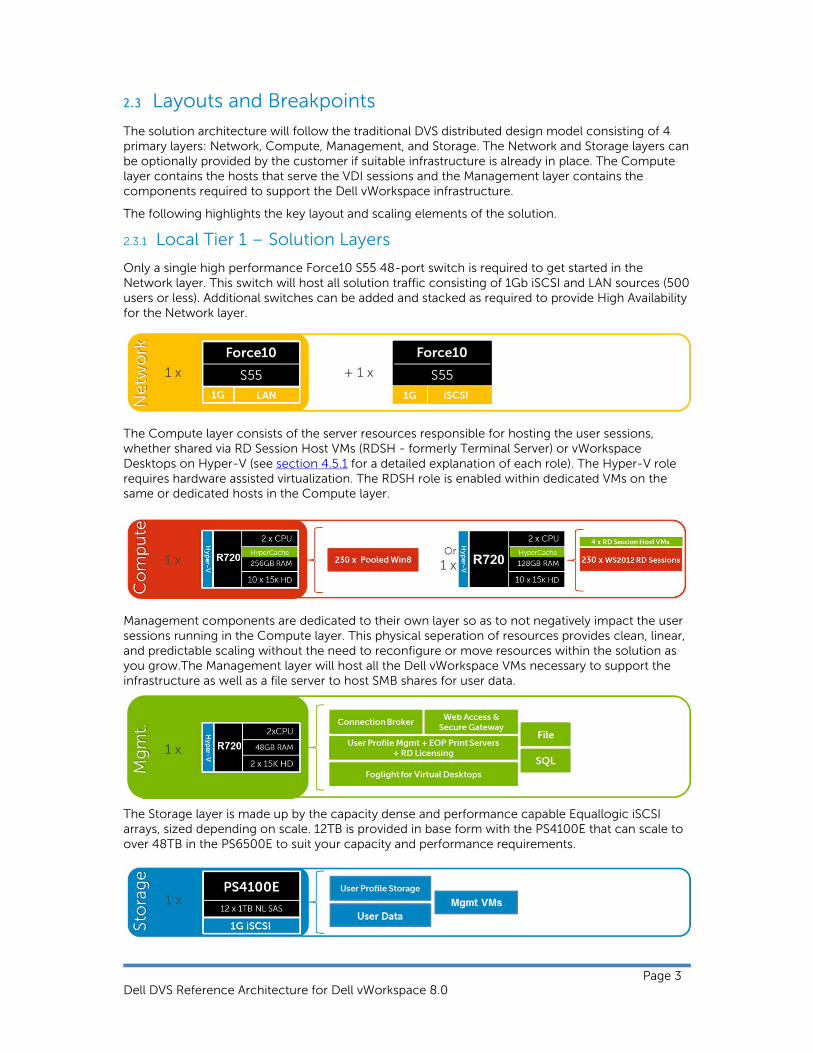
2.3.1 Local Tier 1 – Solution Layers
Only a single high performance Force10 S55 48-port switch is required to get started in the Network layer. This switch will host all solution traffic consisting of 1Gb iSCSI and LAN sources (500 users or less). Additional switches can be added and stacked as required to provide High Availability for the Network layer.
The Compute layer consists of the server resources responsible for hosting the user sessions, whether shared via RD Session Host VMs (RDSH - formerly Terminal Server) or vWorkspace Desktops on Hyper-V (see section 4.5.1 for a detailed explanation of each role). The Hyper-V role requires hardware assisted virtualization. The RDSH role is enabled within dedicated VMs on the same or dedicated hosts in the Compute layer.
Management components are dedicated to their own layer so as to not negatively impact the user sessions running in the Compute layer. This physical seperation of resources provides clean, linear, and predictable scaling without the need to reconfigure or move resources within the solution as you grow.The Management layer will host all the Dell vWorkspace VMs necessary to support the infrastructure as well as a file server to host SMB shares for user data.
The Storage layer is made up by the capacity dense and performance capable Equallogic iSCSI arrays, sized depending on scale. 12TB is provided in base form with the PS4100E that can scale to over 48TB in the PS6500E to suit your capacity and performance requirements.

Dell DVS Reference Architecture for Dell vWorkspace 8.0
Page 4
2.3.2 Dell DVS 10-Seat Trial Kit
To get up and running as quickly as possible with pooled VDI, Dell is offering an extremely affordable solution capable of supporting 10 concurrent users for a minimal investment. This architecture leverages an inexpensive single server platform intended to demonstrate the capabilities of VDI for a small environment or focused POC/ trial. Networking is provided optionally in this solution and all VDI roles/ sessions are hosted on a single server.
For more information on the 10-Seat Trial Kit, please see Appendix A.
2.3.3 Local Tier 1 – 50 User/ Pilot
For a very small deployment or pilot effort to familiarize yourself with the DVS Enterprise solution architecture, we offer a 50 user/ pilot solution completely scalable to the maximum supported configuration. The architecture for the 50 user pilot follows a non-distributed model with all VDI and Management functions running on a single host. If additional scaling is desired, you can grow into a larger distributed architecture seamlessly with no loss on initial investment.

Dell DVS Reference Architecture for Dell vWorkspace 8.0
Page 5
2.3.4 Local Tier 1 – Combined
As a logical entry point to the distributed Dell vWorkspace solution stack, a combined architecture is offered to host both the vWorkspace Desktops and RDSH role within the same physical Compute host while separating the Management layer. This will enable users requiring either shared RDSH or pooled VDI sessions to be hosted on the same physical server. The value of this solution is a minimal infrastructure investment with maximum VDI flexibility easily tailored to shared and pooled user types. Horizontal scaling is achieved simply by adding additional Compute hosts. Additional information on the hardware components can be found in section 3 below.
2.3.5 Local Tier 1 – Distributed
In the base distributed architecture the vWorkspace Desktops or RDSH role are assigned to a dedicated Compute host. This architecture can support either a single vWorkspace Desktops or RDSH Compute host or one of each. This solution provides maximum Compute host user density and allows clean linear upward scaling. You’ll notice that the hardware spec is slightly different for the two Compute host types, giving additional RAM to the vWorkspace Desktops host. This of course can be adjusted to suit your specific needs. Additional information on the hardware components can be found in section 3 below.

Dell DVS Reference Architecture for Dell vWorkspace 8.0
Page 6
2.3.6 Local Tier 1 – Scale Out
The solution architecture provides linear upward scale for both the vWorkspace Desktops and RDSH roles optimized for 5000 pooled VDI sessions or shared RD sessions. This solution supports up to 22 Compute hosts of any combination running either vWorkspace Desktops or RDSH roles to meet the needs of the enterprise. Additional information on the hardware components can be found in section 3 below.
Dell DVS Reference Architecture for Dell vWorkspace 8.0
Page 7
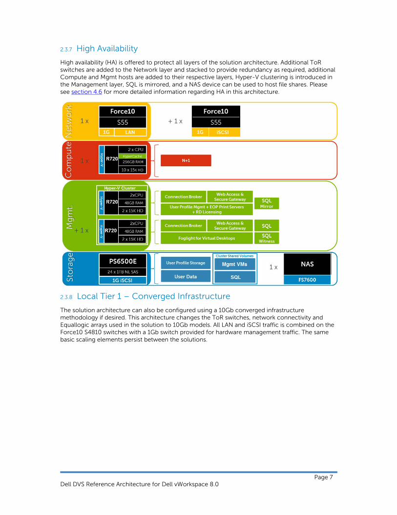
2.3.7 High Availability
High availability (HA) is offered to protect all layers of the solution architecture. Additional ToR switches are added to the Network layer and stacked to provide redundancy as required, additional Compute and Mgmt hosts are added to their respective layers, Hyper-V clustering is introduced in the Management layer, SQL is mirrored, and a NAS device can be used to host file shares. Please see section 4.6 for more detailed information regarding HA in this architecture.
2.3.8 Local Tier 1 – Converged Infrastructure
The solution architecture can also be configured using a 10Gb converged infrastructure methodology if desired. This architecture changes the ToR switches, network connectivity and Equallogic arrays used in the solution to 10Gb models. All LAN and iSCSI traffic is combined on the Force10 S4810 switches with a 1Gb switch provided for hardware management traffic. The same basic scaling elements persist between the solutions.

Dell DVS Reference Architecture for Dell vWorkspace 8.0
Page 8
For more information about the Converged Infrastructure offering, please see Appendix B.
2.3.9 Solution Density Summary
Design Scale Management Hosts
Compute Hosts
RDSH Sessions
RDVH Sessions
HA
10 User POC 0 1 0 10 -
50 User / Pilot 0 1 120 or 50 -
Combined 1 1 120
and
85 +1 ToR Switch
+1 Compute
+1 Mgmt
+NAS
Distributed 1 1 230
or
230 +1 ToR Switch
+1 Compute
+1 Mgmt
+NAS
Scale out 1 22 5060
or
5060 +1 ToR switch
+1 Compute
+1 Mgmt
+NAS
2.4 Cabling Diagrams
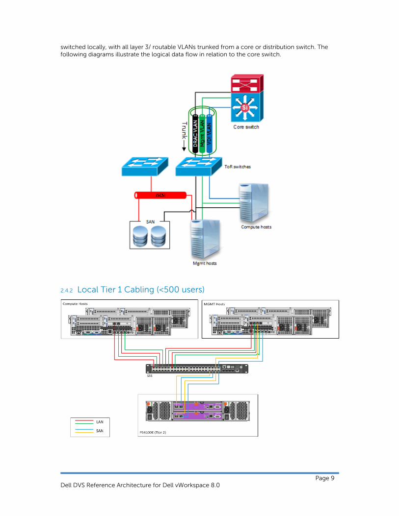
2.4.1 Local Tier 1 – Network Architecture
In the Local Tier 1 architecture, a single Force10 S55 switch can be shared among all network connections for both Management and Compute layer components, to the upper limit of 500 pooled VDI sessions. Over 500 users DVS recommends separating the network fabrics to isolate iSCSI and LAN traffic as well as making each network stack redundant. Only the Management servers connect to iSCSI storage in this model. All ToR traffic has been designed to be layer 2/
Dell DVS Reference Architecture for Dell vWorkspace 8.0
Page 9
switched locally, with all layer 3/ routable VLANs trunked from a core or distribution switch. The following diagrams illustrate the logical data flow in relation to the core switch.
2.4.2 Local Tier 1 Cabling (<500 users)

Dell DVS Reference Architecture for Dell vWorkspace 8.0
Page 10
3 Hardware Components
3.1 Network
The following sections contain the core network components for the DVS local Tier 1 solution. General uplink cabling guidance to consider in all cases is that TwinAx is very cost effective for short 10Gb runs and for longer runs fiber with SFPs should be used.
3.1.1 Force10 S55 (ToR Switch)
Model Features Options Uses
Force10 S55 44 x BaseT (10/100/1000) + 4 x SFP
Redundant PSUs ToR switch for LAN and iSCSI in Local Tier 1 solution 4 x 1Gb SFP ports the
support copper or fiber
12Gb or 24Gb stacking (up to 8 switches)
2 x modular slots for 10Gb uplinks or stacking modules
Guidance:
10Gb uplinks to a core or distribution switch are the preferred design choice using the rear 10Gb uplink modules. If 10Gb to a core or distribution switch is unavailable the front 4 x 1Gb SFP ports can be used.
The front 4 SFP ports can support copper cabling and can be upgraded to optical if a longer run is needed.
For more information on the S55 switch and Dell Force10 networking, please visit: LINK
3.1.1.1 Force10 S55 Stacking
The Top of Rack switches in the Network layer can be optionally stacked with additional switches, if greater port count or redundancy is desired. Each switch will need a stacking module plugged into a rear bay and connected with a stacking cable. Switch stacks greater than 2 should be cabled in a ring configuration with the last switch in the stack cabled back to the first. Uplinks should be configured on all switches in the stack back to the core to provide redundancy and failure

Dell DVS Reference Architecture for Dell vWorkspace 8.0
Page 11
protection.
Please reference the following Force10 whitepaper for specifics on stacking best practices and configuration: LINK
3.2 Servers
3.2.1 Local Tier 1 Rack
The server platform for the Dell vWorkspace solution is the best-in-class Dell PowerEdge R720. This dual socket CPU platform runs the fastest Intel Xeon E5-2600 family of processors, can host up to 768GB RAM, and supports up to 16 2.5” SAS disks. The Dell PowerEdge R720 offers uncompromising performance and scalability in a 2U form factor.
In the Local Tier 1 solution model, VDI sessions execute on the local storage of each Compute server. Due to the local disk requirement in the Compute layer, this model supports rack servers only. In this model only the Management server hosts require access to shared storage to support the solution’s Management role VMs. Because of this, the Compute and Management servers are configured with different add-on NICs to support their pertinent network fabric connection requirements. Refer to section 2.3.1 for cabling implications. The management server host has reduced RAM, CPU and fewer disks, since its VMs execute on shared Tier 2 storage.
Local Tier 1 Compute Host – PowerEdge R720
2 x Intel Xeon E5-2690 Processor (2.9Ghz)
256GB Memory (16 x 16GB DIMMs @ 1600Mhz) (VDI Hosts)
Or 128GB Memory (16 x 8GB DIMMs @ 1600Mhz) (RDSH Hosts)
Microsoft Windows Server 2012 Hyper-V
10 x 300GB SAS 6Gbps 15k Disks (OS + VDI)
PERC H710 Integrated 1GB RAID Controller – RAID10
Broadcom 5720 1Gb QP NDC (LAN)
Broadcom 5720 1Gb DP NIC (LAN)
iDRAC7 Enterprise w/ vFlash, 8GB SD
2 x 750W PSUs
10 x 2.5" SAS drives

Dell DVS Reference Architecture for Dell vWorkspace 8.0
Page 12
Local Tier 1 Management Host – PowerEdge R720
2 x Intel Xeon E5-2680 Processor (2.7Ghz)
48GB Memory (6 x 8GB DIMMs @ 1600Mhz)
Microsoft Windows Server 2012 Hyper-V
2 x 300GB SAS 6Gbps 15k Disks (OS)
PERC H710 Integrated 1GB RAID Controller – RAID1
Broadcom 5720 1Gb QP NDC (LAN/iSCSI)
Broadcom 5719 1Gb QP NIC (LAN/iSCSI)
iDRAC7 Enterprise w/ vFlash, 8GB SD
2 x 750W PSUs
For more information on the Dell PowerEdge R720 server and other server offerings from Dell, please visit: LINK
3.3 Storage
3.3.1 Equallogic Storage
3.3.1.1 PS4100E
Model Features Options Uses
Equallogic PS4100E
12 drive bays (NL-SAS/ 7200k RPM), dual HA controllers, Snaps/Clones, Async replication, SAN HQ, 1Gb, 2U chassis
12TB – 12 x 1TB HDs Tier 2 array for 1000 total users or less in local Tier 1 solution model (1Gb)
24TB – 12 x 2TB HDs
36TB – 12 x 3TB HDs
2 x 2.5" SAS drives

Dell DVS Reference Architecture for Dell vWorkspace 8.0
Page 13
For more information on the Dell Equallogic PS4100E and other networked storage options from Dell, please visit: LINK
3.3.1.2 PS6100E
Model Features Options Uses
Equallogic PS6100E
24 drive bays (NL-SAS/ 7200k RPM), dual HA controllers, Snaps/Clones, Async replication, SAN HQ, 1Gb, 4U chassis
14TB – 24 x 600GB HDs Tier 2 array for 1000+ users in local Tier 1 solution model (1Gb) 24TB – 24 x 1TB HDs
48TB – 24 x 2TB HDs
72TB – 24 x 3TB HDs
1Gb Ethernet ports Mgmt ports
12 x NL SAS drives

Dell DVS Reference Architecture for Dell vWorkspace 8.0
Page 14
3.3.1.3 PS6500E
Model Features Options Uses
Equallogic PS6500E
48 drive SATA/ NL SAS array, dual HA controllers, Snaps/Clones, Async replication, SAN HQ, 1Gb, 4U
48TB – 48 x 1TB SATA Tier 2 array for 2500+ users in Local Tier 1 solution model (1Gb) 96TB – 48 x 2TB SATA
144TB – 48 x 3TB NL SAS
3.3.1.4 NAS
3.3.1.5 FS7600
Model Features Scaling Uses
Equallogic FS7600
Dual active-active controllers, 24GB cache per controller (cache mirroring), SMB & NFS support, AD-integration. Up to 2 FS7600 systems in a NAS cluster (4 controllers).
1Gb iSCSI via 8 x Ethernet ports.
Each controller can support 1500 concurrent users, up to 6000 total in a 2 system NAS cluster.
Scale out NAS for Local Tier 1 to provide file share HA.

Dell DVS Reference Architecture for Dell vWorkspace 8.0
Page 15
3.4 Dell Wyse End Points
3.4.1 Display Choices for Dell Wyse Endpoints
3.4.2 Dell Wyse T10
The T10 handles everyday tasks with ease and also provides multimedia acceleration for task

Dell DVS Reference Architecture for Dell vWorkspace 8.0
Page 16
workers who need video. Users will enjoy integrated graphics processing and additional WMV & H264 video decoding capabilities from the Marvell ARMADA™ PXA 510 v7 1.0 GHz System-on-Chip (SoC). In addition, the T10 is one of the only affordable thin clients to support dual monitors with monitor rotation, enabling increased productivity by providing an extensive view of task work. Designing smooth playback of high bit-rate HD video and graphics in such a small box hasn’t been at the expense of energy consumption and heat emissions either. Using just 7 watts of electricity earns this device an Energy Star V5.0 rating. In addition, the T10’s small size enables discrete mounting options: under desks, to walls, and behind monitors, creating cool workspaces in every respect.
3.4.3 Dell Wyse D10D
The Dell Wyse D10D is a high-performance and secure ThinOS 8 thin client that is absolutely virus and malware immune. The D10D features an advanced dual-core AMD processor that handles demanding multimedia apps with ease and delivers brilliant graphics. Powerful, compact and extremely energy efficient, the D10D is a great VDI end point for organizations that need high-end performance but face potential budget limitations.
3.4.4 Dell Wyse D10D
Ultra-high performance in a compact package Power users and knowledge workers will love the

Dell DVS Reference Architecture for Dell vWorkspace 8.0
Page 17
exceptionally fast speed and power from the new dual-core driven D10D. With a 1.4 GHz AMD G series APU with integrated graphics engine, the D10D handles everything from demanding multimedia applications to business content creation and consumption with ease. The D10D even supports power users’ most demanding workloads: high quality audio and video, unified communications, CAD/CAM, 3D simulation and modeling, HD Flash and multimedia, and dual digital high resolution displays with rotation. Users will enjoy smooth roaming and super-fast 802.11 a/b/g/n wireless at 2.4 and 5 GHz with dual antennas. The D10D is Citrix HDX, Microsoft® RemoteFX, and VMware® Horizon View certified. It also supports legacy peripherals via an optional USB adapter. Averaging 9 watts, each and every D10D contributes – quietly and coolly – to lowering your organization’s carbon footprint, with reduced power usage and emissions.
3.4.5 Dell Wyse D90D8
A strong, reliable thin client, the D90D8 packs dual-core processing power into a compact form factor for knowledge workers who need performance for demanding virtual Windows® desktops and cloud applications. It’s also great for kiosks, and multi-touch displays in a wide variety of environments, including manufacturing, hospitality, retail, and healthcare. It features dual-core processing power and an integrated graphics engine for a fulfilling Windows® 8 user experience. Knowledge workers will enjoy rich content creation and consumption as well as everyday multimedia. Kiosk displays will look great on a thin client that is Microsoft RemoteFX®, Citrix® HDX, VMware PCoIP, and HD video enabled. Operating with less than 9 watts of energy, the D90D8 offers cool, quiet operations, contributing to lowering your overall carbon footprint.

Dell DVS Reference Architecture for Dell vWorkspace 8.0
Page 18
3.4.6 Dell Wyse Z90D8
The versatile Z90D8 gives people the freedom to mix and match a broad range of legacy and cutting edge peripheral devices. Ports for parallel, serial, and USB 3.0 offer fast, flexible connectivity. Like all Dell Wyse cloud clients, the new Dell Wyse Z90D8 is one cool operator. Its energy efficient processor – which out-performs other more power hungry alternatives – and silent fan-less design, all contribute to lowering an organization’s carbon footprint through power usage and emissions that are a fraction of traditional PC desktops.

Dell DVS Reference Architecture for Dell vWorkspace 8.0
Page 19
4 Solution Architecture for Dell vWorkspace
4.1 Overview
The Dell vWorkspace solution architecture follows a distributed model where solution components exist in layers. The Compute layer is where vWorkspace Desktop VMs and/or Remote Desktop Session Host VMs execute. The Management layer being dedicated to the vWorkspace management role VMs. Both layers, while inextricably linked, scale independently.
Solution Architecture Components
Hypervisor Microsoft Windows Server 2012 Hyper-V
VDI Broker vWorkspace 8.0 Premier Edition
Non-persistent provisioning
HyperDeploy 2.0
Database software Microsoft SQL Server 2012 (x64)
Server OS 3 x Microsoft Windows Server 2012 Standard edition license for Management Hosts
2 Microsoft Windows Server 2012 Standard edition licenses for Compute Hosts with RDSH VMs
1 x Microsoft Windows Server 2012 Standard edition license for Compute Hosts with Virtual Desktop VMs
Desktop OS Microsoft Windows 7 or 8 Enterprise (x86)
Desktop Virtual Machine Configuration
Hard Drive (Boot) IDE Controller
Hard Drive (Data) SCSI Controller
Disk Type VHDX – Dynamically Expanding
Smart Paging File Store with VM
Dynamic Memory (VDI) 512MB – Minimum, 2048MB – Maximum
4.1.1 vWorkspace Computer Group Options
Dell vWorkspace provides a number of delivery options to meet your needs, all within a single, simple, wizard-driven environment that is easy to set up and manage.
RD Session Host Sessions provide easy access to a densely shared session environment. vWorkspace RD Session Hosts can deliver full desktops or seamless application sessions

Dell DVS Reference Architecture for Dell vWorkspace 8.0
Page 20
from Windows Server Virtual Machines running Windows Server 2003 R2 (32 or 64 Bit), Windows Server 2008, (32 or 64 bit), R2 and 2012. RD Session Host Sessions are well suited for task based workers using office productivity and line of business applications, without needs for supporting complex peripheral devices or applications with extreme memory or CPU requirements.
Computer Groups Types – Computer Groups can be for virtual or physical computers running Windows XP Pro to Windows 8 Enterprise or Server 2003 R2 to 2012. Additionally there is limited support for Linux computer groups, but Linux is outside of the scope of this reference architecture.
o Desktop Cloud – provides users with access to a single virtual machine from a pool of available virtual machines on one or more non-clustered Hyper-V Servers with local storage. Desktop Clouds are elastic in nature and automatically expand as additional Hyper-V Compute Hosts are added to vWorkspace. New Compute Hosts automatically receive instant copies of the virtual machine templates, from which they provision new virtual machines locally. Desktop Cloud virtual machines are temporarily assigned to a user or device at logon, and at logoff are re-provisioned from the parent VHDX (instant copy of the virtual machine template). Desktop Cloud virtual machines are well suited for task based workers using office productivity and line of business applications.
o Temporary Virtual Desktop – are the non-persistent user desktop VMs traditionally associated with VDI. Each desktop VM is assigned a dedicated portion of the host server’s resources to guarantee the performance of each desktop. The desktop VM is dedicated to a single user or device while in use then returned to the computer group at logoff, or rebooted and reset to a pristine gold image state for the next user. Applications can be built into gold images or published via RemoteApps. A Microsoft VDA license is required for each non-Microsoft Software Assurance covered device accessing this type of environment.
o Persistent Virtual Desktop Groups – 1-to-1 desktop VMs assigned to a specific entitled user or device. All changes made by Personal VM users will persist through logoffs and reboots making this a truly personalized computing experience. A Microsoft VDA license is required for each non- Microsoft Software Assurance covered device accessing this type of environment.
o Physical Computers – Like Virtual Desktop Computer Groups, Physical Computers can be persistently or temporarily assigned to users or devices. Common use cases for connections to physical computers are remote software development and remote access to one’s office PC.
Please contact Dell or Microsoft for more information on licensing requirements for VDI.
4.2 Compute Server Infrastructure
The Compute host configuration varies slightly as to whether it will be hosting RDSH VMs or vWorkspace Desktops, or both. The vWorkspace Hyper-V Catalyst Components are automatically installed onto each Compute Host via the vWorkspace Management Console.
Up to 4 RD Session Host VMs may be provisioned to support up to 230 session-based users per Compute host.

Dell DVS Reference Architecture for Dell vWorkspace 8.0
Page 21
Up to 230 Windows 8 Enterprise VMs may be provisioned by vWorkspace on a single Compute host.
The requirements for RDSH VMs are outlined below. All applications and data should be installed within the system disk, to facilitate rapid provisioning via HyperDeploy.
Role vCPU Startup RAM (GB)
Dymanic Memory NIC OS + Data
vDisk (GB)
Tier 2 Volume (GB)
Min|Max Buffer Weight
RD Session Host 8 4 2GB | 31GB 20% Med 1 60 -
4.3 Management Server Infrastructure
The Management host configuration consists of VMs running in Hyper-V child partitions with the pertinent vWorkspace roles enabled. No vWorkspace roles need to be enabled in the parent partition of Management hosts, as the vWorkspace installer will enable any necessary roles. Please refer to the table below for the appropriate roles and number of server VMs required.
Hyper-V Architecture – Compute – RDSH
Hardware (CPU, RAM, hard disks)
Hyper-V Hypervisor
Parent Partition
Windows Server 2012
I/O Stack
Device Drivers
VSP
VMBus
Hyper-V Catalyst: -HyperCache-HyperDeploy
Child Partition
Windows Server 2012
VMBus
I/O Stack
Device Drivers
VSC
RDSH + Instant Provisioning Service
Child Partition
Windows Server 2012
VMBus
I/O Stack
Device Drivers
VSC
RDSH + Instant Provisioning Service
Child Partition
Windows Server 2012
VMBus
I/O Stack
Device Drivers
VSC
RDSH + Instant Provisioning Service
Child Partition
Windows Server 2012
VMBus
I/O Stack
Device Drivers
VSC
RDSH + Instant Provisioning Service
Hyper-V Architecture – Compute – VDI
Hardware (CPU, RAM, hard disks)
Hyper-V Hypervisor
Parent Partition
Windows Server 2012
I/O Stack
Device Drivers
VSP
VMBus
Hyper-V Catalyst: -HyperCache-HyperDeploy
Child Partition
Windows 8 Enterprise
VMBus
I/O Stack
Device Drivers
VSC
vWorkspace Tools + Instant Provisioning
Service
Child Partition
Windows 8 Enterprise
VMBus
I/O Stack
Device Drivers
VSC
vWorkspace Tools + Instant Provisioning
Serv ice
Child Partition
Windows 8 Enterprise
VMBus
I/O Stack
Device Drivers
VSC
vWorkspace Tools + Instant Provisioning
Serv ice
Child Partition
Windows 8 Enterprise
VMBus
I/O Stack
Device Drivers
VSC
vWorkspace Tools + Instant Provisioning
Serv ice

Dell DVS Reference Architecture for Dell vWorkspace 8.0
Page 22
Management role requirements for the base solution are summarized below. Data disks should be used for role-specific application files/ data, logs, IIS web files, etc and should exist in the Management volume on the Equallogic array. Please note that the Tier2 volume presented to the file server is designated as a pass-through disk (PTD).
Role vCPU Startup RAM (GB)
Dynamic Memory NIC OS vDisk (GB)
Tier 2 Volume (GB)
Min|Max Buffer Weight
vWorkspace Connection Broker
2 4 512MB|8GB 20% Med 1 40 -
Foglight for Virtual Desktops
1 4 512MB|6GB 20% Med 1 60 -
vWorkspace Web Access & Secure Gateway
2 4 512MB|6GB 20% Med 1 40 -
vWorkspace Profiles, Universal Print Server & Microsoft RD Licensing
2 4 512MB|6GB 20% Med 1 60 -
File Server 1 4 512MB|6GB 20% Med 1 40 2048 (PTD)
SQL Server 2 8 512MB|10GB 20% Med 1 40 210 (NTFS)*
TOTALS 10 28 6 240 2158
*Refer to section 4.4.3 for more information about specific volumes required.
4.4 Storage Architecture
4.4.1 Local Tier 1
In this model, Tier 1 storage exists as local hard disks on the Compute hosts. A single RAID10 Array is used for the Local Server OS and provisioned desktop VMs along with their respective write caches. Virtual disks within the RAID controller configuration should be defined to separate the OS from the VDI volumes. To achieve the required performance level and redundancy, RAID 10 must be used across all 10 local disks used for storing the Virtual Hard Disks. Increased IO performance is provided via the 1GB cache module on the H710 RAID controller.
Volumes Size (GB) RAID Storage Array Purpose File System
OS 100 1 Tier 1 Host Operating System NTFS
VDI 1000 10 Tier 1 Pooled + Shared VDI NTFS
Hyper-V Architecture – Mgmt
Hardware (CPU, RAM, hard disks)
Hyper-V Hypervisor
Child Partition
Windows Server 2012
VMBus
I/O Stack
Device Drivers
VSC
vWorkspace Mgmt Roles
Child Partition
Windows Server 2012
VMBus
I/O Stack
Device Drivers
VSC
vWorkspace Connection Broker
Parent Partition
Windows Server 2012
VMBus
I/O Stack
Device Drivers
VSC
Child Partition
Windows Server 2012
VMBus
I/O Stack
Device Drivers
VSC
File, SQL, etc

Dell DVS Reference Architecture for Dell vWorkspace 8.0
Page 23
Volumes Size (GB) RAID Storage Array Purpose File System
<Spare> 400 - Tier 1 Expansion for OS or VDI -
4.4.2 vWorkspace Hyper-V Catalyst Components (HCC)
vWorkspace Hyper-V Catalyst Components are installed by vWorkspace in the Parent Partition of the Hyper-V Server hosting non-persistent Virtual Desktops or RD Session Host Virtual Machines. HCC includes the following features:
HyperCache is an in RAM IO Cache in the Hyper-V Parent Partition that dramatically reduces the IO requirements of the disk subsystem. HyperCache typically reduces the number of hard disk spindles required to deliver optimal performance by 40%, and improves the perceived user experience as writes are optimized and most reads come directly from RAM.
HyperDeploy offers instantaneous VM Template Replication and versioning for Hyper-V.
4.4.3 Shared Tier 2
Tier 2 is shared iSCSI storage used to host the Management server VMs and user data. The Equallogic 4100E array can be used for smaller scale deployments, with the 6100E and 6500E arrays used for larger deployments. Intent to scale should be considered when making the initial investment. The table below outlines the minimum volume requirements for Tier 2 storage. Larger disk sizes and additional volumes can be chosen to meet the capacity needs of the customer. The user data volume can be presented either via a VHDX or native NTFS pass-through disk to simplify a future upgrade to NAS. All vWorkspace management VM disks should be presented as VHDX.
Volumes Size (GB)
RAID Storage Array
Purpose File System
Management 500 50 Tier 2 vWorkspace Infrastructure VMs, File
Server
NTFS
SQL Data 100 50 Tier 2 SQL NTFS
SQL Logs 100 50 Tier 2 SQL NTFS
TempDB Data
5 50 Tier 2 SQL NTFS
TempDB Logs
5 50 Tier 2 SQL NTFS
User Data* 2048 50 Tier 2 File Server NTFS
User Profiles (1-2MB Per User is
Typical) 5 50 Tier 2 User profiles NTFS
Templates/ ISO
200 50 Tier 2 ISO/ gold image storage (optional)
NTFS
*User data volumes should be adjusted to suit the needs of the customer.

Dell DVS Reference Architecture for Dell vWorkspace 8.0
Page 24
4.4.4 Virtual Hard Disk Format
In vWorkspace 8.0 the recommended Virtual Hard Disk format is VHDX. When vWorkspace replicates the VHDX from the Master VM to each of the Compute Hosts, HyperDeploy creates an instant copy of the original VHDX in a powered-off state that is requested by each Compute Host in the environment. Each Compute host will serve virtual desktops based on this replicated master image. Fixed or Dynamically Expanding VHDX formatting is ultimately less important in the vWorkspace environment as vWorkspace HyperDeploy only copies the used portions from the master VM to the Parent VHDX of each Compute Host. The “Parent VHDX” is the terminology vWorkspace uses for the disk that is replicated to each Compute host, from which new VMs and Differencing Disks are created. New Virtual Machines never reference the VHDX of the master VM, but rather reference an instant copy that is presented on each Compute host as the Parent VHDX.
The VHDX disk format provides numerous advantages over the older VHD specification and should be used for all virtual disks in the solution. Larger vDisk support, up to 64TB, corruption protection during power failures, and larger sector disk alignment are a few of the new features.
In default form, new VHDX files created from within Hyper-V are created with a 32MB block size, 4096B physical sector size and a 512B logical sector size. This results in a rapidly growing differencing disk that will increase up to 3GB in a short period of time.
Creating new VHDX files using the following PowerShell script will keep VHDX and differencing disk sizes low and more in line with what was experienced using the older VHD standard.
new-vhd -path "d:\<path to VHDX>\<VM name>.vhdx" -dynamic -SizeBytes 25GB -LogicalSectorSizeBytes 512 -PhysicalSectorSizeBytes 512 -BlockSizeBytes 2MB
4.4.5 DNS
DNS plays a crucial role in the environment not only as the basis for Active Directory but will be used to control access to the various Microsoft software components. All hosts, VMs, and consumable software components need to have a presence in DNS, preferably via a dynamic and AD-integrated namespace. Microsoft best practices and organizational requirements should be adhered to.
To plan for eventual scaling, access to components that may live on one or more servers should be considered during initial deployment. The use of CNAMEs and the round robin DNS mechanism should be employed to provide a front-end “mask” to the back-end server actually hosting the service or data source.
4.4.6 SQL Server
SQL Server is required to store vWorkspace configuration information. In environments fewer than 2500 seats SQL Server Express can be used to minimize licensing costs. This architecture provides configuration guidance using a dedicated SQL Server VM to serve the environment.
4.4.7 File Services
The File Services role will be provided via a dedicated VM. In the interest of portability and providing a clean path to an optional HA upgrade, the volumes can be presented to the file server VM in the form of a Pass-Through Disk. This will ensure a cleaner transition for customers who upgrade to HA and add a NAS head to their environments by keeping the data on the storage array and not inside a VHD that will need to be copied out.
4.4.8 vWorkspace User Profile Management
User Profile Management is a component of the vWorkspace solution which is used to manage user profiles. vWorkspace provides a cohesive method to manage user settings in a VDI and/or RD Session Host environment. The solution file server will be used to host the vWorkspace User Profile Storage Service storage location, as well as Desktop and My Documents data that shall be

Dell DVS Reference Architecture for Dell vWorkspace 8.0
Page 25
redirected to dedicated shares via Group Policy.
4.5 Foglight for Virtual Desktops Foglight™ for Virtual Desktops brings powerful diagnostics, rich visualization and reporting to vWorkspace. Built on Dell’s popular and industry-proven Foglight monitoring platform, Foglight for Virtual Desktops monitors Dell vWorkspace VDI and Terminal Server/RemoteDesktop Session Host (TS/RDSH) implementations providing IT with the real-time and historical data needed to keep these deployments running at peak performance. Foglight for Virtual Desktops goes well beyond merely alerting you to problems — it also provides diagnostics and analytics so you can identify and resolve VDI and TS/RDSH issues before they impact users. Please see Appendix D for more information.

Dell DVS Reference Architecture for Dell vWorkspace 8.0
Page 26
Monitoring end user experience uniquely provides the capability to stay on top of the performance of your environment as it pertains specifically to the end user. Keep end users happy by fixing VM problems before they are impacted!
4.6 Hyper-V Configuration
The Local Tier 1 solution for Dell vWorkspace is built upon the Server 2012 Hyper-V hypervisor. All Microsoft best practices and prerequisites should be adhered to (NTP, DNS, Active Directory, etc).

Dell DVS Reference Architecture for Dell vWorkspace 8.0
Page 27
4.6.1 Core Components
Each Compute and Management host will run the full GUI version of Server 2012 in this solution. All vWorkspace component roles will exist as VMs yielding a100% virtualized architecture in both Compute and Management server layers. RD Session Hosts will be provisioned by vWorkspace on the Compute hosts, while the vWorkspace management components will be enabled in dedicated VMs on the Management hosts. The vWorkspace Hyper-V Catalyst Components will be enabled in the parent partition of all Compute hosts as discussed in section 4.2.
4.6.2 Hyper-V Networking (Local Tier 1)
The network configuration in this model will vary slightly between the Compute and Management hosts. The Compute hosts do not need access to iSCSI shared storage since they are hosting the VDI sessions on local disk. The following outlines the VLAN requirements for the Compute and Management hosts in this solution model:
Compute hosts (Local Tier 1)
o Management VLAN: Configured for Hyper-V infrastructure traffic – L3 routed via
core switch
o VDI VLAN: Configured for VDI session traffic – L3 routed via core switch
Management hosts (Local Tier 1)
o Management VLAN: Configured for Hyper-V Management traffic – L3 routed via
core switch
o iSCSI VLAN: Configured for iSCSI traffic – L2 switched only via ToR switch
o VDI Management VLAN: Configured for VDI infrastructure traffic – L3 routed via
core switch
An optional DRAC VLAN can be configured for all hardware management traffic, which
should be L3 routed via core switch
In this solution architecture, LAN and iSCSI traffic will be segmented in dedicated VLANs and discrete switch stacks for solutions over 500 users. Each Local Tier 1 Compute host will have a quad port NDC as well as an add-on 1Gb dual port PCIe NIC. The LAN traffic from the server to the ToR switch should be configured as a LAG to maximize bandwidth. The Compute hosts will require 2 Virtual Switches, one for VDI LAN traffic, and another for the Hyper-V Management.
RD Session Host Groups
Persistent Computer Groups
Cloud Computer Group
Physical Computer Groups
vWorkspaceConnection Broker
vWorkspaceWeb Access
vWorkspaceSecure Gateway
RD Licensing
SQL ServerFoglight for Virtual
DesktopsvWorkspace User Profile
Storage Service

Dell DVS Reference Architecture for Dell vWorkspace 8.0
Page 28
The Management hosts have a slightly different configuration since they will additionally access iSCSI storage. The add-on NIC for the Management hosts will be a 1Gb quad port NIC. 3 ports of both the NDC and add-on NIC will be used to form 3 virtual switches. iSCSI should be isolated onto its own vSwitch with teamed NICs and connections from all 3 vSwitches should pass through both the NDC and add-on NIC per the diagram below. Care should be taken to ensure that all vSwitches are assigned redundant NICs that are NOT from the same PCIe device. The LAN traffic from the server to the ToR switch should be configured as a LAG. VLAN IDs should be specified in all virtual switches used within the Compute layer Hyper-V host.
NIC teaming should be configured in the Hyper-V host using Dell drivers or native Windows NIC teaming to ensure that the proper NICs from differing PCIe devices are bonded. The resulting teamed virtual NIC should then be assigned to the appropriate virtual switch within Hyper-V. VLAN IDs should be specified in all virtual switches used within the Management layer Hyper-V host. All NICs and switch ports should be set to auto negotiate.
vsw1LAN
vsw0Mgmt
1Gb QP NDC
R720
1Gb DP NIC
Compute Hosts – Local Tier1
S55 - LAN
ToR
vsw2LAN
vsw1iSCSI
R720
Mgmt Hosts – Local Tier1
vsw0Mgmt
S55 - LAN
S55 - iSCSI1Gb QP NIC
1Gb QP NDC
ToR

Dell DVS Reference Architecture for Dell vWorkspace 8.0
Page 29
4.7 Solution High Availability
Each layer in the solution architecture can be individually protected to prevent an extended service outage. The Network layer only requires an additional switch configured in a stack for each discrete switch stack. Please refer to section 3.1.1.1 that covers Force10 switch stacking.
Protecting the Compute layer for RDSH and vWorkspace Desktops is provided by adding an additional host to a group, thus effectively increasing the hosting capacity of a given group. Session requests will be fulfilled by all hosts in the group and as a result, each will have reserve capacity to insure against a host failure. Care needs to be taken to ensure that user provisioning does not exceed the overflow capacity provided by the additional node. vWorkspace provides Load Evaluators that can be assigned to Compute Hosts to ensure that the hosts are not overcommitted.
To implement HA for the Management layer, we will also add an additional host but will add a few more layers of redundancy. The following will protect each of the critical infrastructure components in the solution:
The Management hosts will be configured in a Hyper-V cluster (Node and Disk Majority).
Local Tier 1 – Compute HA
vWorkspace Connection Broker
N+1
Manage 3000-5000 VMs each (2 brokers for HA)

Dell DVS Reference Architecture for Dell vWorkspace 8.0
Page 30
The shared storage volume that hosts the Management VMs will be upgraded to a Cluster Shared Volume (CSV).
SQL mirroring should be configured to further protect SQL.
vWorkspace Connection Brokers natively operate in HA mode, no clustering or load balancing needs to be added for the broker specifically, but the SQL Server Configuration DB must be HA.
The following storage volumes are applicable in a 2-node Management layer HA scenario:
Volumes Host Size (GB)
RAID Storage Array
Purpose File System CSV
Management 1 500 50 Tier 2 vWorkspace Infrastructure
NTFS Yes
Management 2 500 50 Tier 2 vWorkspace Infrastructure
NTFS Yes
SQL Data 2 100 50 Tier 2 SQL Data Disk NTFS Yes
SQL Logs 2 100 50 Tier 2 SQL Logs Disk NTFS Yes
SQL TempDB Data
2 5 50 Tier 2 SQL TempDB Data Disk NTFS Yes
SQL TempDB Logs
2 5 50 Tier 2 SQL TempDB Logs Disk NTFS Yes
SQL Witness 1 1 50 Tier 2 SQL Witness Disk NTFS Yes
Quorum 1 - 500MB 50 Tier 2 Hyper-V Cluster Quorum NTFS Yes
User Data - 2048 50 Tier 2 File Server NTFS No
User Profiles - 20 50 Tier 2 User profiles NTFS No
Templates/ ISO
- 200 50 Tier 2 ISO/ gold image storage (optional)
NTFS Yes
For more information on vWorkspace Broker Scalability, please follow this link: LINK
4.7.1 SQL Database HA
HA for SQL Server 2012 is provided via an optional 3-server synchronous mirror configuration that includes a witness (High safety with automatic failover). This configuration will protect all critical data stored within the database from physical server as well as virtual server problems. The principal

Dell DVS Reference Architecture for Dell vWorkspace 8.0
Page 31
VM that will host the primary copy of the data should exist on the first Mgmt host. The mirror and witness VMs should exist on the second or later Mgmt hosts. All critical databases should be mirrored to provide HA protection.
There are a number of steps required to successfully set up SQL mirroring per Microsoft and Dell best practices. Please refer to the Dell vWorkspace 8.0 product documentation for more information on supported configurations.
Please refer to the following Dell Quest support article for more information: LINK
4.8 Disaster Recovery and Business Continuity
DR and BC can be achieved natively via Hyper-V Replicas. This technology can be used to replicate VMs from a primary site to a DR or BC site over the WAN asynchronously. Hyper-V Replicas are unbiased as to underlying hardware platform and can be replicated to any server, network, or storage provider. Once the initial replica is delivered from the primary site to the replica site, incremental VM write changes are replicated using log file updates. Multiple recovery points can be stored and maintained, using snapshots, to restore a VM to a specific point in time.

Dell DVS Reference Architecture for Dell vWorkspace 8.0
Page 32
4.9 vWorkspace Data Flow
4.10 Conclusion
The Dell vWorkspace solution provides a robust and scalable VDI platform for pooled, personal and Session based deployments. Using VDI-optimized hardware in a configuration that has been validated and proven by Dell DVS Engineering, you can deploy vWorkspace based VDI that is both cost effective and high performing. Our layered architecture provides flexibility to maximize your infrastructure investment with the capability to expand and contract where necessary.

Dell DVS Reference Architecture for Dell vWorkspace 8.0
Page 33
Appendix A – Dell DVS 10-Seat Trial Kit
The 10 User POC bundle was purpose-built to provide high performance VDI using a modicum of infrastructure. Only 11 x 1Gb Ethernet ports are required (1 x server + 10 x end points) which can be provided using existing customer network infrastructure. If suitable network capacity is not in place, Dell recommends using a Force10 S55 1Gb switch.
Server Configuration The PowerEdge T110 II is the server platform of choice for this offering, providing high performance at an extremely low price of entry. Supporting the Intel Xeon E3-1200 series of CPUs and up to 32GB RAM, the T110 provides a solid server platform to get started with VDI.
All VDI server roles and desktop sessions are hosted on a single server in this model so there is no need for external storage. Higher scale and HA options are not offered with this bundle.
10 User Compute Host – PowerEdge T110 II
1 x Intel Xeon E3-1220 V2 (3.1Ghz)
32GB Memory (4 x 8GB DIMMs @ 1600Mhz) (VDI)
Microsoft Windows Server 2012 Hyper-V
4 x 500GB SATA 7.2k Disks RAID 10 (OS + VDI)
PERC H200 Integrated RAID Controller
Broadcom 5722 1Gb NIC (LAN)
305W PSU

Dell DVS Reference Architecture for Dell vWorkspace 8.0
Page 34
Based on the server hardware configuration, 10 users will experience excellent performance with additional resource headroom available in reserve. The consumption numbers below are based on average performance:
Task Worker Users
CPU (%) RAM (GB Consumed)
Disk (IOPS)
Network (Kbps)
10 72 20 77 150
Management and Compute Infrastructure The solution architecture for the 10 user POC bundle combines the Compute, Management, and Storage layers onto a single server-based platform. To maximize server resources, the connection broker and license server roles are enabled within the Hyper-V parent partition, while the File server and VDI sessions exist as VMs within child partitions.
As is the case in the larger distributed architecture, no roles will be enabled within the Hyper-V parent partition. All VDI management roles and VDI sessions will be enabled via VMs running in child partitions. A single Windows Server VM is sufficient to run the VDI mgmt. portions.

Dell DVS Reference Architecture for Dell vWorkspace 8.0
Page 35
Role vCPU Startup RAM (GB)
Dynamic Memory NIC OS + Data
vDisk (GB)
Tier 2 Volume (GB)
Min|Max Buffer Weight
VDI Mgmt VM 1 4 512MB|8GB 20% Med 1 40 50
Pooled VDI VMs 1 512MB 512MB|2GB 20% Med 1 20 -
Storage Configuration The 10 User POC solution includes 4 total hard drives configured in RAID10 to host the Windows Server OS as well as VDI sessions. This configuration will maximize available performance and data protection.
Volumes Size RAID Storage Purpose File System
OS + VDI 1TB 10 Tier 1 Host OS/ Mgmt roles + VDI Sessions
NTFS

Dell DVS Reference Architecture for Dell vWorkspace 8.0
Page 36
Appendix B – Converged Infrastructure
The Dell DVS Reference Architecture for Dell vWorkspace 8.0 also offers a 10Gb converged infrastructure (CI) option. CI reduces the number of switch ports required, while dramatically increasing the available bandwidth and reducing cabling. Using CI in this solution architecture requires small changes to be made in each layer of the solution.
In the network layer, the 1Gb Force10 S55 switch is used to host hardware management traffic (iDRAC) only. 10Gb LAN and iSCSI are hosted together on a stacked pair of Force10 S4810 switches configured in a VLT.
The Compute layer remains largely the same with only a change required for the server NICs to 10Gb. The Compute hosts will connect to the same S4810 stack as the Mgmt hosts, but only LAN traffic will be sent to and from these hosts. All scaling and session hosting guidance does not change.
The Mgmt hosts will also require 10Gb NICs with both LAN and iSCSI traffic traversing the same interfaces. All vWorkspace-specific scaling does not change.
Lastly the Storage tier will be upgraded to a like 10Gb model and will serve the same purpose: Tier 2 storage.
The rest of the solution sizing and guidance is completely interchangeable.

Dell DVS Reference Architecture for Dell vWorkspace 8.0
Page 37
Logical network architecture for converged infrastructure:
DR
AC
VLA
N
Mg
mt V
LAN
Mgmt hosts
Compute hosts
Core switch
ToR switches
Tru
nk
SANV
DI V
LAN
iSC
SI V
LAN

Dell DVS Reference Architecture for Dell vWorkspace 8.0
Page 38
Appendix C – vWorkspace Desktop Cloud
Performance Analysis Results (non-persistent VMs)
Performance analysis of the above architecture was carried out using Login VSI software. Login VSI is a widely used tool to generate workloads that are representative of typical corporate IT users of centralized desktop environments such as Server Based Computing (SBC) and Virtual Desktop Infrastructure (VDI). The workload produced by Login VSI for the current performance analysis effort was representative of a typical set of activities performed by (i) a task worker (the basic workload) and (ii) a knowledge worker (the standard workload). Resource utilisation on the compute node was monitored using Microsoft best practices for measuring performance on Hyper-V as detailed at:
http://technet.microsoft.com/en-us/library/cc768535.aspx
In addition to the above, end-user experience was monitored using the Liquidware Labs Stratusphere UX tool. This tool provides comprehensive information (including reports and charts) for IT personnel in relation to end-user experience in a centralized desktop environment; among these charts is a “golden quadrant” type chart, which aggregates parameters that contribute to the end-user experience seen by a centralized desktop environment user into a single chart; this is the chart used during the current performance analysis activity.
For the task worker scenario, the performance analysis scenario used was to pre-boot all virtual desktops and then login 230 task worker (basic) workloads using a login interval of 30 seconds. Once all users have logged in, all 230 users run workload activities at steady-state for 60 minutes and then logoffs commence. For the knowledge worker scenario, a similar test methodology was used with the standard workload and 170 users.
It should be noted that in order to replicate a real corporate user environment, an enterprise-level anti-virus infrastructure was deployed, with McAfee VirusScan Enterprise 8.8 installed on all virtual desktops and McAfee ePolicy Orchestrator 4.5 used for management and deployment purposes.
Additionally, vWorkspace Computer Groups were configured in Desktop Cloud mode, whereas users logged off, their temporarily assigned VM was powered-off, deleted, re-provisioned and powered on during the existing workload. User’s profile data was merged into each session at logon via vWorkspace User Profile Management and extracted at logoff. These were done to emulate real world usage of vWorkspace, as opposed to trying to get the maximum number of sessions on a server by way of over-tuning.

Dell DVS Reference Architecture for Dell vWorkspace 8.0
Page 39
Configuration Summary – Workload Independent Settings
The table shown below summarizes the important configuration information in relation to the pooled VDI environment used for performance analysis of both the task and knowledge worker scenarios.
vWorkspace client settings were configured indicative of a production deployment, using standard Connection Policies in the vWorkspace Management Console to control the user experience. All tests (unless otherwise stated) had the following features enabled:
EOP Multimedia Redirection
EOP Flash Redirection
EOP Graphics Acceleration (enabled for Internet Explorer and PowerPoint)
User Profile Management
Solution Configuration – Software Components Description/Version vWorkspace Version 8.0 Hypervisor Hyper-v 2012 Microsoft SQL Server Version 2012 Enterprise Edition (64-Bit) Windows 8 Enterprise 32Bit VDI Clients for characterization tests
Login VSI launchers Windows Server 2012 Standard VMs for hosting vWorkspace, MSSQL server
and other infrastructure VMs. Below is the Solution Hardware Configuration. For additional configuration information see the reference architecture document.
Solution Configuration - Hardware Components: Description
Virtual Desktops 1 x Dell PowerEdge R720Servers:
o Server 2012 Hyper-v
o 2 x 8-Core Intel® Xeon® E5-2690 2.9 Ghz Processors
o 256 GB RAM
o 10 x 146GB 15K SAS internal disk drives
o 1 x Broadcom 5720 1 GbE NIC, Quad port
o PERC H710 1GB RAID Controller
Windows Server 2012 was installed and configured on the R720 Compute Host server.
Enabled Hyper-v role on the server which will act as Hypervisor to host virtual environment
Virtual Desktops VMs: Windows 8 Enterprise (32 Bit)

Dell DVS Reference Architecture for Dell vWorkspace 8.0
Page 40
vWorkspace 8.0 Infrastructure Server
1 x Dell PowerEdge R720 Server:
o Server 2012 Hyper-v
o 2 x 8-Core Intel® Xeon® E5-2690 2.9 Ghz Processors
o 32 GB RAM
o 2 x 146GB 15K SAS internal disk drives
o 1 x Broadcom 5709 1GbE NIC, Quad-Port
Windows Server 2012 was installed and configured on the R720 Compute Host server
Six Infrastructure VMs installed and configured to host roles shown below.
The VMs are loaded with Windows 2012 operating system.
Each VM hosted the following services:
vWorkspace 8.0
Foglight
Microsoft SQL server
RDSH Server
Web Server
File Server
Test results and analysis The primary focus of the tests is to determine the maximum number of desktops that can be deployed with vWorkspace without compromising performance. All tests included a single Management Server along with a single Compute host, for hosting virtual desktops. To determine the density data all tests were conducted on the Compute host. The virtual desktops created using vWorksapce are placed on local Tier 1 storage on each Compute host.
The primary objectives of the testing are:
Determine the CPU, Memory, Disk and Network impacts of integrating vWorkspace using
the Basic and Standard LoginVSI workloads.
Determine the performance impact of the vWorkspace on the local disks during peak I/O
activity such as boot storms and login storms.
Test 1: 230 Task Worker Users (Light)
The light workload runs a small number of applications that are representative of applications used by typical task workers (e.g. call center). The applications are closed immediately after use, resulting in relatively low memory and CPU consumption when compared to the standard workload. The applications used are Internet Explorer, Microsoft Word and Microsoft Outlook, with only 2 of these applications used simultaneously. The user idle time is approximately 17% of total run time.
The following validation was done for 230 light users on an R720 host with 2.9 GHz processors and 10 x 146GB 15K disks. Validation was performed using the DVS standard testing methodology leveraging Login VSI to manage the desktop cloud with stratosphere UX and Windows Performance Monitor to deliver performance results. The CPU usage for this test reached a reasonable 84.39% at peak, confirming that the Compute host with this configuration can support up to 230 basic users with acceptable head room in reserve.
The graphs below show the CPU, Active memory, Local Tier 1 disk IOPS, Network and VDI UX

Dell DVS Reference Architecture for Dell vWorkspace 8.0
Page 41
scatter plot results from this validation.
As seen from the following graph (Figure1), maximum CPU utilization was approximately 84.39%. After all users started logging in, CPU usage spiked from 10 to 90% and became stable between 74-84% once all users logged in, it then dropped as the users logged off.
Figure 1
A Spike is evident after all VMs start logging in however active memory is about 86.7% of available memory during the peak of validation activity providing sufficient reserve.
Figure 2
As seen from the graph below, overall network performance was very good with very low overall consumption.
0
20
40
60
80
100
1209:27 AM
9:40 AM
9:53 AM
10:06 AM
10:19 AM
10:32 AM
10:45 AM
10:58 AM
11:11 AM
11:24 AM
11:37 AM
11:50 AM
12:03 PM
12:16 PM
12:29 PM
12:42 PM
12:55 PM
1:08 PM
1:21 PM
1:34 PM
CPU
CPU
0
50
100
150
200
250
9:27 AM
9:42 AM
9:57 AM
10:12 AM
10:27 AM
10:42 AM
10:57 AM
11:12 AM
11:27 AM
11:42 AM
11:57 AM
12:12 PM
12:27 PM
12:42 PM
12:57 PM
1:12 PM
1:27 PM
1:42 PM
Active Memory
Active Memory

Dell DVS Reference Architecture for Dell vWorkspace 8.0
Page 42
Figure 3
A Spike is evident after all VMs start logging in however the read/write activity was fluctuating from 09:27 AM to 11:07 AM and became stable after all users finished logging in from 11:08 AM to 12:46 PM. Total Peak IOPS measured during the login state was 2194 giving an IOPS value of 9.53 per user and total peak IOPS in steady state (after all users logged in) was 1268 giving an IOPS value of 5.50 per user.
Figure 4
From the graph below we can see that 229 out of 230 sessions registered perfect performance, while all registered in the ideal upper right-hand quadrant. This is well within the acceptable tolerance for this test.
0200000400000600000800000
100000012000001400000160000018000002000000
9:27 AM
9:44 AM
10:01 AM
10:18 AM
10:35 AM
10:52 AM
11:09 AM
11:26 AM
11:43 AM
12:00 PM
12:17 PM
12:34 PM
12:51 PM
1:08 PM
1:25 PM
1:42 PM
Total Bytes/Sec
Total Bytes/Sec
0
500
1000
1500
2000
2500
9:27 AM
9:41 AM
9:55 AM
10:09 AM
10:23 AM
10:37 AM
10:51 AM
11:05 AM
11:19 AM
11:33 AM
11:47 AM
12:01 PM
12:15 PM
12:29 PM
12:43 PM
12:57 PM
1:11 PM
1:25 PM
1:39 PM
Reads/sec
Writes/Sec

Dell DVS Reference Architecture for Dell vWorkspace 8.0
Page 43
Figure 5
Test 2: 170 Knowledge Worker Users (Medium)
The medium workload runs a number of applications that are representative of applications used by knowledge workers (e.g. accountants). The applications used are Internet Explorer, a number of Microsoft Office applications (Excel, Outlook, PowerPoint and Word), Adobe Acrobat Reader, Bullzip PDF printer and 7-zip file compression software. Relative to the task worker workload discussed above, idle time is slightly lower as a percentage of overall runtime and a maximum of 5 applications are open simultaneously (compared to 2 for the task worker).
The following validation was done for 170 medium users on an R720 host with 2.9 GHz processors and 10 x 146GB 15K disks. Validation was performed using DVS standard testing methodology leveraging Login VSI to manage the desktop cloud with stratusphere UX and Windows Performance Monitor to deliver the performance results. The CPU usage for this test reached 85% at peak, confirming that the Compute host with this configuration can support up to 170 medium users with acceptable head room in reserve.
The following graphs show the CPU, Active memory, Local Tier 1 disk IOPS, Network and VDI UX scatter plot results from this validation.

Dell DVS Reference Architecture for Dell vWorkspace 8.0
Page 44
As seen from the graph below, the maximum CPU utilization was approximately 77%. After all users started logging in, CPU usage was spiked from 10 to 78% and became stable between 60-70% once all users logged in, then dropped as the users logged off.
Figure 6
A Spike is evident after all VMs start logging in however active memory is about 80% of available memory during the peak of validation activity.
Figure 7
As seen from the following graph, overall network performance was very good with low overall bandwidth required.
0
10
20
30
40
50
60
70
80
90
3:38 PM
3:48 PM
3:58 PM
4:08 PM
4:18 PM
4:28 PM
4:38 PM
4:48 PM
4:58 PM
5:08 PM
5:18 PM
5:28 PM
5:38 PM
5:48 PM
5:58 PM
6:08 PM
6:18 PM
6:28 PM
6:38 PM
6:48 PM
6:58 PM
CPU
CPU
0
50
100
150
200
250
3:38 PM
3:50 PM
4:02 PM
4:14 PM
4:26 PM
4:38 PM
4:50 PM
5:02 PM
5:14 PM
5:26 PM
5:38 PM
5:50 PM
6:02 PM
6:14 PM
6:26 PM
6:38 PM
6:50 PM
7:02 PM
Active Memory
Active Memory

Dell DVS Reference Architecture for Dell vWorkspace 8.0
Page 45
Figure 8
A Spike is evident after all VMs start logging in however the read/write activity was fluctuating from 03:38 PM to 05:07 PM and became stable after all users finished logging in from 05:07 PM to 05:57 PM. Total Peak IOPS measured during the login state was 1589 giving an IOPS value of 9.34 per user and total peak IOPS measured during the steady state (after all users logged in) was 924 giving an IOPS value of 5.43 per user.
Figure 9
From the graph below we can see that 165 out of 170 sessions registered perfect user experience which is within the acceptable tolerance for this test.
0
2000000
4000000
6000000
8000000
10000000
12000000
3:38 PM
3:52 PM
4:06 PM
4:20 PM
4:34 PM
4:48 PM
5:02 PM
5:16 PM
5:30 PM
5:44 PM
5:58 PM
6:12 PM
6:26 PM
6:40 PM
6:54 PM
Total Bytes/Sec
Total Bytes/Sec
0
200
400
600
800
1000
1200
1400
1600
3:38 PM
3:49 PM
4:00 PM
4:11 PM
4:22 PM
4:33 PM
4:44 PM
4:55 PM
5:06 PM
5:17 PM
5:28 PM
5:39 PM
5:50 PM
6:01 PM
6:12 PM
6:23 PM
6:34 PM
6:45 PM
6:56 PM
Reads/Sec
Writes/sec
Dell DVS Reference Architecture for Dell vWorkspace 8.0
Page 46
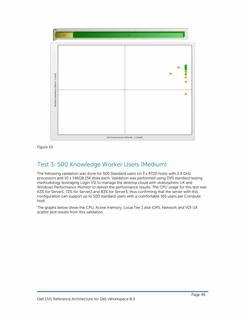
Figure 10
Test 3: 500 Knowledge Worker Users (Medium)
The following validation was done for 500 Standard users on 3 x R720 hosts with 2.9 GHz processors and 10 x 146GB 15K disks each. Validation was performed using DVS standard testing methodology leveraging Login VSI to manage the desktop cloud with stratosphere UX and Windows Performance Monitor to deliver the performance results. The CPU usage for this test was 63% for Server1, 72% for Server2 and 83% for Server3, thus confirming that the server with this configuration can support up to 500 standard users with a comfortable 166 users per Compute host.
The graphs below show the CPU, Active memory, Local Tier 1 disk IOPS, Network and VDI UX scatter plot results from this validation.

Dell DVS Reference Architecture for Dell vWorkspace 8.0
Page 47
As seen from the graph below, the maximum CPU utilization was approximately 76% for the first server. After all users started logging in, CPU usage was spiked from 10 to 76% and became stable between 55-63% once all users logged in, then dropped as the users logged off
Figure 11
Server number 2 followed suit with a maximum CPU utilization of approximately 73%. After all users started logging in, CPU usage was spiked from 10 to 63% and became stable between 55-60% once all users logged in, then dropped as the users logged off.
Figure 12
Server number 3 experienced a maximum CPU utilization of approximately 84%. After all users started logging in, CPU usage was spiked from 10 to 73% and became stable between 65-70% once all users logged in, then dropped as the users logged off.
0
10
20
30
40
50
60
70
80
90
11:57 AM
12:09 PM
12:21 PM
12:33 PM
12:45 PM
12:57 PM
1:09 PM
1:21 PM
1:33 PM
1:45 PM
1:57 PM
2:09 PM
2:21 PM
2:33 PM
2:45 PM
2:57 PM
3:09 PM
3:21 PM
3:33 PM
3:45 PM
3:57 PM
4:09 PM
CPU (Server‐1)
CPU
0
10
20
30
40
50
60
70
80
11:58 AM
12:10 PM
12:22 PM
12:34 PM
12:46 PM
12:58 PM
1:10 PM
1:22 PM
1:34 PM
1:46 PM
1:58 PM
2:10 PM
2:22 PM
2:34 PM
2:46 PM
2:58 PM
3:10 PM
3:22 PM
3:34 PM
3:46 PM
3:58 PM
4:10 PM
CPU (Server‐2)
CPU

Dell DVS Reference Architecture for Dell vWorkspace 8.0
Page 48
Figure 13
A Spike is evident after all VMs start logging in however active memory is about 80% of available memory during the peak of validation activity for all hosts used in the validation.
Figure 14
0
10
20
30
40
50
60
70
80
90
12:12 PM
12:24 PM
12:36 PM
12:48 PM
1:00 PM
1:12 PM
1:24 PM
1:36 PM
1:48 PM
2:00 PM
2:12 PM
2:24 PM
2:36 PM
2:48 PM
3:00 PM
3:12 PM
3:24 PM
3:36 PM
3:48 PM
4:00 PM
4:12 PM
CPU (Server‐3)
CPU
0
50
100
150
200
250
11:57 AM
12:12 PM
12:27 PM
12:42 PM
12:57 PM
1:12 PM
1:27 PM
1:42 PM
1:57 PM
2:12 PM
2:27 PM
2:42 PM
2:57 PM
3:12 PM
3:27 PM
3:42 PM
3:57 PM
4:12 PM
Active Memory (Server‐1)
Active Memory

Dell DVS Reference Architecture for Dell vWorkspace 8.0
Page 49
Figure 15
Figure 16
0
50
100
150
200
250
11:58 AM
12:13 PM
12:28 PM
12:43 PM
12:58 PM
1:13 PM
1:28 PM
1:43 PM
1:58 PM
2:13 PM
2:28 PM
2:43 PM
2:58 PM
3:13 PM
3:28 PM
3:43 PM
3:58 PM
4:13 PM
Active Memory (Server‐2)
Active Memory
0
50
100
150
200
250
12:12 PM
12:26 PM
12:40 PM
12:54 PM
1:08 PM
1:22 PM
1:36 PM
1:50 PM
2:04 PM
2:18 PM
2:32 PM
2:46 PM
3:00 PM
3:14 PM
3:28 PM
3:42 PM
3:56 PM
4:10 PM
Active Memory (Server‐3)
Active Memory

Dell DVS Reference Architecture for Dell vWorkspace 8.0
Page 50
As seen from the graphs below, network performance was generally very good with very low overall consumption.
Figure 17
Figure 18
0
2000000
4000000
6000000
8000000
10000000
12000000
14000000
11:57 AM
12:15 PM
12:33 PM
12:51 PM
1:09 PM
1:27 PM
1:45 PM
2:03 PM
2:21 PM
2:39 PM
2:57 PM
3:15 PM
3:33 PM
3:51 PM
4:09 PM
Total Bytes/Sec (Server‐1)
Total Bytes/Sec
0
2000000
4000000
6000000
8000000
10000000
12000000
11:58 AM
12:16 PM
12:34 PM
12:52 PM
1:10 PM
1:28 PM
1:46 PM
2:04 PM
2:22 PM
2:40 PM
2:58 PM
3:16 PM
3:34 PM
3:52 PM
4:10 PM
Total Bytes/Sec (Server‐2)
Total Bytes/Sec

Dell DVS Reference Architecture for Dell vWorkspace 8.0
Page 51
Figure 19
For disk performance, a spike is evident after all VMs start logging in however the read/write activity was fluctuating 12:45 PM to 2:20 PM and became stable after all users finished logging in from 02:20 PM to 3:20 PM. Total Peak IOPS measured during the login state was 1379 giving an IOPS value of 8.61 per user and total peak IOPS measured during steady state (after all users logged in) was 810 giving an IOPS value of 5.02 per user.
Figure 20
For server number 2, a spike is evident after all VMs start logging in however the read/write activity was fluctuating 12:45 PM to 2:15 PM and became stable after all users finished logging in from 02:10 PM to 03:20 PM. Total Peak IOPS measured during the login state was 1362 giving an IOPS value of 8.01 per user and total peak IOPS measured during steady state (after all users logged in) was 802 giving an IOPS value of 4.71 per user.
0
2000000
4000000
6000000
8000000
10000000
12000000
14000000
12:12 PM
12:29 PM
12:46 PM
1:03 PM
1:20 PM
1:37 PM
1:54 PM
2:11 PM
2:28 PM
2:45 PM
3:02 PM
3:19 PM
3:36 PM
3:53 PM
4:10 PM
Total Bytes/Sec (Server‐3)
Total Bytes/Sec
0
200
400
600
800
1000
1200
1400
1600
1800
11:57 AM
12:11 PM
12:25 PM
12:39 PM
12:53 PM
1:07 PM
1:21 PM
1:35 PM
1:49 PM
2:03 PM
2:17 PM
2:31 PM
2:45 PM
2:59 PM
3:13 PM
3:27 PM
3:41 PM
3:55 PM
4:09 PM
Reads/Sec
Writes/sec

Dell DVS Reference Architecture for Dell vWorkspace 8.0
Page 52
Figure 21
For server number 3, a spike is evident after all VMs start logging in however the read/write activity was fluctuating 12:45 PM to 02:20 PM and became stable after all users finished logging in from 02:21 PM to 3:20 PM. Total Peak IOPS measured during the login state was 1245 giving an IOPS value of 7.32 per user and total peak IOPS measured during steady state (after all users logged in) was 836 giving an IOPS value of 4.91 per user.
Figure 22
In the graph below, we can see that 468 out of 500 sessions registered perfect experience which is within the acceptable tolerance for this test.
0
200
400
600
800
1000
1200
1400
1600
11:58 AM
12:12 PM
12:26 PM
12:40 PM
12:54 PM
1:08 PM
1:22 PM
1:36 PM
1:50 PM
2:04 PM
2:18 PM
2:32 PM
2:46 PM
3:00 PM
3:14 PM
3:28 PM
3:42 PM
3:56 PM
4:10 PM
Reads/Sec
Writes/sec
0
200
400
600
800
1000
1200
1400
1600
1800
12:12 PM
12:26 PM
12:40 PM
12:54 PM
1:08 PM
1:22 PM
1:36 PM
1:50 PM
2:04 PM
2:18 PM
2:32 PM
2:46 PM
3:00 PM
3:14 PM
3:28 PM
3:42 PM
3:56 PM
4:10 PM
Reads/Sec
Writes/sec

Dell DVS Reference Architecture for Dell vWorkspace 8.0
Page 53
Figure 23

Dell DVS Reference Architecture for Dell vWorkspace 8.0
Page 54
Test 4: 230 Windows Server 2012 RD Sessions (Light)
The following validation was done for 230 light users on an R720 host with 2.9 GHz processors and 10 x 146GB 15K disks. Validation was performed using the DVS standard testing methodology leveraging Login VSI to manage the desktop cloud and Windows Performance Monitor to deliver the performance results. The CPU usage for this test reached 83% thus confirming that the server with this configuration can support up to 230 light users and this will be the baseline for testing RDSH with vWorkspace 8.0.
The graphs below show the CPU, Active memory, Local Tier 1 disk IOPS, Network and VDI UX scatter plot results from this validation.
As seen below (Figure24), the maximum CPU utilization was approximately 83%. After all users started logging in, CPU usage was spiked from 10 to 83% and became stable between 72-82% once all users logged in, then dropped as the users logged off.
Figure 24
A Spike is evident after all VMs start logging in however active memory is about 80% of available memory during the peak of validation activity.
Figure 25
0
10
20
30
40
50
60
70
80
90
5:47 PM
5:58 PM
6:09 PM
6:20 PM
6:31 PM
6:42 PM
6:53 PM
7:04 PM
7:15 PM
7:26 PM
7:37 PM
7:48 PM
7:59 PM
8:10 PM
8:21 PM
8:32 PM
8:43 PM
8:54 PM
9:05 PM
9:16 PM
9:27 PM
9:38 PM
CPU
CPU
0
20
40
60
80
100
120
5:47 PM
6:01 PM
6:15 PM
6:29 PM
6:43 PM
6:57 PM
7:11 PM
7:25 PM
7:39 PM
7:53 PM
8:07 PM
8:21 PM
8:35 PM
8:49 PM
9:03 PM
9:17 PM
9:31 PM
Active Memory
Active Memory

Dell DVS Reference Architecture for Dell vWorkspace 8.0
Page 55
As seen from the graph below, overall network performance was very good.
Figure 26
A Spike is evident after all VMs start logging in however the read/write activity was fluctuating from 05:47 PM to 07:45 PM and became stable after all users finished logging in from 07:48 PM to 08:46 PM. Total Peak IOPS measured during the login state was 559 giving an IOPS value of 2.43 per user and total peak IOPS in steady state (after all users logged in) was 502 giving an IOPS value of 2.18 per user.
Figure 27
0
200000
400000
600000
800000
1000000
1200000
1400000
5:47 PM
6:02 PM
6:17 PM
6:32 PM
6:47 PM
7:02 PM
7:17 PM
7:32 PM
7:47 PM
8:02 PM
8:17 PM
8:32 PM
8:47 PM
9:02 PM
9:17 PM
9:32 PM
Total Bytes/Sec
Total Bytes/Sec
0
200
400
600
800
1000
1200
1400
1600
5:47 PM
6:00 PM
6:13 PM
6:26 PM
6:39 PM
6:52 PM
7:05 PM
7:18 PM
7:31 PM
7:44 PM
7:57 PM
8:10 PM
8:23 PM
8:36 PM
8:49 PM
9:02 PM
9:15 PM
9:28 PM
9:41 PM
Reads/Sec
Writes/sec

Dell DVS Reference Architecture for Dell vWorkspace 8.0
Page 56
Test 5: 10-Seat Trial Kit
As seen from the graph below (Figure28), the maximum CPU utilization was approximately 72%. After all users started logging in, CPU usage was spiked from 10 to 72% and became stable between 30-42% once all users logged in, then dropped as the users logged off.
Figure 28
A Spike is evident after all VMs start logging in however active memory is about 70% of available memory during the peak of validation activity.
Figure 29
0
10
20
30
40
50
60
70
801:30 PM
1:34 PM
1:38 PM
1:42 PM
1:46 PM
1:50 PM
1:54 PM
1:58 PM
2:02 PM
2:06 PM
2:10 PM
2:14 PM
2:18 PM
2:22 PM
2:26 PM
2:30 PM
2:34 PM
2:38 PM
2:42 PM
2:46 PM
2:50 PM
CPU
CPU
0
5
10
15
20
25
1:30 PM
1:35 PM
1:40 PM
1:45 PM
1:50 PM
1:55 PM
2:00 PM
2:05 PM
2:10 PM
2:15 PM
2:20 PM
2:25 PM
2:30 PM
2:35 PM
2:40 PM
2:45 PM
2:50 PM
Active Memory
Active Memory

Dell DVS Reference Architecture for Dell vWorkspace 8.0
Page 57
As seen from the graph below, overall network performance was good.
Figure 30
A Spike is evident after all VMs start logging in however the read/write activity was fluctuating from 01:30 PM to 01:45 PM and became stable after all users finished logging in from 01:46 PM to 02:35 PM. Total Peak IOPS measured during the login state was 217 giving an IOPS value of 21.7 per user and total peak IOPS in steady state (after all users logged in) was 77 giving an IOPS value of 7.7 per user.
Figure 31
0
50000
100000
150000
200000
250000
1:30 PM
1:36 PM
1:42 PM
1:48 PM
1:54 PM
2:00 PM
2:06 PM
2:12 PM
2:18 PM
2:24 PM
2:30 PM
2:36 PM
2:42 PM
2:48 PM
Total Bytes/Sec
Total Bytes/Sec
0
50
100
150
200
250
1:30 PM
1:35 PM
1:40 PM
1:45 PM
1:50 PM
1:55 PM
2:00 PM
2:05 PM
2:10 PM
2:15 PM
2:20 PM
2:25 PM
2:30 PM
2:35 PM
2:40 PM
2:45 PM
2:50 PM
Reads/Sec
Writes/sec

Dell DVS Reference Architecture for Dell vWorkspace 8.0
Page 58

Dell DVS Reference Architecture for Dell vWorkspace 8.0
Page 59
Results Summary
The summary table below shows the desktop densities and storage IOPS on a per server basis for Basic, Standard and Premium users.
Workload
Server Density
CPU Login StateTier-1 IOPS
Login State IOPS per User
Tier-1
Steady State Tier-1 IOPS
Steady State IOPS per User
Tier-1
Basic 230 84% 2194 9.53 1268 5.51
Standard 170 77% 1589 9.34 924 5.43
Standard(3 R720 Compute Servers)
500 78% 3986 7.97 2448 4.89
Server-1 160 76% 1379 8.61 810 5.06
Server-2 170 73% 1362 8.01 802 4.71
Server-3 170 84% 1245 7.32 836 4.91
RDSH 230 83% 559 2.43 502 2.18
10-Seat Trial Kit
10 72% 217 21.7 77 7.7
Sustained Tier-1 IOPS per user can be calculated by taking the sustained IOPS on the Hyper-v Server local drive and dividing it by number of users. For light workloads per user IOPS will be 1268/230=5.51, similarly for medium it will be 5.43, Standard 500 user test Server1+Server2+Server3 which is 810+802+836/500=4.89, RDSH it is 2.18 and 10 User POC it is 7.7 per user
Conclusion
Based on testing conducted, vWorkspace 8.0 delivers serious storage optimization and provides great Compute host density. The impact on storage was found to be minimal overall. While evaluating the desktop density per server, server CPU was monitored closely. We can conclude on the basis of this testing that 230 Basic, 170 Standard and 230 RDSH user sessions can be supported on the R720 platform with less than 90% CPU utilization and minimal impact on performance.

Dell DVS Reference Architecture for Dell vWorkspace 8.0
Page 60
Appendix D – Foglight for Virtual Desktops Monitoring
Sample user run monitored by Foglight for Virtual Desktops:
The following performance data was captured using Foglight for Virtual Desktops while executing a 50 standard user test using a LoginVSI standard workload. The following sections show an example of the capabilitiesof Fogligh for Virtual Desktops both in a steady state scenario with 100 desktops powered on followed by 50 desktop sessions that have been launched from LoginVSI.
Hyper-V Environment overview in a steady state with 100 desktops powered on:
Desktops Balanced on ComputeHost3:

Dell DVS Reference Architecture for Dell vWorkspace 8.0
Page 61
Status of virtual desktops:
After 50 sessions launched: Hyper-V Environment overview after 50 desktop sessions launched from LoginVSI. Increase in memory and disk I/O due to test activity within desktops.

Dell DVS Reference Architecture for Dell vWorkspace 8.0
Page 62
Summary of Compute Hosts – Desktops Balanced on ComputeHost4
CPU used by VMs:

Dell DVS Reference Architecture for Dell vWorkspace 8.0
Page 63
Disk Utilization by Read & Write Rates (GB/s):

Dell DVS Reference Architecture for Dell vWorkspace 8.0
Page 64
About the Authors
Peter Fine is the Principal Engineering Architect in the Desktop Virtualization Solutions group at Dell. Peter has extensive experience and expertise on the broader Microsoft solutions software stack as well as in enterprise virtualization, storage, networking and enterprise datacenter design. Patrick Rouse is the Principal Solution Architect in the Desktop Virtualization Solutions group at Dell and SME for Dell vWorkspace and Microsoft Virtualization Solutions. He is a seven time recipient of the Microsoft MVP Award for Remote Desktop Services and is a recognized industry expert with over fifteen years of experience architecting Enterprise RDS based solutions. Shruthin Reddy is a Solutions Engineer in the Desktop Virtualization Solutions Group at Dell with extensive experience validating VDI solutions by Microsoft (Hyper-V), VMware (View), and Citrix (XenDesktop). Rick Biedler is the Solutions Development Manager in the Desktop Virtualization Solutions Group at Dell, managing the development and delivery of Enterprise class Desktop virtualization solutions based on Dell Datacenter components and core virtualization platforms.
This Reference Architecture is for informational purposes only, and may contain typographical errors and technical inaccuracies. The content is provided as is, without express or implied warranties of any kind. Dell, the Dell logo, Wyse, vWorkspace, PowerEdge, Force10 and EqualLogic are trademarks of Dell Inc. Microsoft, Windows, Windows Server 2012, and Hyper-V are either trademarks or registered trademarks of Microsoft Corporation in the United States and/or other countries. Intel is a registered trademark and Core is a trademark of Intel Corporation in the U.S and other countries.