dell emc ready stack: red hat openshift container platform 4...• automation of “blue-green...
TRANSCRIPT

Dell EMC Ready Stack: Red Hat OpenShift Container Platform 4.2
Dell EMC PowerEdge R-Series Servers and PowerSwitch Networking
December 2019
H18021
Design Guide
Abstract
This design guide describes how to design and specify a Dell EMC server and switch infrastructure for validated hardware configurations, facilitating deployment of Red Hat OpenShift Container Platform 4.2 following a Dell EMC deployment.
Dell EMC Solutions

Copyright
2 Dell EMC Ready Stack: Red Hat OpenShift Container Platform 4.2 Design Guide
The information in this publication is provided as is. Dell Inc. makes no representations or warranties of any kind with respect to the information in this publication, and specifically disclaims implied warranties of merchantability or fitness for a particular purpose.
Use, copying, and distribution of any software described in this publication requires an applicable software license.
Copyright © 2019 Dell Inc. or its subsidiaries. All Rights Reserved. Dell Technologies, Dell, EMC, Dell EMC and other trademarks are trademarks of Dell Inc. or its subsidiaries. Intel, the Intel logo, the Intel Inside logo and Xeon are trademarks of Intel Corporation in the U.S. and/or other countries. Other trademarks may be trademarks of their respective owners. Published in the USA 12/19 Design Guide H18021.
Dell Inc. believes the information in this document is accurate as of its publication date. The information is subject to change without notice.

Contents
3 Dell EMC Ready Stack: Red Hat OpenShift Container Platform 4.2 Design Guide
Contents
Chapter 1 Introduction 5
Solution overview and key benefits ....................................................................... 6
Document purpose ................................................................................................ 7
Audience ............................................................................................................... 8
Terminology .......................................................................................................... 8
We value your feedback ........................................................................................ 8
Chapter 2 Technology Overview 10
Dell EMC on-premises hardware infrastructure ................................................... 11
Red Hat OpenShift Container Platform 4.2 .......................................................... 12
Infrastructure requirements ................................................................................. 17
Software taxonomy ............................................................................................. 19
Chapter 3 Networking Infrastructure and Configuration 20
Overview ............................................................................................................. 21
OpenShift network operations ............................................................................. 23
Multinetwork support ........................................................................................... 26
Physical network configuration ............................................................................ 27
Network design ................................................................................................... 30
Chapter 4 Storage Overview 31
CSI storage ......................................................................................................... 32
CSI and persistent storage .................................................................................. 33
Dell EMC supported storage products ................................................................. 34
Chapter 5 Hardware Design 35
Introduction to hardware design .......................................................................... 36
Hardware acquisition planning ............................................................................ 38
Validated hardware configuration options ............................................................ 41
Chapter 6 Use Cases 45
Introduction to use cases .................................................................................... 46
Telco industry ...................................................................................................... 47
Cloud service providers ....................................................................................... 49
Financial services industry .................................................................................. 50
Data analytics and artificial intelligence ............................................................... 51

Contents
4 Dell EMC Ready Stack: Red Hat OpenShift Container Platform 4.2 Design Guide
Chapter 7 References 54
Dell EMC documentation..................................................................................... 55
Red Hat documentation ...................................................................................... 55
Other resources .................................................................................................. 55
Appendix A Dell EMC PowerEdge BOMs 56
Dell EMC PowerEdge R640 node BOM .............................................................. 57
Dell EMC PowerEdge R740xd node BOM .......................................................... 58

Chapter 1: Introduction
5 Dell EMC Ready Stack: Red Hat OpenShift Container Platform 4.2 Design Guide
Chapter 1 Introduction
This chapter presents the following topics:
Solution overview and key benefits ............................................................ 6
Document purpose ...................................................................................... 7
Audience………. ........................................................................................... 8
Terminology . ................................................................................................ 8
We value your feedback .............................................................................. 8
Chapter 1: Introduction
6 Dell EMC Ready Stack: Red Hat OpenShift Container Platform 4.2 Design Guide
Solution overview and key benefits
The latest cloud-native DevOps platform can work only as well as the hardware on which it
runs. Dell EMC Ready Stack for Red Hat OpenShift Container Platform 4.2 delivers a
flexible infrastructure that has been designed, optimized, and validated specifically for
OpenShift Container Platform 4.2.
Ready Stack is a portfolio of validated designs that enable you to build your own converged
infrastructure using Dell EMC components. Backed by engineering validation and a digital
library of design, deployment, and architecture guides, Ready Stack enables you to deliver
converged infrastructure with speed and confidence.
A Dell EMC Ready Stack solution provides benefits that include:
• Flexibility to follow predesigned and validated configurations or to expand and build
on them to create your own designs
• Rapid implementation and time-to-value based on trusted Dell EMC guidance that
removes time and risk from deployments
• Confidence based on a solid foundation of protection and trust including 24 x 7
support and custom consulting services
Ready Stack for Red Hat OpenShift Container Platform 4.2
The Dell EMC Ready Stack for Red Hat OpenShift Container Platform 4.2 is designed to:
• Facilitate cluster node design and specification
• Ease the pre-ordering process
• Provide a reproducible deployment experience that works
• Enable rapid deployment with minimum human resource requirements
• Result in fast transition to Day-2 operations
This solution includes the following components:
• Red Hat OpenShift Container Platform 4.2 for application deployment
• Dell EMC PowerEdge R640 and R740xd servers for compute and storage
• Dell EMC PowerSwitch S5200 series switches for network enablement
• Dell EMC PowerSwitch S3048 switch for out-of-band (OOB) management of the
cluster infrastructure
OpenShift Container Platform 4.2 enhances your cloud-native operations with the following
capabilities:
• Ready-to-run application services and tools to accelerate your development
productivity.
• Automation of “blue-green deployment,” through the new OpenShift Service Mesh, to
enable intelligent validation of new application releases prior to removal of the old
version. Automation enables automated roll-back if required.
Dell EMC Ready
Stack
OpenShift
Container
Platform
Chapter 1: Introduction
7 Dell EMC Ready Stack: Red Hat OpenShift Container Platform 4.2 Design Guide
• Automation of continuous integration, continuous delivery, and continuous
deployment (CI/CD) means that developers can hand off new code more rapidly,
enabling limited parallel operation of new and old code.
• A quality assurance (QA) process, providing a continuous production pipeline.
• Deeper introspection of systems infrastructure, platform code, and runtime
applications, which makes debugging and defect analysis less onerous.
OpenShift Container Platform 4.2 is an integrated container ecosystem providing access to
tools that accelerate development and operations in an easy-to-consume platform solution.
Kubernetes alone is not a complete container ecosystem. Kubernetes provides a basic
container orchestration environment; however, moving containers from a development to a
production Kubernetes environment requires a container registry, network integration tools,
storage provisioning and management tools, logging, analytics, and visualization of trends.
“Glueware” for integrating these tools and resources is required to make all the
components work.
With OpenShift Container Platform 4.2, you can deploy Docker images that have been
developed and built elsewhere and integrate it with high-performance database services
and datastores that are available from the OpenShift Container Platform Marketplace.
Document purpose
This design guide describes the infrastructure that is necessary for the design, deployment,
and operation of the application deployment platform to facilitate readiness for both initial
and ongoing operations. It describes the rationale behind our design decisions and the
recommended configurations to enable solution architects to:
• Design and deploy a solution.
• Extend or modify the design as needed to meet requirements.
This guide includes:
• Container ecosystem design overview
• Network architecture and switch selection details
• Container and application storage selection options
• Hardware requirements to support OpenShift Container Platform node roles
• Hardware platform configuration requirements
• Hardware bill of materials (BOM) for all components that are required to assemble
the OpenShift cluster
• Rack-level design and power configuration considerations
A companion deployment guide provides information about automation-assisted
deployment of the solution. Search for Dell EMC Ready Stack: Red Hat OpenShift
Container Platform 4.2 Deployment Guide on the Dell EMC Solutions Info Hub.
For information about the manual installation and deployment of Red Hat software
products, see OpenShift Container Platform 4.2 Documentation.
OpenShift and
Kubernetes
Chapter 1: Introduction
8 Dell EMC Ready Stack: Red Hat OpenShift Container Platform 4.2 Design Guide
Audience
This design guide is for system administrators and system architects. Some experience
with Docker and OpenShift Container Platform technologies is helpful but is not required.
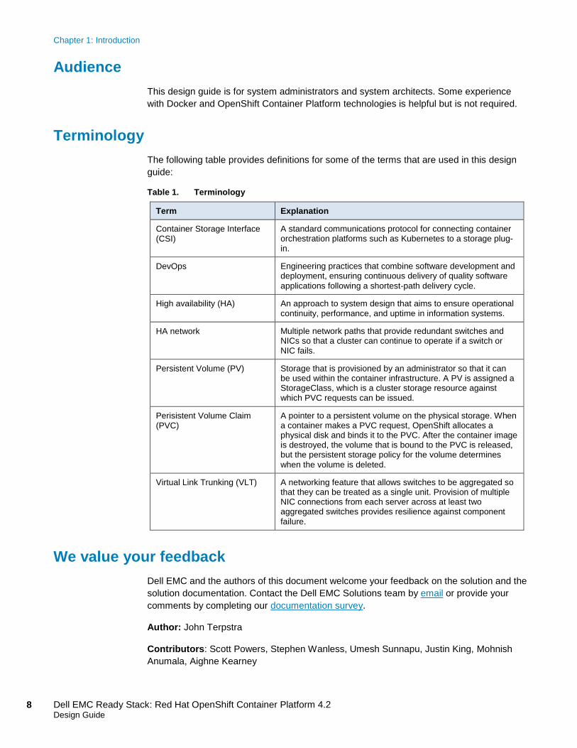
Terminology
The following table provides definitions for some of the terms that are used in this design
guide:
Table 1. Terminology
Term Explanation
Container Storage Interface (CSI)
A standard communications protocol for connecting container orchestration platforms such as Kubernetes to a storage plug-in.
DevOps Engineering practices that combine software development and deployment, ensuring continuous delivery of quality software
applications following a shortest-path delivery cycle.
High availability (HA) An approach to system design that aims to ensure operational continuity, performance, and uptime in information systems.
HA network Multiple network paths that provide redundant switches and NICs so that a cluster can continue to operate if a switch or NIC fails.
Persistent Volume (PV) Storage that is provisioned by an administrator so that it can be used within the container infrastructure. A PV is assigned a StorageClass, which is a cluster storage resource against which PVC requests can be issued.
Perisistent Volume Claim (PVC)
A pointer to a persistent volume on the physical storage. When a container makes a PVC request, OpenShift allocates a physical disk and binds it to the PVC. After the container image is destroyed, the volume that is bound to the PVC is released, but the persistent storage policy for the volume determines
when the volume is deleted.
Virtual Link Trunking (VLT) A networking feature that allows switches to be aggregated so that they can be treated as a single unit. Provision of multiple NIC connections from each server across at least two aggregated switches provides resilience against component
failure.
We value your feedback
Dell EMC and the authors of this document welcome your feedback on the solution and the
solution documentation. Contact the Dell EMC Solutions team by email or provide your
comments by completing our documentation survey.
Author: John Terpstra
Contributors: Scott Powers, Stephen Wanless, Umesh Sunnapu, Justin King, Mohnish
Anumala, Aighne Kearney

Chapter 1: Introduction
9 Dell EMC Ready Stack: Red Hat OpenShift Container Platform 4.2 Design Guide
Note: For additional information about this solution, see the Dell EMC Solutions Info Hub.

Chapter 2: Technology Overview
10 Dell EMC Ready Stack: Red Hat OpenShift Container Platform 4.2 Design Guide
Chapter 2 Technology Overview
This chapter presents the following topics:
Dell EMC on-premises hardware infrastructure ......................................... 11
Red Hat OpenShift Container Platform 4.2 ................................................. 12
Infrastructure requirements ........................................................................ 17
Software taxonomy ...................................................................................... 19

Chapter 2: Technology Overview
11 Dell EMC Ready Stack: Red Hat OpenShift Container Platform 4.2 Design Guide
Dell EMC on-premises hardware infrastructure
Dell EMC can help you define an entry-level cluster that can scale as the business grows
while you control your present capital and operating costs. We are aware that not all
container ecosystems need hundreds of servers. Customers who are new to
containerization ask for a minimum platform configuration. No single cluster size fits all
situations and circumstances. A typical entry-level production platform in the corporate and
enterprise markets has between 10 and 30 compute nodes. Large industrial-grade
container ecosystems require several full racks of servers per cluster or multiple clusters
per data center.
This solution design uses PowerEdge R640 and PowerEdge R740xd servers for compute
and storage.
PowerEdge R640 servers
The PowerEdge R640 is a general-purpose platform that supports up to 7.68 TB of
memory and twelve 2.5-in. drives and provides flexible I/O options. It is a dual-socket, 1U
platform that is ideal for dense scale-out data center computing.
The PowerEdge R640 features:
• Second-generation Intel Xeon Scalable processor product family (with up to 28 cores
and two threads per core)
• Up to six DDR4 memory channels with two DIMMs per channel per CPU and 24
DIMMs (supports DDR4 RDIMM/LRDIMM/ NVDIMM-N/DCPMM)
• PCI Express (PCIe) 3.0 enabled expansion slots (with up to 48 lanes per CPU)
PowerEdge R640 servers are preferred for the CSAH and master node roles because the
needs of these node types are easily accommodated in this 1U node configuration. Dell
EMC recognizes that customers might prefer to use identical server configurations for all
nodes in their cluster and might therefore choose Dell PowerEdge R740xd servers instead.
PowerEdge R740xd servers
Dell EMC PowerEdge R740 and R740xd are two socket, 2U rack servers designed to run
complex workloads using highly scalable memory, I/O capacity and network options. The
R740 and R740xd features the 2nd Generation Intel® Xeon® Scalable processor family, up
to 24 DIMMs, PCI Express® (PCIe) 3.0 enabled expansion slots, and a choice of network
interface technologies to cover NIC and rNDC. The PowerEdge R740 is a general-purpose
platform capable of handling demanding workloads and applications, such as data
warehouses, e-commerce, databases, and high-performance computing (HPC). The
PowerEdge R740xd adds extraordinary storage capacity options, making it well-suited for
data- intensive applications that require greater storage, while not sacrificing I/O
performance.
PowerSwitch S series switches provide the architectural agility and flexibility that are
ideal for Ready Stack for Red Hat OpenShift Container Platform 4.2.
Dell EMC
PowerEdge
servers
Dell EMC
PowerSwitch
S series
switches

Chapter 2: Technology Overview
12 Dell EMC Ready Stack: Red Hat OpenShift Container Platform 4.2 Design Guide
This Ready Stack design uses the following switches:
• Data network—PowerSwitch S5200 series open networking (ON) switches
(25/40/50/100 GbE)
• OOB management—PowerSwitch S3048-ON switch (1 GbE)
For more information about Dell EMC PowerSwitch networking technology, see Chapter 3,
Networking Infrastructure and Configuration.
Red Hat OpenShift Container Platform 4.2
OpenShift Container Platform 4.2 can host the development and run-time execution of
containerized applications, sometimes called “container workloads.” The platform uses the
Kubernetes container orchestration toolchain that is core to modern automation container
deployment, scaling, and management. OpenShift Container Platform 4.2 is designed to
meet exacting demand-driven, scale-out capabilities for workloads. We expect the software
platform to continue to mature and to expand rapidly, ensuring continued access to the
tools you need to grow your business.
OpenShift Container Platform 4.2 is supported on Red Hat Enterprise Linux 7.6 as well as
Red Hat Enterprise Linux CoreOS (RHCOS) 4.2. The OpenShift Container Platform 4.2
control plane can be deployed only on RHCOS. The control plane is hosted on master
nodes. Either RHEL 7.6 or RHCOS can be deployed on compute nodes, known as worker
nodes. Red Hat Enterprise Linux version 8 is not yet supported in OpenShift Container
Platform.
Differences between OpenShift Container Platform 3.11 and OpenShift Container Platform
4.2 include:
• Separate infrastructure nodes have been deprecated: etcd is always on the cluster
that is itself running on OpenShift Container Platform 4.2 master nodes.
• The web console has been significantly updated.
• RHCOS has replaced Atomic host.
• CRI-O is the new container run-time engine, replacing the Docker Container Engine
in OpenShift Container Platform 3.11.
• Several CLI commands have changed.
• The Quay application has been introduced as the enterprise container registry.
• CoreDNS has replaced dnsmasq.
• Operator Lifecycle Manager (OLM) has replaced the OpenShift Service Broker and
Service Catalog.
This section further describes the new features and enhancements in OpenShift Container
Platform 4.2.
Operators
OpenShift Container Platform 4.x introduced an Operator Framework to replace much of
the functionality that was previously available with Helm and Helm Charts. An operator is a
Version 4.2
compared with
version 3.11
New features
and
enhancements

Chapter 2: Technology Overview
13 Dell EMC Ready Stack: Red Hat OpenShift Container Platform 4.2 Design Guide
method by which Kubernetes-native applications are packaged and deployed into the
Kubernetes run-time environment. An operator provides a key method for management of
repetitive Kubernetes functional operations.
Operator Lifecycle Manager
The functions that OLM supports include:
• Installing, upgrading, and granting access to operators running on their cluster
• Selecting from a catalog of curated operators, with the ability to load other operators
into the cluster
• Performing rolling updates of all operators to new versions
• Implementing role-based access control (RBAC) that allows specific teams to use
specific operators
For more information, see Understanding the Operator Lifecycle Manager in the Red Hat
OpenShift documentation.
Installation and upgrade
Previously, we deployed OpenShift Container Platform 3.11 using the openshift-ansible
tool. OpenShift Container Platform 4.2 uses ignition-based deployment, a new approach to
getting your Kubernetes cluster operational quickly and simply. The ignition-based
deployment tool is called openshift-install.
The ignition-based installation method supports two modes of deployment, installer-
provisioned infrastructure and user-provisioned infrastructure.
For bare-metal deployment, which does not make use of a hypervisor, the Dell EMC Ready
Stack deployment process uses the User Provisioned Infrastructure (UPI) method. The
openshift-install tool requires very few install-time configuration settings. A post-installation
Customer Resource Definition (CRD) facility is used to specify runtime configuration
settings.
Over-the-air upgrades for asynchronous z-stream releases of OpenShift Container
Platform 4.x are available. Cluster administrators can perform an upgrade by using the
Cluster Settings tab in the web console. Updates are mirrored to the local container
registry before being pushed to the cluster.
Currently, no facility exists for performing an in-place upgrade of an OpenShift 3.11 cluster
to OpenShift 4.2. You must redeploy the cluster to use OpenShift 4.2. After deployment,
OpenShift 4.2 is capable of automatic updating, and it will likely be possible to enable
automatic upgrading to later releases. Red Hat is developing tooling to enable migration of
OpenShift 3.7 and later clusters to OpenShift 4.2. For more information, see this Red Hat
documentation.
OperatorHub
OperatorHub helps administrators discover and install optional components and
applications. It supports add-on tools and utilities from Red Hat, Red Hat partners, and the
open source community.
Chapter 2: Technology Overview
14 Dell EMC Ready Stack: Red Hat OpenShift Container Platform 4.2 Design Guide
Storage
OpenShift Container Platform 4.2 provides support for CSI 1.0, the container storage
operator, and for the manila-provisioner/operator and snapshot operator.
Red Hat has added many other capabilities to the OpenShift Container Platform to make
your container development process easier and more agile and to simplify deployment and
management operations in production. For more information, see Understanding persistent
storage in the OpenShift documentation.
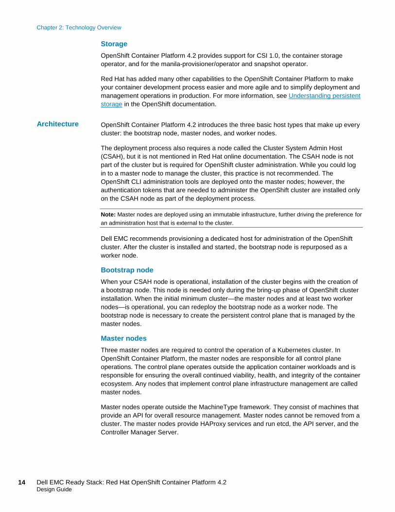
OpenShift Container Platform 4.2 introduces the three basic host types that make up every
cluster: the bootstrap node, master nodes, and worker nodes.
The deployment process also requires a node called the Cluster System Admin Host
(CSAH), but it is not mentioned in Red Hat online documentation. The CSAH node is not
part of the cluster but is required for OpenShift cluster administration. While you could log
in to a master node to manage the cluster, this practice is not recommended. The
OpenShift CLI administration tools are deployed onto the master nodes; however, the
authentication tokens that are needed to administer the OpenShift cluster are installed only
on the CSAH node as part of the deployment process.
Note: Master nodes are deployed using an immutable infrastructure, further driving the preference for
an administration host that is external to the cluster.
Dell EMC recommends provisioning a dedicated host for administration of the OpenShift
cluster. After the cluster is installed and started, the bootstrap node is repurposed as a
worker node.
Bootstrap node
When your CSAH node is operational, installation of the cluster begins with the creation of
a bootstrap node. This node is needed only during the bring-up phase of OpenShift cluster
installation. When the initial minimum cluster—the master nodes and at least two worker
nodes—is operational, you can redeploy the bootstrap node as a worker node. The
bootstrap node is necessary to create the persistent control plane that is managed by the
master nodes.
Master nodes
Three master nodes are required to control the operation of a Kubernetes cluster. In
OpenShift Container Platform, the master nodes are responsible for all control plane
operations. The control plane operates outside the application container workloads and is
responsible for ensuring the overall continued viability, health, and integrity of the container
ecosystem. Any nodes that implement control plane infrastructure management are called
master nodes.
Master nodes operate outside the MachineType framework. They consist of machines that
provide an API for overall resource management. Master nodes cannot be removed from a
cluster. The master nodes provide HAProxy services and run etcd, the API server, and the
Controller Manager Server.
Architecture

Chapter 2: Technology Overview
15 Dell EMC Ready Stack: Red Hat OpenShift Container Platform 4.2 Design Guide
Worker nodes
In an OpenShift Kubernetes-based cluster, all application containers are deployed to run
on worker nodes. Worker nodes advertise their resources and resource utilization so that
the scheduler can allocate containers and pods to worker nodes and maintain a reasonable
workload distribution. The CRI-O Kubelet service runs on each worker node. This service
receives container deployment requests and ensures that they are instantiated and put
intooperation. The Kubelet service also starts and stops container workloads. In addition,
this service manages a service proxy that handles communication between pods that are
running across worker nodes.
Logical constructs called MachineSets define worker node resources. MachineSets can be
used to match requirements for a pod to direct deployment to a matching worker node.
OpenShift Container Platform supports defining multiple machine types, each of which
defines a worker node target type. A future release of OpenShift Container Platform will
support specifically classified worker node types, such as AI hosts, infrastructure hosts,
NFV hosts, and more.
Worker nodes can be added to or deleted from a cluster as long as the viability of the
cluster is not compromised. A minimum of two viable worker nodes must be operating at all
times. Further, sufficient compute platform resources must be available to sustain the
overall cluster application container workload.
Dell EMC has simplified the process of bootstrapping your first OpenShift Container
Platform 4.2 cluster. To use the simplified process, ensure that your rack has been
provisioned with suitable network switches and servers, that network cabling has been
completed, and that Internet connectivity has been provided to the rack. Internet
connectivity is necessary for the installation of OpenShift Container Platform 4.2.
The deployment procedure begins with initial switch provisioning. This step enables
preparation and installation of the CSAH node, which includes:
• Installation of Red Hat Enterprise Linux 8
• Subscription to necessary repositories
• Creation of an Ansible user account
• Cloning of a GitHub Ansible playbook repository from the Dell ESG container
repository
• Running an Ansible playbook to initiate the installation process
Dell EMC has generated Ansible playbooks that fully prepare the CSAH node. Before
installation of the OpenShift Container Platform 4.2 cluster begins, the Ansible playbook
sets up a PXE server, DHCP server, DNS server, and HTTP server. The playbook also
creates the ignition files that you need to drive your installation of the bootstrap, master,
and worker nodes, and it configures HAProxy so that the installation infrastructure is ready
for the next step. The Ansible playbook presents a list of node types that must be deployed
in top-down order.
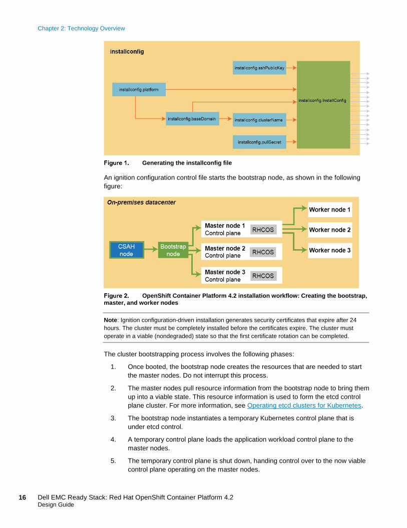
The Ansible playbook creates an installconfig file that is used to control deployment of the
bootstrap node. The following figure shows the workflow to generate the installconfig file:
Deployment
process
Chapter 2: Technology Overview
16 Dell EMC Ready Stack: Red Hat OpenShift Container Platform 4.2 Design Guide
Generating the installconfig file
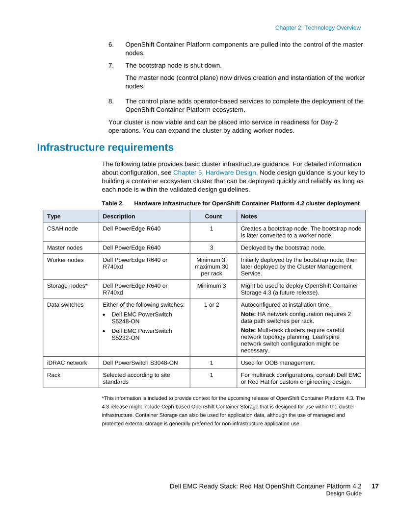
An ignition configuration control file starts the bootstrap node, as shown in the following
figure:
OpenShift Container Platform 4.2 installation workflow: Creating the bootstrap,
master, and worker nodes
Note: Ignition configuration-driven installation generates security certificates that expire after 24
hours. The cluster must be completely installed before the certificates expire. The cluster must
operate in a viable (nondegraded) state so that the first certificate rotation can be completed.
The cluster bootstrapping process involves the following phases:
1. Once booted, the bootstrap node creates the resources that are needed to start
the master nodes. Do not interrupt this process.
2. The master nodes pull resource information from the bootstrap node to bring them
up into a viable state. This resource information is used to form the etcd control
plane cluster. For more information, see Operating etcd clusters for Kubernetes.
3. The bootstrap node instantiates a temporary Kubernetes control plane that is
under etcd control.
4. A temporary control plane loads the application workload control plane to the
master nodes.
5. The temporary control plane is shut down, handing control over to the now viable
control plane operating on the master nodes.
Chapter 2: Technology Overview
17 Dell EMC Ready Stack: Red Hat OpenShift Container Platform 4.2 Design Guide
6. OpenShift Container Platform components are pulled into the control of the master
nodes.
7. The bootstrap node is shut down.
The master node (control plane) now drives creation and instantiation of the worker
nodes.
8. The control plane adds operator-based services to complete the deployment of the
OpenShift Container Platform ecosystem.
Your cluster is now viable and can be placed into service in readiness for Day-2
operations. You can expand the cluster by adding worker nodes.
Infrastructure requirements
The following table provides basic cluster infrastructure guidance. For detailed information
about configuration, see Chapter 5, Hardware Design. Node design guidance is your key to
building a container ecosystem cluster that can be deployed quickly and reliably as long as
each node is within the validated design guidelines.
Table 2. Hardware infrastructure for OpenShift Container Platform 4.2 cluster deployment
Type Description Count Notes
CSAH node Dell PowerEdge R640 1 Creates a bootstrap node. The bootstrap node is later converted to a worker node.
Master nodes Dell PowerEdge R640 3 Deployed by the bootstrap node.
Worker nodes Dell PowerEdge R640 or R740xd
Minimum 3, maximum 30
per rack
Initially deployed by the bootstrap node, then later deployed by the Cluster Management Service.
Storage nodes* Dell PowerEdge R640 or R740xd
Minimum 3 Might be used to deploy OpenShift Container Storage 4.3 (a future release).
Data switches Either of the following switches:
• Dell EMC PowerSwitch
S5248-ON
• Dell EMC PowerSwitch
S5232-ON
1 or 2 Autoconfigured at installation time.
Note: HA network configuration requires 2
data path switches per rack.
Note: Multi-rack clusters require careful network topology planning. Leaf/spine network switch configuration might be necessary.
iDRAC network Dell PowerSwitch S3048-ON 1 Used for OOB management.
Rack Selected according to site standards
1 For multirack configurations, consult Dell EMC or Red Hat for custom engineering design.
*This information is included to provide context for the upcoming release of OpenShift Container Platform 4.3. The
4.3 release might include Ceph-based OpenShift Container Storage that is designed for use within the cluster
infrastructure. Container Storage can also be used for application data, although the use of managed and
protected external storage is generally preferred for non-infrastructure application use.
Chapter 2: Technology Overview
18 Dell EMC Ready Stack: Red Hat OpenShift Container Platform 4.2 Design Guide
Installing OpenShift Container Platform requires, at a minimum, the following nodes:
• One CSAH node, which is used to install the bootstrap node. The CSAH node is
used later to manage the cluster while it is in production use.
• One bootstrap machine, which is used to deploy the OpenShift Container Platform
cluster on the three master nodes. You can remove the bootstrap node after the
cluster is installed.
• Three control plane (or master) nodes.
• At least two compute (or worker) nodes.
Note: Dell EMC Ready Stack for Red Hat OpenShift Container Platform 4.2 does not currently
support redundant network configuration because of technical issues that we discovered during our
development work. These issues will likely be resolved by the time Red Hat releases Open Shift
Container Platform 4.3. We therefore recommend that all servers are provisioned with dual network
adapters at a minimum.
The HA of key services that make up your cluster is necessary to ensure run-time integrity.
The use of separate physical nodes for each cluster node type is foundational to the design
guidance that is provided for your bare-metal cluster. As used in this guide, HA includes
the provisioning of at least dual network adapters and dual network switches that are
configured to provide redundant pathing. The redundant pathing provides for network
continuity if a network adapter or a network switch fails.
OpenShift Container Platform 4.2 is supported on Red Hat Enterprise Linux 7.6 and later,
as well as on Red Hat Enterprise Linux CoreOS 4.1. You must use Red Hat Enterprise
Linux CoreOS (RHCOS) for the control plane (or master) machines and can use either
RHCOS or Red Hat Enterprise Linux 7.6 for compute (or worker) machines. The bootstrap
and master nodes must use RHCOS as their operating system. Each of these nodes must
be immutable.
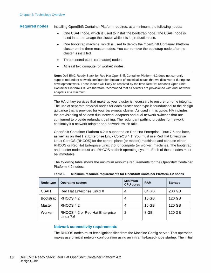
The following table shows the minimum resource requirements for the OpenShift Container
Platform 4.2 nodes:
Table 3. Minimum resource requirements for OpenShift Container Platform 4.2 nodes
Node type Operating system Minimum CPU cores
RAM Storage
CSAH Red Hat Enterprise Linux 8 4 64 GB 200 GB
Bootstrap RHCOS 4.2 4 16 GB 120 GB
Master RHCOS 4.2 4 16 GB 120 GB
Worker RHCOS 4.2 or Red Hat Enterprise Linux 7.6
2 8 GB 120 GB
Network connectivity requirements
The RHCOS nodes must fetch ignition files from the Machine Config server. This operation
makes use of initial network configuration using an initramfs-based-node startup. The initial
Required nodes

Chapter 2: Technology Overview
19 Dell EMC Ready Stack: Red Hat OpenShift Container Platform 4.2 Design Guide
boot requires a DHCP server to provide a network connection to give access to the ignition
files for that node. Static IP addresses can be assigned for subsequent operations.
Software taxonomy
By default, the cluster operator pods are distributed across master and worker nodes. The
openshift-kube-scheduler-operator is deployed to run on master (etcd) nodes. The control
plane (master node) determines placement of all additional pods across the cluster, based
on the predefined policies. Most of the cluster core components, such as the API server,
authentication, controller-manager, scheduler, and so on, are deployed to run on master
nodes. All cluster operators for OpenShift pods run on master nodes.
Applications that are manually created after an OpenShift Container Platform 4.2
deployment run on worker nodes. The OpenShift scheduler allocates application pods
automatically. However, you can deploy some of the cluster pods to run across all (master
and worker) nodes, for example, monitoring pods (node-exporter), cluster tuning, Multus,
SDN, and so on. The following table shows the default deployment of the base system:
Table 4. Default deployment of OpenShift base system component pods
Master nodes Worker nodes
Apiserver authentication cluster-node-tuning
cloud-credential cluster-node-tuning machine-config
cluster-samples cluster-storage certified-operators
cluster-version console community-operators
controller-manager cluster-image-registry redhat-operators
Dns ingress
Insights kube-apiserver
kube-controller-manager kube-scheduler
cluster-autoscaler machine-api
machine-config redhat
cluster-monitoring prometheus
network catalog
olm services-ca
service-catalog-apiserver service-catalog-manager
etcd-quorum

Chapter 3: Networking Infrastructure and Configuration
20 Dell EMC Ready Stack: Red Hat OpenShift Container Platform 4.2 Design Guide
Chapter 3 Networking Infrastructure and Configuration
This chapter presents the following topics:
Overview…… ................................................................................................ 21
OpenShift network operations .................................................................... 23
Multinetwork support ................................................................................... 26
Physical network configuration .................................................................. 27
Network design ............................................................................................ 30

Chapter 3: Networking Infrastructure and Configuration
21 Dell EMC Ready Stack: Red Hat OpenShift Container Platform 4.2 Design Guide
Overview
A Dell EMC Ready Stack for Red Hat OpenShift Container Platform 4.2 deployment
consists of a minimum of seven physical nodes, which are the host servers that form an
integral part of a Kubernetes container ecosystem. The container ecosystem consists of
many components and operations, each of which require network connectivity and the
ability to communicate with one another and respond to incoming network requests.
Ready Stack for Red Hat OpenShift Container Platform 4.2 uses Dell EMC PowerSwitch
networking infrastructure. You can replace the PowerSwitch network communications
infrastructure with third-party network switches, but you will not be able to use the Dell
EMC automated switch-provisioning process; instead, you must manage the provisioning
process outside of the deployment processes that this design guide describes.
The new Dell EMC data center networking model is an open ecosystem in which
organizations can choose network switches from a range of innovative, industry-standard
network applications, network operating systems, and network hardware. Open networking
solutions enable IT managers to build an application-agnostic infrastructure and to simplify
data center management with standard automation tools and standards-based open
platforms.
Dell EMC has rebranded the Open Networking Z series, S series, and N series switch
portfolio to Dell EMC PowerSwitch.
Dell EMC PowerSwitch networking provides:
• Disaggregated-hardware/software switching solutions
• Support for Open Network Install Environment (ONIE), enabling zero-touch
installation of alternate network operating systems
• Your choice of network operating system to help simplify data-center fabric
orchestration and automation
• A broad ecosystem of applications and tools, both open-source and Linux-based,
providing more options to optimize and manage your network
Dell EMC PowerSwitch solutions are cost-effective and easy to deploy, providing a clear
path to software-defined networking (SDN). The following figure depicts Dell EMC’s open
networking model:
Dell EMC
network
environment
Dell EMC
PowerSwitch
family

Chapter 3: Networking Infrastructure and Configuration
22 Dell EMC Ready Stack: Red Hat OpenShift Container Platform 4.2 Design Guide
Open networking design
Dell EMC Networking OS10 Enterprise Edition is a network operating system supporting
multiple architectures and environments, as shown in the following figure:
OS10 software model
The OS10 solution allows multilayered disaggregation of network functions that are layered
on an open-source Linux-based operating system. OS10 contributions to open source
provide users with the freedom and flexibility to pick their own third-party networking,
monitoring, management, and orchestration applications. OS10 Enterprise Edition bundles
an industry-hardened networking stack featuring standard L2 and L3 protocols over
established northbound interfaces such as CLI, SNMP, and REST. The Switch Abstraction
Interface (SAI) and Control Plane Services (CPS) abstraction layers provide disaggregation
at the Network Processing Unit (NPU) and for the software applications that are written on
top of the Linux kernel.
The IT industry has frequently highlighted the challenges of bootstrapping a new cluster
infrastructure, especially the challenges that are inherent in initial cluster data plane
network provisioning during the cluster deployment process.
OS10 network
operating
system
Deployment
automation
Chapter 3: Networking Infrastructure and Configuration
23 Dell EMC Ready Stack: Red Hat OpenShift Container Platform 4.2 Design Guide
Dell EMC PowerSwitch networking devices running OS10 provide a consistent switch
network operating environment that makes it possible to automate initial switch
provisioning, easing the way for the deployment of your OpenShift Container Platform
software infrastructure. For more information, see the Dell EMC Ready Stack: Red Hat
OpenShift Container Platform 4.2 Deployment Guide.
OpenShift network operations
OpenShift Container Platform 4.2 includes an operator-driven framework that manages the
network infrastructure, the CNI. The CNI interface provides a choice of CNI plug-ins that
you can deploy to enable various types of communication channels. The CNI interface is
also used to enable access to SmartNICs and to add-in adapters and devices such as
GPUs and FPGAs.
Servers (nodes) and container entities that are deployed within the Kubernetes cluster
operate from within a pod.
Applications are run on “worker” (compute) nodes. Each worker node is equipped with
resources such as CPU cores, memory, storage, NICs, and add-in host adapters (GPUs,
SmartNICs, FPGAs, and so on). Kubernetes provides a mechanism to enable add-in
resources such as NICs, GPUs, and FPGAs—the Container Network Interface (CNI) API.
The CNI API uses the Multus CNI plug-in to enable attachment of multiple adapter
interfaces on each pod. Container Resource Definitions (CRD) objects handle the
configuration of Multus CNI plug-ins.
Kubernetes master nodes host the cluster-wide control plane infrastructure that includes:
• The etcd utility that manages and distributes the cluster registry (a database that
stores cluster state information) and forms the central knowledge base that is used
to maintain cluster consistency
• Controller Manager
• Scheduler
• Kubectl instances
A pod, a basic unit of application deployment, consists of one or more containers that are
deployed together on the same worker node. A pod shares the worker node network
infrastructure with the other network resources that make up the cluster. As service
demand expands, more identical pods are often deployed to the same or other worker
nodes.
Networking is critical to the operation of a Kubernetes cluster. Your container ecosystem
ceases to exist without networking. Four basic network communication flows arise within
every Kubernetes cluster:
• Container-to-container connections (also called highly coupled communication)
• Pods communication over the localhost network (127.0.0.1)
• Pod-to-pod connections, as described in this design guide
Kubernetes
components
Operating
components
Container
communications
Chapter 3: Networking Infrastructure and Configuration
24 Dell EMC Ready Stack: Red Hat OpenShift Container Platform 4.2 Design Guide
• Pod-to-service and ingress-to-service connections, which are handled by services
Pods share the Linux kernel namespaces, cgroups, and Linux operating system process
isolation methods. Pods can communicate over standard IPC methods such as
semaphores or shared memory. Containers that communicate within their pod use the
localhost network address. Containers that communicate with any external pod originate
their traffic based on the IP address of the pod.
Application containers make use of shared storage volumes (generally configured as part
of the pod resource) that are mounted as part of the shared storage for each pod. Pods
generally make use of ephemeral storage so that when the pod expires its storage is
released and any storage it used is considered lost. Storage that is assigned to a pod is
shared with all the containers that operate within it. In other words, a pod and its containers
share the same shared part of the host file system. A pod can also be configured to use
persistent storage volumes, which are also shared by all containers within a pod. Persistent
volumes permit application storage to continue across container restarts.
Network traffic that might be associated with nonlocal storage must be able to route across
node network infrastructure.
Services are generally used to abstract access to Kubernetes pods. Every node in a
Kubernetes cluster runs a kube-proxy and is responsible for implementing virtual IP (VIP)
for service.
Kubernetes supports two primary modes of finding (or resolving) a service:
• Using environment variables—This method requires a reboot of the pods when the
IP address of the service changes.
• Using DNS—OpenShift Container Platform 4.2 uses CoreDNS to resolve service IP
addresses.
Some part of your application (for example, front ends) might want to expose a service
outside the application. If the service uses HTTP/HTTPS or any other TLS-encrypted
protocol, use an ingress controller. Otherwise, use a load balancer, external IP address, or
a node port. A node port exposes the service on a static port on the node IP address. A
service with NodePort-type as a resource exposes it on a specific port on all nodes in the
cluster. Ensure that the external IP addresses are routed to the nodes.
The OpenShift Container Platform uses an ingress controller to provide external access.
The ingress controller generally runs on two worker nodes but can be scaled up as
required.
Dell EMC recommends creating a wildcard DNS entry and then setting up an ingress
controller. This method enables you to work only within the context of an ingress controller.
An ingress controller accepts external requests and then proxies them based on the routes
that are provisioned.
A service is exposed by creating a route and using the ClusterIP. Routes are created in the
OpenShift Container Platform project and a set of routes are admitted into ingress
controllers.
Services
networking
Ingress
controller
Chapter 3: Networking Infrastructure and Configuration
25 Dell EMC Ready Stack: Red Hat OpenShift Container Platform 4.2 Design Guide
Sharing ingress controllers enables you to:
• Load balance the incoming traffic.
• Segregate the required traffic to a single ingress controller.
Sharing can be performed on route labels or name spaces.
In addition to the Operator Framework, three main operators are available for network
administration:
• Cluster Network Operator (CNO)—Deploys the OpenShift SDN plug-in during
cluster installation and manages kube-proxy running on each node
• DNS Operator—Deploys and manages CoreDNS and instructs pods to use the
CoreDNS IP address for name resolution
• Ingress Operator—Enables external access to OpenShift Cluster Platform cluster
services and deploys and manages one or more HAProxy-based ingress controllers
to handle routing
OpenShift SDN creates an overlay network based on Open Virtual Switch (OVS), which
enables communication between pods across the OpenShift Container Platform cluster.
OVS operates in one of the following modes:
• Network policy mode (the default), which allows custom isolation policies
• Multitenant mode, which provides project-level isolation for pods and services
• Subnet mode, which provides a flat network
OpenShift Container Platform 4.2 supports additional SDN orchestration and management
plug-ins that comply with the CNI specification. See Chapter 6, Use Cases, for examples
of use cases for CNI plug-ins.
A number of distributed microservices work together to make up an application. OpenShift
Service Mesh connects these distributed microservices over the networks within the
cluster, and potentially across multiple clusters. The Service Mesh implementation is based
on Istio, an open source project.
OpenShift Service Mesh provides a uniform way to connect, manage, and observe
microservices-based applications. It is installed automatically using operators from the
OperatorHub. Service Mesh uses code from the following open source project operators:
• ElasticSearch
• Jaeger
• Kiali
Service Mesh has key functional components that belong to either the data plane or the
control plane:
• Envoy proxy, which is deployed as a sidecar, intercepts all traffic for all services in
the Service Mesh.
Networking
operators
OpenShift SDN
Service Mesh
Chapter 3: Networking Infrastructure and Configuration
26 Dell EMC Ready Stack: Red Hat OpenShift Container Platform 4.2 Design Guide
• Mixer enforces access control and collects telemetry data.
• Pilot provides service discovery for the envoy sidecars.
• Citadel provides strong service-to-service and end-user authentication with built-in
identity and credential management.
Service Mesh controls traffic flows between microservices, enforces access policies, and
aggregates telemetry data. It provides a policy-driven set of controls over network
pathways that are provided by SDN- and CNI.
Users define the granularity of Service Mesh deployment, enabling them to meet their
specific deployment and application needs. Service Mesh can be employed at the cluster
level or at the project level.
Monitoring and troubleshooting the OpenShift Container Platform 4.2 cluster are important
tasks. The cluster administrator can:
• Use Kiali to monitor the Service Mesh. Kiali requires Prometheus, which stores the
metrics data.
• Use Jaeger to conduct end-to-end tracing of a microservices-based application for
troubleshooting and to understand performance implications.
Multinetwork support
OpenShift Container Platform 4.2 introduces a powerful feature—support for multiple
networks pods. OpenShift Container Platform 4.2 comes with a default network. You can
define additional networks using the Multus CNI plug-in and then chain the plug-ins. These
additional networks are useful for increasing the networking capacity requirement of the
pods and when traffic separation requirements arise because of security concerns or
network routing requirements.
The following CNI plug-ins are available for creating additional networks in OpenShift
Container Platform 4.2:
• Bridge—The same host pods can communicate over a bridge-based additional
network.
• Host-device—Pods can access the host’s physical Ethernet network device.
• Macvlan—Pods attached to a macvlan-based additional network have a unique
MAC address and communicate using a physical network interface.
• Ipvlan—Pods communicate over an ipvlan-based additional network.
• SR-IOV—Pods can attach to a virtual function (VF) interface. (This is a Technology
Preview feature only.)
When pods are provisioned with additional network interfaces based on macvlan or ipvlan,
corresponding leaf switch ports must match the VLAN configuration of the host. A matching
failure results in the loss of traffic.
Leaf switch
consideration
Chapter 3: Networking Infrastructure and Configuration
27 Dell EMC Ready Stack: Red Hat OpenShift Container Platform 4.2 Design Guide
Physical network configuration
Dell EMC servers offer many network adapter options. In the simplified deployment, each
server in the rack is connected to:
• A leaf switch with a single network interface of choice (10/25/100 GbE)
• A management switch (typically 1 GbE) for iDRAC connectivity
Leaf switches are connected to spine switches in a resilient manner.
Dell EMC PowerSwitch S5248F-ON
Each S5248F-ON switch provides six 100 GbE uplink ports. The ports enable high-speed
connectivity to spine switches or directly to the data center core network infrastructure.
They can also be used to extend connectivity to other racks.
The remaining 48 ports of 25 GbE are used for server connectivity. An OpenShift Container
Platform cluster with up to 48 server nodes can easily be accommodated using a pair of
S5248F-ON switches. Expansion of an OpenShift Container Platform single-rack cluster
beyond 48 nodes is managed in one of two ways: add a second S5248F-ON switch or use
the S5232F-ON switch.
Dell EMC PowerSwitch S5232F-ON
The S5232F-ON switch also supports ONIE for zero-touch installation of network operating
systems. In addition to its use in 100 GbE leaf-spine deployments, the S5232F-ON switch
can be used in high-density deployments, using breakout cables, to achieve up to 128 x 10
GbE or 128 x 25 GbE ports.
The network architecture employs a VLT connection between the two top-of-rack (ToR)
switches. In a non-VLT environment, redundancy requires idle equipment, which drives up
infrastructure costs and increases risks. In a VLT environment, all paths are active, adding
immediate value and throughput while still protecting against hardware failures.
VLT technology allows a server or bridge to uplink a physical trunk into more than one Dell
PowerSwitch switch by treating the uplink as one logical trunk. A VLT-connected pair of
switches acts as a single switch to a connecting bridge or server. Both links from the bridge
network can actively forward and receive traffic. VLT provides a replacement for Spanning
Tree Protocol (STP)-based networks by providing both redundancy and full bandwidth
utilization using multiple active paths.
The major benefits of VLT technology are:
• Dual control plane for highly available, resilient network services
• Full utilization of the active link aggregation (LAG) interfaces
• Active-active design for seamless operations during maintenance events
The VLTi configuration in this architecture uses two 100 GbE ports from each ToR switch.
You can also use 100 GbE ports for high-speed connectivity to spine switches or directly to
the data center core network infrastructure. You can also use them to extend connectivity
to other racks.
Single-rack
networking
Resilient
networking
Chapter 3: Networking Infrastructure and Configuration
28 Dell EMC Ready Stack: Red Hat OpenShift Container Platform 4.2 Design Guide
You can scale container solutions by adding multiple application and storage nodes. Your
solution might contain multiple racks of servers. To create a nonblocking fabric to meet the
needs of the microservices data traffic, we used a leaf-spine network.
Leaf-spine overview
The following concepts apply to Layer 2 and Layer 3 leaf-spine topologies:
• Each leaf switch connects to every spine switch in the topology.
• Servers, storage arrays, edge routers, and similar devices always connect to leaf
switches, but never to spines.
We used a single leaf switch at the top of each rack. We employed VLT in the spine layer,
which allows all connections to be active while also providing fault tolerance. As
administrators add racks to the data center, leaf switches are added to each new rack.
The total number of leaf-spine connections is equal to the number of leaf switches
multiplied by the number of spine switches. You can increase the bandwidth of the fabric
by adding connections between leaves and spines if the spine layer has capacity for the
additional connections.
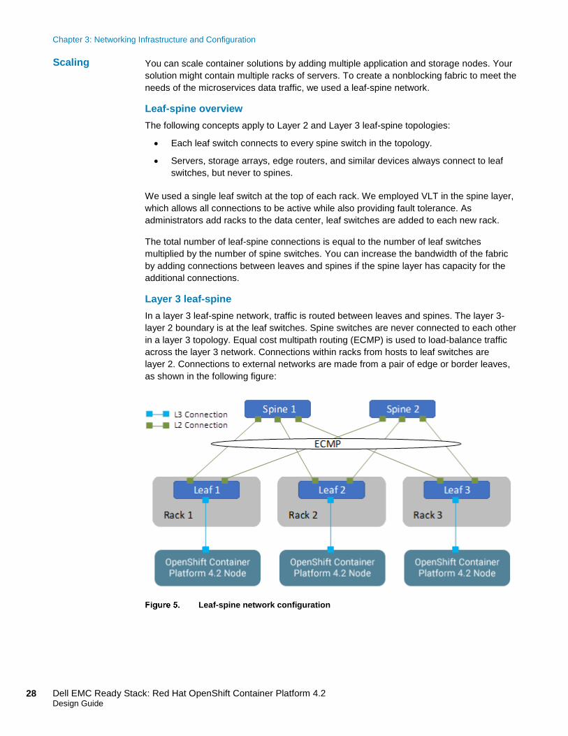
Layer 3 leaf-spine
In a layer 3 leaf-spine network, traffic is routed between leaves and spines. The layer 3-
layer 2 boundary is at the leaf switches. Spine switches are never connected to each other
in a layer 3 topology. Equal cost multipath routing (ECMP) is used to load-balance traffic
across the layer 3 network. Connections within racks from hosts to leaf switches are
layer 2. Connections to external networks are made from a pair of edge or border leaves,
as shown in the following figure:
Leaf-spine network configuration
Scaling

Chapter 3: Networking Infrastructure and Configuration
29 Dell EMC Ready Stack: Red Hat OpenShift Container Platform 4.2 Design Guide
Networking limitation
In our development work, we were unable to deploy bonded multi-NIC configuration of
cluster nodes. Two methods can be used to deploy multiple NICs on a cluster node: one
method makes use of the ignition control file, and the other requires passing kernel
parameters to the Linux kernel that boots each node. Editing the ignition control file is
beyond the scope of an automated deployment currently. When we added the NIC bonding
parameters to the kernel command line, the nodes entered a continuous boot cycle. To
address the difficulties, we used a single leaf switch at the top of each rack. Dell EMC
recognizes the importance of bonded multi-NIC support for HA in the network
infrastructure. With HA network configuration, each rack has a pair of switches configured
with VLTi at the leaf level.
This section describes how to configure the PowerSwitch switches that are used for an
OpenShift deployment at various scales.
Configuring VLT
The VLT configuration involves the following high-level steps:
1. Enable Spanning Tree on the VLT peer switches. Spanning Tree is enabled by
default and is recommended to prevent loops in a VLT domain. RPVST+ (the
default) and RSTP modes are supported on VLT ports.
2. Create a VLT domain and configure the VLT interconnect (VLTi).
3. Configure the VLT Priority, VLT MAC Address, and VLT Backup Link.
4. Configure the LAG for the connected device.
5. Verify and monitor the status of VLT and mismatches by using appropriate OS10
show commands.
Installation with Ansible
Dell EMC Networking modules are supported in Ansible core from Ansible 2.3. You can
use these modules to manage and automate Dell EMC switches running OS10. The
modules are currently run in local connection mode, using CLI and SSH transport.
For an example of Clos fabric deployment based on Border Gateway Protocol (BGP), see
Provision CLOS fabric using Dell EMC Networking Ansible modules example.
Configuring
Dell EMC
PowerSwitch
switches

Chapter 3: Networking Infrastructure and Configuration
30 Dell EMC Ready Stack: Red Hat OpenShift Container Platform 4.2 Design Guide
Network design
Dell EMC networking products are designed for ease of use and to enable resilient network
creation. OpenShift Container Platform 4.2 introduces various advanced networking features to
enable containers for high performance and monitoring. Our recommended design follows
these principles:
• Meet network capacity and the segregation requirements of the container pod.
• Provide the ability to monitor and trace container communications.
• Configure dual-homing of the OpenShift Container Platform node to two VLT switches.
• Create a scalable and resilient network fabric to increase cluster size.
Container network capacity and segregation
Container networking takes advantage of the high speed (25/100 GbE) network interfaces of
the Dell EMC server portfolio. In addition, to meet network capacity requirements, you can use
available CNI plug-ins to attach more networks to pods.
Additional networks are useful when network traffic isolation is required. Networking
applications such as Container Network Functions (CNFs) have control traffic and data traffic.
These different traffic types have different processing, security, and performance requirements.
Pods can be attached to the SR-IOV virtual function (VF) interface on the host system for traffic
isolation and to increase I/O performance.
Monitoring and tracing
OpenShift Container Platform 4.2 introduced the Red Hat OpenShift Service Mesh. Users can
monitor container traffic using Kiali and perform end-to-end tracing of applications using Jaeger.
Dual-homing
Dual-homing means that each node that makes up the OpenShift cluster has at least two
NICs, each connected to at least two switches. The switches require VLT connections so
that together they operate as a single unit of connectivity to provide a redundant data path
for all network traffic. The NICs at each node and the ports they connect to on each of the
switches can make use of link aggregation bonding to assure HA operation.
Note: Dual-homing deployment is not currently possible with OpenShift Container Platform 4.2. It is
likely that dual-homing will be enabled with the OpenShift Container Platform 4.3 release and we
therefore recommend having the infrastructure in place to support it.
Network fabric
A nonblocking fabric is required to meet the needs of the microservices data traffic. Dell
EMC recommends deploying a leaf-spine network.
Essential
guidelines
Chapter 4: Storage Overview
31 Dell EMC Ready Stack: Red Hat OpenShift Container Platform 4.2 Design Guide
Chapter 4 Storage Overview
This chapter presents the following topics:
CSI storage… .............................................................................................. 32
CSI and persistent storage ......................................................................... 33
Dell EMC supported storage products ...................................................... 34

Chapter 4: Storage Overview
32 Dell EMC Ready Stack: Red Hat OpenShift Container Platform 4.2 Design Guide
CSI storage
OpenShift Container Platform 4.2 introduces support for the CSI operator-framework-driven
API. This CSI API manages the control plane (that is, it runs on the master nodes) to
orchestrate and manage configuration and tear-down of data-path storage operations.
Storage driver plug-in support was available in earlier Kubernetes releases but required
volume plug-ins to be built into the core Kubernetes code base. Kubernetes version 1.14
and CSI API version 1.0 are built into OpenShift Container Platform 4.2.
Prior to release of the CSI API support, volume plug-ins were distributed with the
Kubernetes code. Known as “in-tree” storage drivers, each plug-in consisted of two parts: a
data plane storage connector and an orchestration component that managed storage
volumes. CSI enables container volume storage drivers to be provided from outside the
Kubernetes code base (“out-of-tree” storage drivers). The benefit for storage vendors is
that they can provide extended storage support without the need to distribute the drivers
with Kubernetes. CSI drivers can deploy the storage plug-in (on worker nodes) and an
operator that is called by the Kubernetes control plane infrastructure (on master nodes).
The following figure shows a comparison of in-tree and out-of-tree CSI drivers:
Comparison of In-tree and out-of-tree CSI drivers
A Kubernetes container infrastructure operates best with shared distributed storage. The
container ecosystem has internal storage needs. Application pods require storage that can
be used from the host worker node local disk storage or from a shared distributed storage
pool. Applications might also require additional storage that is external to the cluster. The
software application developer has many options from which to choose and can take
guidance from industry best practices or published documents from trusted sources.
The upcoming 4.3 release of OpenShift Container Platform is expected to include Ceph-
based OpenShift Container Storage 4.3, a means of providing integrated distributed
storage for your container platform infrastructure using the new CSI drivers.

Chapter 4: Storage Overview
33 Dell EMC Ready Stack: Red Hat OpenShift Container Platform 4.2 Design Guide
CSI and persistent storage
All storage within OpenShift Container Platform 4.x is managed separately from compute
(worker node) resources and from all networking and connectivity infrastructure facilities.
The introduction of the CSI API is designed to abstract storage use and to enable storage
portability.
The CSI facility adds new storage capabilities to the Kubernetes container platform. CSI
enables the deployment of new storage types without the need for changes to Kubernetes
platform code.
The CSI API introduces two new resources: PersistentVolume (PV) and
PersistentVolumeClaim (PVC) objects. In addition, the Storage Classes or StatefulSet
concepts describe the types of storage that might be provisioned for container use within a
container platform.
These resources represent logical constructs that are used within the Kubernetes container
infrastructure to maintain storage for all the container ecosystem components that depend
on storage. Developers and operators can deploy applications without having specific
technical knowledge of the underlying storage technology.
The OpenShift Container Platform administrator is responsible for provisioning targeted
storage PVs, making them available for container platform use. PVs are unrelated to pods
and pod storage life cycles. PVs are internal objects against which PVCs are created.
All pods are deployed as part of a project. PVCs are specific to a project. PVCs enable use
of preferred storage types that are either integrated into the OpenShift Container Platform
or located in external storage (sometimes referred to as pre-existing storage).
Storage using PVCs is consumed or used in two ways: statically or dynamically. Static
storage can be attached to one or more pods by static assignment of a PV to a PVC and
then to a specific pod or pods.
After a PV is bound to a PVC, the PV cannot be bound to another PVC. This restriction
effectively binds the PV to a single namespace, that of the binding project. A PV that has
been created for dynamic use is a storage class object that functions as, and consumed
automatically as, a cluster resource.
OpenShift Container Platform natively supports the following PV types:
• AWS Elastic Block Store (EBS)
• Azure Disk
• Azure File
• Fibre Channel (FC) (can only be assigned and attached to a node)
• GCE Persistent Disk
• HostPath (local disk)
• iSCSI (generic)
• NFS (generic)
PV types

Chapter 4: Storage Overview
34 Dell EMC Ready Stack: Red Hat OpenShift Container Platform 4.2 Design Guide
• VMware vSphere
The CSI API extends the storage types that can be used within an OpenShift container
platform.
Each PV has predetermined storage capacity that is set in its capacity definition
parameter. The storage capacity can be set or requested by a pod that is launched within
the container platform. Expect the choice of control parameters to expand as the CSI API is
extended and as it matures.
A resource provider can determine how the PV is created and can set the storage control
parameters. Access mode support is specific to the type of storage volume that is
provisioned as a PV. Provider capabilities determine the PV’s access modes, while the
capabilities of each PV determine the modes that are supported by that particular volume.
For example, NFS can support multiple read-write clients, but a specific NFS PV might be
configured as read-only.
Pod claims are matched to volumes with compatible access modes based on two matching
criteria: access modes and size. A pod claim’s access modes represent a request.
Dell EMC supported storage products
The following table provides an overview of Dell EMC storage products that have pending
CSI driver support:
Table 5. Dell EMC storage and supported access modes for PVs
The validation work that is documented in this guide was performed using Dell EMC Unity
based NFS storage without use of the CSI drivers. The CSI storage drivers for Dell EMC
Unity, PowerMax, VxFlexOS, and Isilon are being developed and validated currently.
PV capacity
PV access
modes
Volume plug-in ReadWriteOnce ReadOnlyMany ReadWriteMany
Dell EMC Unity (iSCSI) ✅ ✅ —
Dell EMC Unity (FC) ✅ ✅ —
Dell EMC Unity NFS ✅ ✅ ✅
Dell EMC PowerMax (FC) ✅ ✅ —
Dell EMC PowerMax (iSCSI)
✅ ✅ —
HostPath (local disk) ✅ — —
iSCSI (generic) ✅ ✅ —
NFS (generic) ✅ ✅ ✅
VMware vSphere/VSAN ✅ — —
Chapter 5: Hardware Design
35 Dell EMC Ready Stack: Red Hat OpenShift Container Platform 4.2 Design Guide
Chapter 5 Hardware Design
This chapter presents the following topics:
Introduction to hardware design ...................................................................... 36
Hardware acquisition planning ........................................................................ 38
Validated hardware configuration options ...................................................... 41

Chapter 5: Hardware Design
36 Dell EMC Ready Stack: Red Hat OpenShift Container Platform 4.2 Design Guide
Introduction to hardware design
This chapter describes node design options that enable you to build a cluster for a wide
range of workload-handling capabilities, expanding on information that was introduced in
Chapter 2, Technology Overview. In most cases, the platform design process ensures that
your cluster can meet initial workloads. The cluster must also be capable of being scaled
out as the demand for workload handling grows.
Specifying and building an on-premises Kubernetes cluster without guidance is a daunting
task. Building that same cluster into a resilient, development-ready or production-ready
container ecosystem can be challenging. Dell EMC Ready Stack for Red Hat OpenShift
Container Platform 4.2 provides an easy way to erect and commission a Kubernetes
cluster. However, if you want to match the design and capacity of your platform
infrastructure to specific site needs, additional tasks are required.
Organizations that have successfully built and deployed on-premises container ecosystems
understand their current container infrastructure and can usually best determine the initial
configuration needs for their next venture into container operations. With this knowledge, it
is easier to approach CPU sizing, memory configuration, network bandwidth capacity
specification, and storage needs.
In the absence of a clear understanding of your workload and the resources you need, the
following design information might help to explain the physical hardware requirements.
Calculations from measured or assumed requirements are only a guide to real-world
operational requirements. Many operational factors can impact how the complexity of a
container ecosystem affects operational latencies. A good practice is to add a safety
margin to all physical resource estimates. Dell EMC’s goal in providing this information is to
help you get Day-2 operations underway as smoothly as possible.
Kubernetes and the platforms into which it is integrated have design-limited resource
utilization capabilities. The following sections describe limits for Kubernetes 1.14 (the
version that is used in OpenShift Container Platform 4.2) and the published limits for
OpenShift Container Platform 4.2. These limits set the outer boundaries for node design for
your container ecosystem.
Application pods (software) that run on a cluster can be scaled up until available physical
cluster resources (CPU cores, memory, network bandwidth I/O, and storage I/O) are
reached. Physical cluster resources can be oversubscribed in production use.
Oversubscription affects the service-level performance of all application pods that are
running on a node or across a cluster.
When work began on development of OpenShift Container Platform 4.2, the available
Kubernetes release was version 1.14. The Kubernetes website lists the following cluster
limits:
• Nodes per cluster: 5,000
• Pods per cluster: 150,000
• Containers per cluster: 300,000
• Pods per node: 100
Kubernetes
limits
Chapter 5: Hardware Design
37 Dell EMC Ready Stack: Red Hat OpenShift Container Platform 4.2 Design Guide
The design and architecture of Kubernetes places resource hosting limits on a Kubernetes
cluster. Red Hat offers support for OpenShift Container Platform 4.2 up to these limits, as
described in Planning your environment according to object limits:
• Nodes per cluster: 2,000
• Pods per cluster: 150,000
• Pods per node: 250
• Pods per core: Not specified; limited by maximum pods per node
• Namespaces per cluster: 10,000
• Services per cluster: 10,000
• Pods per namespace: 25,000
• Services per namespace: 5,000
• Back ends per service: 5,000
• Deployments per namespace: 2,000
Use this information when you design your container ecosystem.
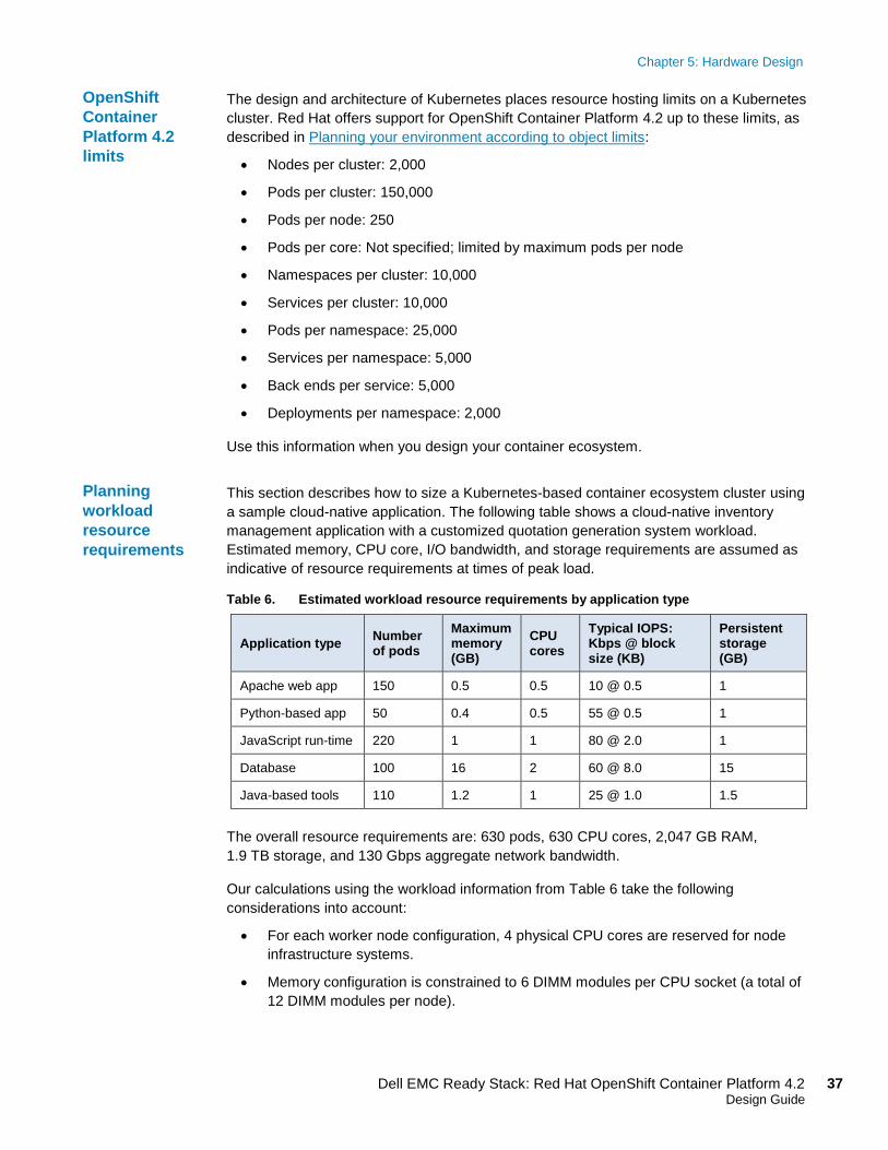
This section describes how to size a Kubernetes-based container ecosystem cluster using
a sample cloud-native application. The following table shows a cloud-native inventory
management application with a customized quotation generation system workload.
Estimated memory, CPU core, I/O bandwidth, and storage requirements are assumed as
indicative of resource requirements at times of peak load.
Table 6. Estimated workload resource requirements by application type
Application type Number of pods
Maximum memory (GB)
CPU cores
Typical IOPS: Kbps @ block size (KB)
Persistent storage (GB)
Apache web app 150 0.5 0.5 10 @ 0.5 1
Python-based app 50 0.4 0.5 55 @ 0.5 1
JavaScript run-time 220 1 1 80 @ 2.0 1
Database 100 16 2 60 @ 8.0 15
Java-based tools 110 1.2 1 25 @ 1.0 1.5
The overall resource requirements are: 630 pods, 630 CPU cores, 2,047 GB RAM,
1.9 TB storage, and 130 Gbps aggregate network bandwidth.
Our calculations using the workload information from Table 6 take the following
considerations into account:
• For each worker node configuration, 4 physical CPU cores are reserved for node
infrastructure systems.
• Memory configuration is constrained to 6 DIMM modules per CPU socket (a total of
12 DIMM modules per node).
OpenShift
Container
Platform 4.2
limits
Planning
workload
resource
requirements

Chapter 5: Hardware Design
38 Dell EMC Ready Stack: Red Hat OpenShift Container Platform 4.2 Design Guide
• The DIMM module choices based on current trends for 2,933 MHz memory are
16 GB, 32 GB, and 64 GB. The use of 16 GB DIMM modules results in a minimum
node memory configuration of 192 GB.
• NIC options are 2 x 25 GbE, 4 x 25 GbE, and 2 x 100 GbE.
• Overall worker node configuration options consider the increased overall node
workload handling capacity with processor and memory configuration. The
configuration assumes that the worker nodes might be used over time for higher-
performance workloads and that additional worker nodes will be installed. This
anticipates future growth in compute, storage, and network areas.
The following table provides estimates for the number of nodes that can be used to
accommodate the projected workload in Table 6. The cluster might require 40, 27, or 14
worker nodes, depending on the design of the node. Field experience recommends caution
in the use of estimates for production use.
Table 7. Calculated worker node alternate configurations based on Table 6 data
Worker node type (Dell EMC PowerEdge R640)
Required node
quantity
Total CPU
cores Total RAM (GB)
Intel Gold 4208 CPU, 192 GB RAM, 2 x 25 GbE NICs 40 640 7,680
Intel Gold 6226 CPU, 384 GB RAM, 4 x 25 GbE NICs 27 648 10,368
Intel Gold 6252 CPU, 768 GB RAM, 2 x 100 GbE NICs 14 672 10,752
Dell EMC’s minimum recommended master node configuration is a PowerEdge R640 with
dual Intel Gold 6226 CPUs and 192 GB RAM. As the Red Hat resource requirements
show, this node is large enough for a 250-node cluster and higher. Because Dell EMC
recommends that you do not scale beyond 250 nodes, the proposed reference design is
adequate for nearly all deployments. The following table shows the sizing
recommendations:
Table 8. Master node sizing guide
Number of worker nodes
CPU cores Memory (GB)
25 4 16
100 8 32
250 16 64
Hardware acquisition planning
Acquisition strategies for data center infrastructure hardware (servers, networking, storage)
vary considerably based on industries and organizations, the stage of the consolidation efforts,
standardization efforts, the adoption of new technologies or systems, and more. Often, the
adoption of cloud-native microservices-based applications occurs at an early stage.
To minimize risk, organizations that are relatively new to Kubernetes-based technologies often
seek out well-known platform hardware that has been well validated as a system. Ready Stack
Worker node
requirements
example
Master node
requirements
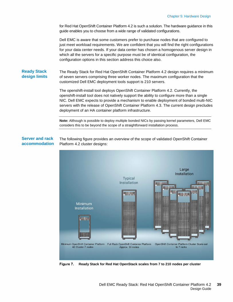
Chapter 5: Hardware Design
39 Dell EMC Ready Stack: Red Hat OpenShift Container Platform 4.2 Design Guide
for Red Hat OpenShift Container Platform 4.2 is such a solution. The hardware guidance in this
guide enables you to choose from a wide range of validated configurations.
Dell EMC is aware that some customers prefer to purchase nodes that are configured to
just meet workload requirements. We are confident that you will find the right configurations
for your data center needs. If your data center has chosen a homogenous server design in
which all the servers for a specific purpose must be of identical configuration, the
configuration options in this section address this choice also.
The Ready Stack for Red Hat OpenShift Container Platform 4.2 design requires a minimum
of seven servers comprising three worker nodes. The maximum configuration that the
customized Dell EMC deployment tools support is 210 servers.
The openshift-install tool deploys OpenShift Container Platform 4.2. Currently, the
openshift-install tool does not natively support the ability to configure more than a single
NIC. Dell EMC expects to provide a mechanism to enable deployment of bonded multi-NIC
servers with the release of OpenShift Container Platform 4.3. The current design precludes
deployment of an HA container platform infrastructure.
Note: Although is possible to deploy multiple bonded NICs by passing kernel parameters, Dell EMC
considers this to be beyond the scope of a straightforward installation process.
The following figure provides an overview of the scope of validated OpenShift Container
Platform 4.2 cluster designs:
Ready Stack for Red Hat OpenStack scales from 7 to 210 nodes per cluster
Ready Stack
design limits
Server and rack
accommodation

Chapter 5: Hardware Design
40 Dell EMC Ready Stack: Red Hat OpenShift Container Platform 4.2 Design Guide
This design guide uses a server node base configuration for the PowerEdge R640 and
PowerEdge R740xd server nodes that can be used in each node role. While you could use
PowerEdge R740xd servers for the CSAH, master, worker, and higher (OpenShift
Container Platform 4.3) storage node roles, we do not recommend doing so.
Appendix A shows the PowerEdge Server baseline configurations that we used in the
design. The following table shows the hardware configuration that is required to build the
cluster design that we used for our validation work:
Table 9. Cluster configuration: Number of servers
Node name Quantity Configuration
CSAH 1 Dell EMC PowerEdge R640 server configuration
Master 3 Dell EMC PowerEdge R640 server configuration
Worker 3 or more* Dell EMC PowerEdge R640 or R740xd server configuration
Storage** 3 or more Dell EMC PowerEdge R640 or R740xd server configuration
*During installation, one node is used to create the bootstrap node that is needed to deploy the master nodes. The
bootstrap node can be converted to a worker node.
**The storage nodes are not required for OpenShift Container Platform 4.2. They are shown here if you want to
include integrated storage for your OpenShift cluster following the release of OpenShift Container Platform 4.3.
The following table provides additional cluster configuration information:
Table 10. Cluster configuration reference information
Quantity Description Dell EMC Reference
1* Rack enclosure:
APC AR3300 NetShelter SZ 42U
APC AR3300 NetShelter SZ 42U
1* Management switch:
Dell EMC Networking S3048-ON
Dell EMC PowerSwitch S series 1 GbE switches
2* Data switch:
Dell EMC Networking S5248F-ON
or
Dell EMC Networking S5232-ON
Dell EMC PowerSwitch S series 25/40/50/100 GbE switches
7 - 210* • CSAH, Master:
Dell EMC PowerEdge R640
• Worker nodes:
Dell EMC PowerEdge R640
or
Dell EMC PowerEdge R740xd
PowerEdge R640 Rack Server
or
PowerEdge R740xd Rack Server
2-4* Power distribution unit:
APC metered rack PDU 17.2 kW
APC metered rack PDU 17.2 kW
*Rack enclosures and power distribution units are site-specific. Review the physical dimensions and power
requirements during a site survey.
Server, switch,
and rack
configuration

Chapter 5: Hardware Design
41 Dell EMC Ready Stack: Red Hat OpenShift Container Platform 4.2 Design Guide
Validated hardware configuration options
We used various server configurations for the Dell EMC Ready Stack for Red Hat
OpenShift Contain Platform. Dell EMC recommends selecting server configurations that
are known to provide both a satisfactory deployment experience and to meet or exceed
Day-2 operating experience expectations. This section provides guidelines for Intel
microprocessor selection, memory configuration, local (on-server) disk storage, and
network configuration.
While it is tempting to minimize container ecosystem node costs, as the size of the cluster
expands over time, higher overall hardware and operating costs might result. As Table 7
shows, the lower-cost node configuration requires 40 servers to meet workload
requirements while the higher-cost configuration requires 14 servers. Therefore, the lower-
cost configuration is approximately 35 percent more. The total cost of the servers that are
necessary to meet workload requirements is nearly double that of the higher performing
servers. Higher density computing is generally the most prudent choice.
The Intel Xeon Gold processor family provides performance, advanced reliability, and
hardware-enhanced security for demanding compute, network, and storage workloads.
Dell EMC recommends Intel Xeon Gold series CPUs in the range of the 6226 to 6252
models. This selection is based on experience gained from deployment and operation of
OpenShift Container Platform 4.2 running on Dell EMC PowerEdge R640 and R740xd
servers. The design information in this document is based on clusters of servers with either
Intel Gold 6240 or Intel Gold 6238 processors.
When selecting a processor, consider the following recommendations:
• Processor core count—The processor core count must be adequate to ensure
satisfactory performance of workload operations.
• Thermal design power (TDP)—The CPU must be suitable for the amount of heat
that needs to be removed from the server through the heat sinks and cooling air flow.
• Ability to dissipate heat—During validation work with high core-count, high TDP
processors, the thermal delta (air discharge temperature minus air intake
temperature) across a server was recorded at 65°F. Excessive air discharge
(egress) temperature from the server might lead to a premature server-component or
system failure.
When ordering and configuring your PowerEdge servers, see the Dell EMC PowerEdge
R640 Technical Guide and Dell EMC PowerEdge R740 and R740xd Technical Guide. For
CPU information, see Intel Xeon Gold Processors.
The Dell EMC engineering team designated 192, 384, or 768 GB RAM as the best choice
based on memory usage, DIMM module capacity for the current cost, and likely
obsolescence during the server life cycle. We chose a mid-range memory configuration of
384 GB RAM to ensure that the memory for each CPU has multiples of three banks of
DIMM slots populated to ensure maximum memory-access cycle speed. You can alter the
memory configuration to meet your budgetary constraints and operating needs.
Selecting the
server
processors
Per-node
memory
configuration
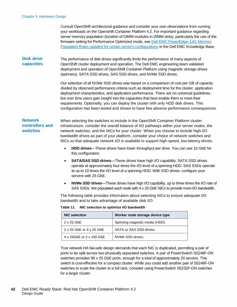
Chapter 5: Hardware Design
42 Dell EMC Ready Stack: Red Hat OpenShift Container Platform 4.2 Design Guide
Consult OpenShift architectural guidance and consider your own observations from running
your workloads on the Openshift Container Platform 4.2. For important guidance regarding
server memory population (location of DIMM modules in DIMM slots), particularly the use of the
firmware setting for Performance Optimized mode, see Dell EMC PowerEdge–14G Memory
Population Rules updated for certain server's configurations in the Dell EMC Knowledge Base.
The performance of disk drives significantly limits the performance of many aspects of
OpenShift cluster deployment and operation. The Dell EMC engineering team validated
deployment and operation of OpenShift Container Platform using magnetic storage drives
(spinners), SATA SSD drives, SAS SSD drives, and NVMe SSD drives.
Our selection of all NVMe SSD drives was based on a comparison of cost per GB of capacity
divided by observed performance criteria such as deployment time for the cluster, application
deployment characteristics, and application performance. There are no universal guidelines,
but over time users gain insight into the capacities that best enable them to meet their
requirements. Optionally, you can deploy the cluster with only HDD disk drives. This
configuration has been tested and shown to have few adverse performance consequences.
When selecting the switches to include in the OpenShift Container Platform cluster
infrastructure, consider the overall balance of I/O pathways within your server nodes, the
network switches, and the NICs for your cluster. When you choose to include high-I/O
bandwidth drives as part of your platform, consider your choice of network switches and
NICs so that adequate network I/O is available to support high-speed, low-latency drives:
• HDD drives—These drives have lower throughput per drive. You can use 10 GbE for
this configuration.
• SATA/SAS SSD drives—These drives have high I/O capability. SATA SSD drives
operate at approximately four times the I/O level of a spinning HDD. SAS SSDs operate
at up to 10 times the I/O level of a spinning HDD. With SSD drives, configure your
servers with 25 GbE.
• NVMe SSD drives—These drives have high I/O capability, up to three times the I/O rate of
SAS SSDs. We populated each node with 4 x 25 GbE NICs to provide more I/O bandwidth.
The following table provides information about selecting NICs to ensure adequate I/O
bandwidth and to take advantage of available disk I/O:
Table 11. NIC selection to optimize I/O bandwidth
NIC selection Worker node storage device type
2 x 25 GbE Spinning magnetic media (HDD).
2 x 25 GbE or 4 x 25 GbE SATA or SAS SSD drives.
4 x 25GbE or 2 x 100 GbE NVMe SSD drives.
True network HA fail-safe design demands that each NIC is duplicated, permitting a pair of
ports to be split across two physically separated switches. A pair of PowerSwitch S5248F-ON
switches provides 96 x 25 GbE ports, enough for a total of approximately 20 servers. This
switch is cost-effective for a compact cluster. While you could add another pair of S5248F-ON
switches to scale the cluster to a full rack, consider using PowerSwitch S5232F-ON switches
for a larger cluster.
Disk drive
capacities
Network
controllers and
switches
Chapter 5: Hardware Design
43 Dell EMC Ready Stack: Red Hat OpenShift Container Platform 4.2 Design Guide
The PowerSwitch S5232F-ON provides 32 x 100 Gbe ports. When used with a 4-way QSFP28
to SFP28, a pair of the switches provides up to 256 x 25 GbE endpoints, more than enough for
a rack full of servers in the cluster before more complex network topologies are required.
Note: Dell EMC recommends purchasing servers with enough network (NIC) ports to accommodate
near-future deployment needs. This design guide does not address the deployment of multi-NIC
teaming (bonding) because of issues experienced during our validation test work. We expect these
issues to be fully resolved by the time that OpenShift Container Platform 4.3 is released. Therefore,
we recommend provisioning your server nodes and switches to fully enable HA network
deployment from the outset.
NFV-centric data centers require low latency in all aspects of container ecosystem design
for application deployment. This requirement means that you must give particular attention
to selecting low-latency components throughout the OpenShift cluster. Dell EMC strongly
recommends using only NVMe drives, NFV-centric versions of Intel CPUs, and, at a
minimum, the Dell EMC PowerSwitch S5232F-ON switch. Consult the Dell EMC Service
Provider support team for specific guidance.
Dell EMC strongly recommends that all servers be equipped with redundant power
supplies and that power cabling provides redundant power to the servers. Configure each
rack with pairs of power distribution units (PDUs). For consistency, connect all right-most
power supply units (PSUs) to a right-side PDU and all left-most PSUs to a left-side PDU.
Use as many PDUs as you need, in pairs. Each PDU must have an independent
connection to the data center power bus.
The following figure shows an example of the power configuration that is designed to
assure redundant power supply to each cluster device.
Low latency in
an NFV
environment
Power
configuration
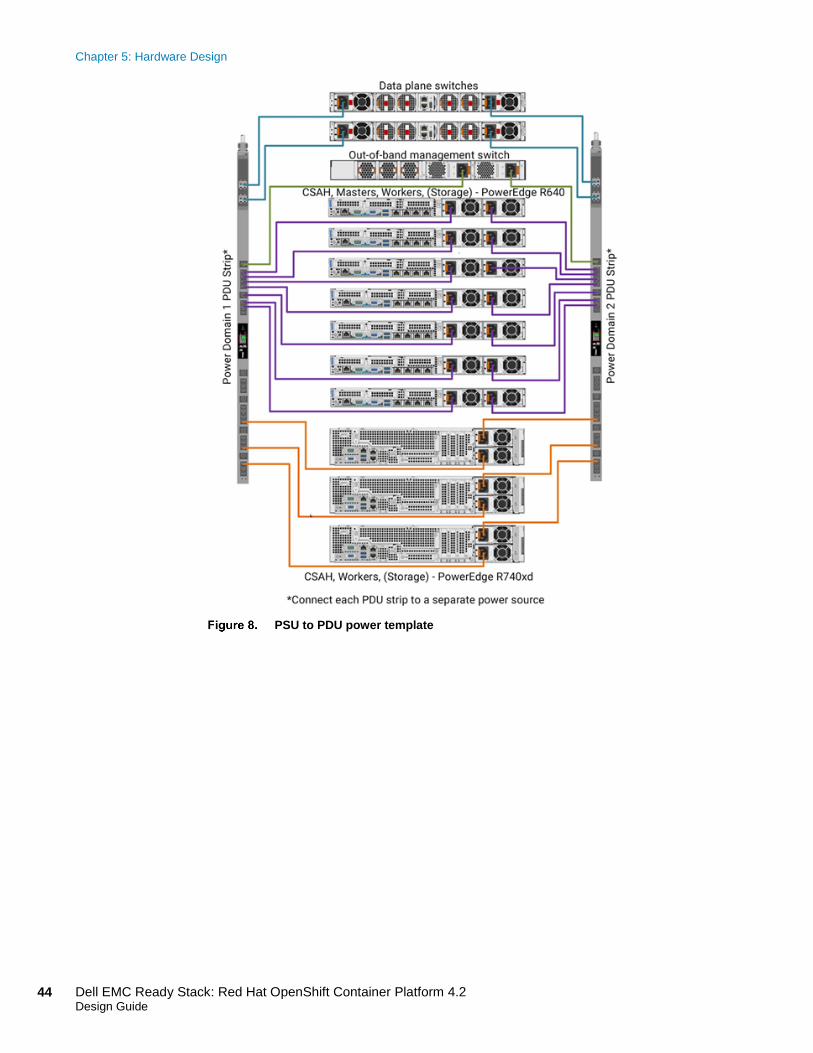
Chapter 5: Hardware Design
44 Dell EMC Ready Stack: Red Hat OpenShift Container Platform 4.2 Design Guide
PSU to PDU power template

Chapter 6: Use Cases
45 Dell EMC Ready Stack: Red Hat OpenShift Container Platform 4.2 Design Guide
Chapter 6 Use Cases
This chapter presents the following topics:
Introduction to use cases ................................................................................. 46
Telco industry ................................................................................................... 47
Cloud service providers ................................................................................... 49
Financial services industry .............................................................................. 50
Data analytics and artificial intelligence .......................................................... 51

Chapter 6: Use Cases
46 Dell EMC Ready Stack: Red Hat OpenShift Container Platform 4.2 Design Guide
Introduction to use cases
The term “use case” is often used interchangeably with the term “workload.” This guide
makes a clear distinction between these two terms. Here, a use case represents a
situational environment, whereas a workload represents an instance of use within a
situational environment.
For example, a truck that is designed to carry a large object is analogous to a device that is
designed to enable handling a situational environment. This truck might be used to pick up
a carton of milk from a store, or it might be used to convey a large machine part from point
A to point B. Using a large truck (the situational environment tool) might be considered
inappropriate for the task of picking up a carton of milk; however, it might be considered
highly appropriate for the transportation of a large machine part—the design of the truck
and its use are a good match for this purpose.
Kubernetes containers are component tools that are generally used within a situational
environment (use case) so that a particular application (workload) can be handled
efficiently and cost-effectively. A use case defines platform environment needs, while a
workload is a task that has dependencies that must be provisioned so that the use case
has the capacity and ability to accommodate the workload.
Containers are vehicles that carry and enable the development and execution of cloud-
native software. Generally, they employ the new “declarative” software design model as
part of a distributed-computation platform environment. Here are some key considerations
in answer to the frequently asked question, “How can I move my workload to containers?”:
• Ensure that the hardware platform is well-designed for your container
ecosystem needs—Select the right hardware infrastructure to enable all use-case
workloads to be run at the right level of return on investment. The economics of
platform infrastructure design are intensified in the container ecosystem because of
the large number of active infrastructure software components, their resource
overheads, and the trade-off between node cost (CapEx) and operating cost (OpEx).
• “Lift and shift” existing applications into a cloud-native container
environment—You can migrate existing applications into more a cloud-native
container environment. This environment delivers some of the natural benefits of
operating system virtualization but also confers the full benefits of declarative-
designed modular, container-based software architecture.
• Refactor older software code—Refactoring requires much more work than lift-and-
shift migration. Refactoring provides access to the full benefits of a container
ecosystem but at a higher cost.
• Develop new cloud-native applications—Like refactoring, this approach gives
your organization the full benefits of a container ecosystem.
• Build distributed, location-independent, microservices-based cloud-native
applications—Distributed cloud-native microservices are more easily isolated,
deployed, and scaled by using discrete container instances.
• Adopt new tools to support continuous integration and deployment (CI/CD)—
DevOps teams, in particular, appreciate the advantages of automated build, test, and
Workload
compared with
use case
Containers
Chapter 6: Use Cases
47 Dell EMC Ready Stack: Red Hat OpenShift Container Platform 4.2 Design Guide
deployment operations so that container images can be handled only once through
the entire concept-to-production lifecycle.
• Simplify and automate repetitive tasks and activities—Automated orchestration
of frequently executed operations reduces management overhead and increases the
agility and time-value of the DevOps process.
The following use-case examples are minimal and are intended only to show you some of
the decisions that you might face with your unique container-ecosystem use cases.
Telco industry
A typical telecommunications company sells telco-oriented applications as a service to its
consumers. Telco use-case requirements vary depending on the virtual network functions
(VNFs) that are being serviced. These include:
• Content delivery network (CDN)
• Edge infrastructure and towers of power
• NFV management and operations (NFV-MANO)
• Software-defined networking (SDN) and SD-WAN management
• Radio access networks (RAN) and 5G, and their component service infrastructures
• Multi-access Edge Computing (MEC)
• Core network and 5G Next Generation Core (NGC)
The telco industry seeks to define and develop an infinitely flexible, fully software-defined
and location-independent operational infrastructure. This vision is coming together, and the
capabilities of the container ecosystem are steadily growing along with it.
A telco infrastructure is like an enterprise data center where hardware is fully owned and
managed, in other words, fully under in-house control. The data center does not share
system and infrastructure resources with external parties. Access to enterprise and telco
infrastructure management functions is limited to a few internal administrators, and
administration is limited to a single role.
This use case serves to identify some key design factors for a telco container platform.
Online video consumption has grown in recent years. High-quality video delivery over
public networks requires a CDN. To handle growth, many operators are considering the
virtualization of the CDN, giving them an ability to scale CDN on-demand. CDN
virtualization permits simple provisioning and sharing of resources with other telco
services, simplifying operations and avoiding costly dedicated infrastructure.
Introduction
Content delivery
network
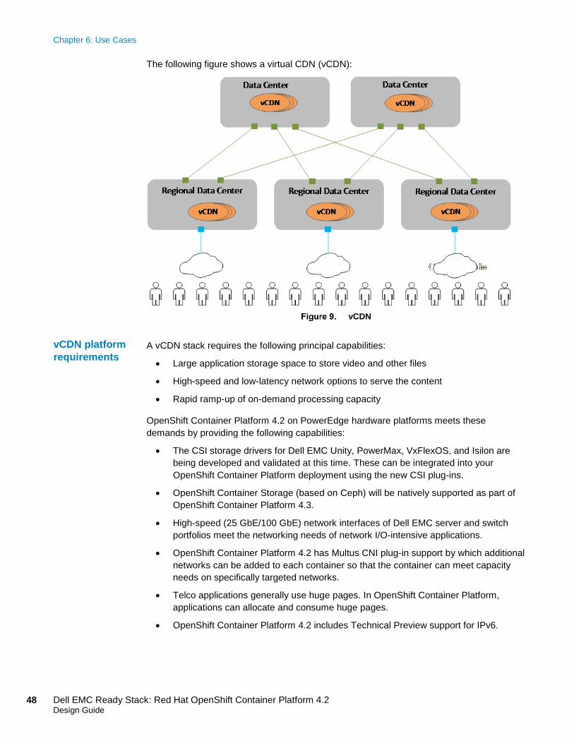
Chapter 6: Use Cases
48 Dell EMC Ready Stack: Red Hat OpenShift Container Platform 4.2 Design Guide
The following figure shows a virtual CDN (vCDN):
vCDN
A vCDN stack requires the following principal capabilities:
• Large application storage space to store video and other files
• High-speed and low-latency network options to serve the content
• Rapid ramp-up of on-demand processing capacity
OpenShift Container Platform 4.2 on PowerEdge hardware platforms meets these
demands by providing the following capabilities:
• The CSI storage drivers for Dell EMC Unity, PowerMax, VxFlexOS, and Isilon are
being developed and validated at this time. These can be integrated into your
OpenShift Container Platform deployment using the new CSI plug-ins.
• OpenShift Container Storage (based on Ceph) will be natively supported as part of
OpenShift Container Platform 4.3.
• High-speed (25 GbE/100 GbE) network interfaces of Dell EMC server and switch
portfolios meet the networking needs of network I/O-intensive applications.
• OpenShift Container Platform 4.2 has Multus CNI plug-in support by which additional
networks can be added to each container so that the container can meet capacity
needs on specifically targeted networks.
• Telco applications generally use huge pages. In OpenShift Container Platform,
applications can allocate and consume huge pages.
• OpenShift Container Platform 4.2 includes Technical Preview support for IPv6.
vCDN platform
requirements
Chapter 6: Use Cases
49 Dell EMC Ready Stack: Red Hat OpenShift Container Platform 4.2 Design Guide
Container ecosystem clusters in telco operations are likely to be large, spanning multiple
racks. OpenShift Container Platform running on PowerEdge servers scales to
approximately 210 nodes (seven racks when you use PowerEdge R640 servers). We
highly recommend the use of leaf-spine networking when scaling to more than three racks
per cluster. Our research provides a high degree of confidence for up to seven racks of
servers. Although the cluster can be scaled beyond seven racks, undertake this effort only
as a custom engineering project. The deployment of large clusters requires significant
modification of the Ansible playbooks that we generated to facilitate large-scale
deployment.
Cloud service providers
Cloud service providers typically expose parts of the management functionality to their
external clients, for example, by instantiating Kubernetes clusters or allocating persistent
storage, possibly even (data center) network configurations. The management
infrastructure must provide different “views” for each key administrative role and its
assigned users. At a minimum, these roles include: provider administrator, tenant
administrator, and tenant user.
Access control has implications for what multitenancy means throughout the infrastructure:
Portal access/views, logging information, and usage information must be linked to role. For
example:
• A provider administrator must be able to see the usage/metering information of the
entire infrastructure.
• A tenant administrator needs to see only the infrastructure assigned to that tenant.
• The tenant users only require access to assets and resources that they are permitted
to manage.
OpenShift Container Platform 4.2 role-based access control (RBAC) can be tied to your
Microsoft Active Directory identity management environment. This link enables control over
user and group access to the container ecosystem infrastructure and services, providing a
good foundation for multitenancy support.
OpenShift Container Platform 4.2 is built on the concept that each project that runs within a
cluster can be isolated from every other project. The project manager must be granted the
administrative privilege to be able to see any other project in the cluster.
Cloud service providers typically require the ability to monitor and report on system
utilization. OpenShift Container Platform 4.2 includes Prometheus system monitoring and
metering, and provides capability for extensive data logging. For more information about
about obtaining cluster resource consumption to drive usage billing through third-party
application software, see the following Red Hat documentation:
• About cluster monitoring
• Examples of using metering
• About cluster logging and OpenShift Container Platform
Introduction
Access control
Security and
isolation
Performance
monitoring and
logging
Chapter 6: Use Cases
50 Dell EMC Ready Stack: Red Hat OpenShift Container Platform 4.2 Design Guide
Financial services industry
Financial service providers that are moving from traditional monolithic applications are
redefining the services that they offer their customers. Some report the need to develop
and deploy stateful data services. This need can be a challenge in the cloud-native
technology area, where most application containers are implemented with the presumption
that container storage is ephemeral and the drive is towards stateless data services.
Large financial service providers, as well as financial transaction trading houses, tend to
deploy multiple Kubernetes clusters to limit the risk of loss of service through cluster
outage. Financial service providers might say that having multiple Kubernetes clusters
enables load-shedding and load-distribution for greater service integrity assurance. The
following information shows that OpenShift Container Platform provides better functionality
than many practitioners are currently aware of.
Key concerns that financial organizations have raised with Dell EMC include:
• Security and regulatory compliance—Red Hat maintains a web page that
addresses security and compliance. For more information, see Red Hat’s Container
Security Guide.
• Potential noisy-neighbor problem—Container deployment with Kubernetes and
OpenShift minimizes the noisy-neighbor risk. Kubernetes, and OpenShift in
particular, deploy containers so that each application container environment runs
within its own end-to-end isolated network. This method uses tagged VLANs or runs
over GRE tunnels.
• Ability to host mixed-transaction workloads—OpenShift 4.2 application container
workloads are deployed as a project. Each project may be assigned one or more
administrators. The project manager defines administrative roles, with RBAC limits
placed on the functions of each role. Projects are typically isolated from each other
and are unaware of the existence of a neighboring project unless the network
administrator permits otherwise. For more information about multitenancy
configuration, see the Configuring network isolation using OpenShift SDN in the
OpenShift 4.2 documentation.
• Reliable scale-out and scale-back—Established capabilities of Kubernetes clusters
and of OpenShift in particular are reliable configuration scale-out and scale-back.
• Kubernetes cluster federation and services management support—The
OpenShift blog article Kubernetes Guideposts for 2019 provides useful insights into
Red Hat and general Kubernetes community work that address cluster federation.
Particular worker nodes of similar hardware configuration can be assigned to their
own OpenShift MachineType, and containers can be configured so that they are
deployed with affinity to a MachineType constraint. This technique is used in
combination with RBAC limits that can be placed on certain nodes so that an
OpenShift tenant can be restricted to a subset of worker nodes. This option provides
considerable flexibility in cluster design and can be used to avoid multicluster
federation requirements.
OpenShift Container Platform 4.2 includes release of the OpenShift Service Mesh.
With OpenShift Service Mesh, you can connect, secure, and monitor microservices
in your OpenShift Container Platform environment.
Introduction
Addressing
concerns
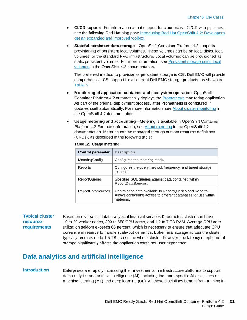
Chapter 6: Use Cases
51 Dell EMC Ready Stack: Red Hat OpenShift Container Platform 4.2 Design Guide
• CI/CD support−For information about support for cloud-native CI/CD with pipelines,
see the following Red Hat blog post: Introducing Red Hat OpenShift 4.2: Developers
get an expanded and improved toolbox.
• Stateful persistent data storage—OpenShift Container Platform 4.2 supports
provisioning of persistent local volumes. These volumes can be on local disks, local
volumes, or the standard PVC infrastructure. Local volumes can be provisioned as
static persistent volumes. For more information, see Persistent storage using local
volumes in the OpenShift 4.2 documentation.
The preferred method to provision of persistent storage is CSI. Dell EMC will provide
comprehensive CSI support for all current Dell EMC storage products, as shown in
Table 5.
• Monitoring of application container and ecosystem operation−OpenShift
Container Platform 4.2 automatically deploys the Prometheus monitoring application.
As part of the original deployment process, after Prometheus is configured, it
updates itself automatically. For more information, see About cluster monitoring in
the OpenShift 4.2 documentation.
• Usage metering and accounting—Metering is available in OpenShift Container
Platform 4.2 For more information, see About metering in the OpenShift 4.2
documentation. Metering can be managed through custom resource definitions
(CRDs), as described in the following table:
Table 12. Usage metering
Control parameter Description
MeteringConfig Configures the metering stack.
Reports Configures the query method, frequency, and target storage location.
ReportQueries Specifies SQL queries against data contained within ReportDataSources.
ReportDataSources Controls the data available to ReportQueries and Reports. Allows configuring access to different databases for use within metering.
Based on diverse field data, a typical financial services Kubernetes cluster can have
10 to 20 worker nodes, 200 to 650 CPU cores, and 1.2 to 7 TB RAM. Average CPU core
utilization seldom exceeds 65 percent, which is necessary to ensure that adequate CPU
cores are in reserve to handle scale-out demands. Ephemeral storage across the cluster
typically requires up to 1.5 TB across the whole cluster; however, the latency of ephemeral
storage significantly affects the application container user experience.
Data analytics and artificial intelligence
Enterprises are rapidly increasing their investments in infrastructure platforms to support
data analytics and artificial intelligence (AI), including the more specific AI disciplines of
machine learning (ML) and deep learning (DL). All these disciplines benefit from running in
Typical cluster
resource
requirements
Introduction

Chapter 6: Use Cases
52 Dell EMC Ready Stack: Red Hat OpenShift Container Platform 4.2 Design Guide
containerized environments. The benefits of running these applications on OpenShift
Container Platform apply to developers, data scientists, and IT operators.
For simplicity, we use “data analytics as a service” (“DAaaS”) to refer to analytics and AI as
operated and instantiated in a containerized environment. OpenShift Container Platform
enables operators to create a DAaaS environment as an extensible analytics platform with
a private cloud-based delivery model. This delivery model makes various tools available for
data analytics and can be configured to efficiently process and analyze huge quantities of
heterogeneous data from shared data stores.
The data analytics life cycle, and particularly the ML life cycle, is a multiphase process to
integrate large volumes and varieties of data, abundant compute power, and open source
languages, libraries, and tools to build intelligent applications and predictive outcomes. At a
high level, the life cycle comprises these steps:
• Data acquisition and preparation—Ensures that the input data is complete and of
high quality
• Modelling creation—Includes training, testing, and selection of the model with the
highest prediction accuracy
• Model deployment—Includes inferencing in the application development and
operations processes
Key challenges facing data scientists
Data scientists and engineers are primarily responsible for developing modeling methods
that ensure the selected outcome continues to provide the highest prediction accuracy. The
key challenges that data scientists face include:
• Selection and deployment of the right AI tools (such as Apache Spark, TensorFlow,
PyTorch, and so on)
• Complexities and time required to train, test, select, and retrain the AI model that
provides the highest prediction accuracy
• Slow execution of AI modelling and inferencing tasks because of lack of hardware
acceleration
• Limited IT operations to provision and manage infrastructure
• Collaboration with data engineers and software developers to ensure input data
hygiene and successful AI model deployment in application development processes
Containers and Kubernetes are key to accelerating the data analytics life cycle because
they provide data scientists and IT operators with the agility, flexibility, portability, and
scalability needed to train, test, and deploy ML models.
OpenShift Container Platform provides all these benefits. Through its integrated DevOps
capabilities and integration with hardware accelerators, it enables better collaboration
between data scientists and software developers. It also accelerates the roll-out of
analytics applications to departments as needed.
The benefits include the ability to:
• Empower data scientists with a consistent, self-service-based, cloud-like experience:
Chapter 6: Use Cases
53 Dell EMC Ready Stack: Red Hat OpenShift Container Platform 4.2 Design Guide
▪ Gives data scientists the flexibility and portability to use containerized ML tools
of their choice to quickly build, scale, reproduce, and share ML modeling results
in a consistent way with peers and software developers
▪ Eliminates dependency on IT to provision infrastructure for iterative, compute-
intensive ML modeling tasks
• Accelerate compute-intensive ML modeling and inferencing jobs
On-demand access to high performance hardware can seamlessly meet the high
compute resource requirements to help determine the best ML model, providing the
highest prediction accuracy.
• Streamline the development and operations of intelligent applications
Extending OpenShift DevOps automation capabilities to the ML lifecycle enables
collaboration between data scientists, software developers, and IT operations so that
ML models can be quickly integrated into the development of intelligent applications.
This feature helps boost productivity and simplify life cycle management for ML-
powered intelligent applications.
One example of ML on OpenShift Container Platform is the work done by Dell EMC and
Red Hat to deploy Kubeflow on OpenShift.
Kubeflow is an open-source Kubernetes-native platform for ML workloads that enables
enterprises to accelerate their ML/DL projects. Based originally on Google’s use of
TensorFlow on Kubernetes, Kubeflow is a composable, scalable, portable ML stack that
includes components and contributions from a variety of sources and organizations. It
bundles popular ML/DL frameworks such as TensorFlow, MXNet, Pytorch, and Katib with a
single deployment binary file. By running Kubeflow on OpenShift Container Platform, you
can quickly operationalize a robust ML pipeline.
The software stack is only part of the solution. You also need high-performance servers,
storage, and network infrastructure to deliver the stack’s full capability. Enterprises
investing in custom infrastructure platforms to support the exploration of such AI
technologies sometimes use ad hoc hardware implementations that are outside
mainstream data center systems infrastructure. The ability to integrate production-grade,
experimental AI technologies in well-defined platforms facilitates wider adoption. This
scenario is where Dell EMC Ready Stack for OpenShift Container Platform comes in.
For more information, see the Machine Learning Using the Dell EMC Ready Architecture
for Red Hat OpenShift Container Platform White Paper (this publication is based on the
previous release of OpenStack).
For more information about Kubeflow, see Kubeflow: The Machine Learning Toolkit for
Kubernetes.
Kubeflow ML on
OpenShift

Chapter 7: References
54 Dell EMC Ready Stack: Red Hat OpenShift Container Platform 4.2 Design Guide
Chapter 7 References
This chapter presents the following topics:
Dell EMC documentation .................................................................................. 55
Red Hat documentation .................................................................................... 55
Other resources ................................................................................................ 55
Chapter 7: References
55 Dell EMC Ready Stack: Red Hat OpenShift Container Platform 4.2 Design Guide
Dell EMC documentation
The following Dell EMC resources provide additional and relevant information. Access to
these documents depends on your login credentials. If you do not have access to a
document, contact your Dell EMC representative.
• Dell EMC Ready Stack Converged Infrastructure
• Dell EMC Info Hub for Red Hat OpenShift Container Platform
• Dell EMC PowerEdge R640 Technical Guide
• Dell EMC PowerEdge R740 and R740xd Technical Guide
• Machine Learning Using the Dell EMC Ready Architecture for Red Hat OpenShift
Container Platform (this publication is based on the previous release of OpenStack).
Red Hat documentation
The following Red Hat resources provide additional and relevant information:
• OpenShift Container Platform 4.2 Documentation
• Understanding the Operator Lifecycle Manager
• Container Security Guide
• Understanding Red Hat OpenShift Service Mesh
• About cluster monitoring
• Examples of using metering
• About cluster logging and OpenShift Container Platform
Other resources
The following resources provide additional and relevant information:
• Intel Xeon Gold Processors
• Kubernetes Guideposts for 2019
• Kubeflow: The Machine Learning Toolkit for Kubernetes
• Prometheus: From Metrics to Insight
Appendix A: Dell EMC PowerEdge BOMs
56 Dell EMC Ready Stack: Red Hat OpenShift Container Platform 4.2 Design Guide
Appendix A Dell EMC PowerEdge BOMs
This appendix presents the following topics:
Dell EMC PowerEdge R640 node BOM ............................................................ 57
Dell EMC PowerEdge R740xd node BOM ........................................................ 58
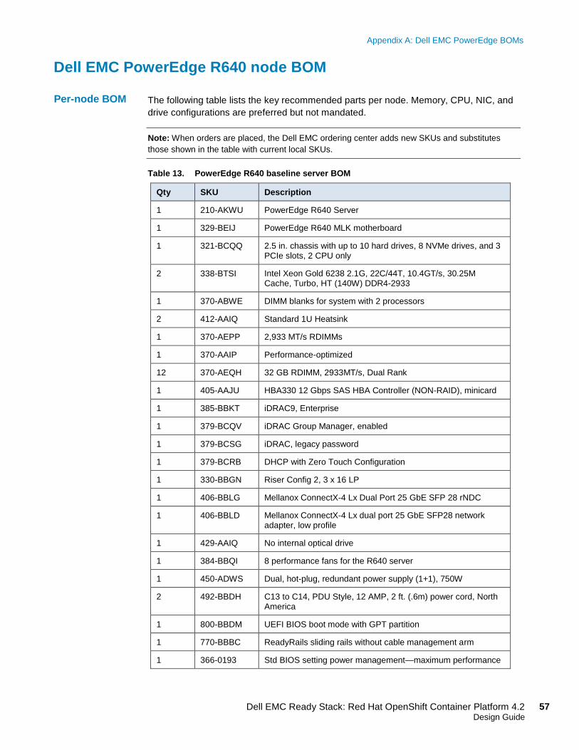
Appendix A: Dell EMC PowerEdge BOMs
57 Dell EMC Ready Stack: Red Hat OpenShift Container Platform 4.2 Design Guide
Dell EMC PowerEdge R640 node BOM
The following table lists the key recommended parts per node. Memory, CPU, NIC, and
drive configurations are preferred but not mandated.
Note: When orders are placed, the Dell EMC ordering center adds new SKUs and substitutes
those shown in the table with current local SKUs.
Table 13. PowerEdge R640 baseline server BOM
Qty SKU Description
1 210-AKWU PowerEdge R640 Server
1 329-BEIJ PowerEdge R640 MLK motherboard
1 321-BCQQ 2.5 in. chassis with up to 10 hard drives, 8 NVMe drives, and 3 PCIe slots, 2 CPU only
2 338-BTSI Intel Xeon Gold 6238 2.1G, 22C/44T, 10.4GT/s, 30.25M Cache, Turbo, HT (140W) DDR4-2933
1 370-ABWE DIMM blanks for system with 2 processors
2 412-AAIQ Standard 1U Heatsink
1 370-AEPP 2,933 MT/s RDIMMs
1 370-AAIP Performance-optimized
12 370-AEQH 32 GB RDIMM, 2933MT/s, Dual Rank
1 405-AAJU HBA330 12 Gbps SAS HBA Controller (NON-RAID), minicard
1 385-BBKT iDRAC9, Enterprise
1 379-BCQV iDRAC Group Manager, enabled
1 379-BCSG iDRAC, legacy password
1 379-BCRB DHCP with Zero Touch Configuration
1 330-BBGN Riser Config 2, 3 x 16 LP
1 406-BBLG Mellanox ConnectX-4 Lx Dual Port 25 GbE SFP 28 rNDC
1 406-BBLD Mellanox ConnectX-4 Lx dual port 25 GbE SFP28 network adapter, low profile
1 429-AAIQ No internal optical drive
1 384-BBQI 8 performance fans for the R640 server
1 450-ADWS Dual, hot-plug, redundant power supply (1+1), 750W
2 492-BBDH C13 to C14, PDU Style, 12 AMP, 2 ft. (.6m) power cord, North America
1 800-BBDM UEFI BIOS boot mode with GPT partition
1 770-BBBC ReadyRails sliding rails without cable management arm
1 366-0193 Std BIOS setting power management—maximum performance
Per-node BOM
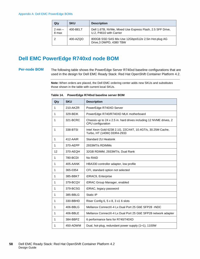
Appendix A: Dell EMC PowerEdge BOMs
58 Dell EMC Ready Stack: Red Hat OpenShift Container Platform 4.2 Design Guide
Qty SKU Description
2 min – 8 max
400-BELT Dell 1.6TB, NVMe, Mixed Use Express Flash, 2.5 SFF Drive, U.2, P4610 with Carrier
2 400-AZQO 800GB SSD SAS Mix Use 12Gbps512e 2.5in Hot-plug AG Drive,3 DWPD, 4380 TBW
Dell EMC PowerEdge R740xd node BOM
The following table shows the PowerEdge Server R740xd baseline configurations that are
used in the design for Dell EMC Ready Stack: Red Hat OpenShift Container Platform 4.2.
Note: When orders are placed, the Dell EMC ordering center adds new SKUs and substitutes
those shown in the table with current local SKUs.
Table 14. PowerEdge R740xd baseline server BOM
Qty SKU Description
1 210-AKZR PowerEdge R740XD Server
1 329-BEIK PowerEdge R740/R740XD MLK motherboard
1 321-BCRC Chassis up to 24 x 2.5 in. hard drives including 12 NVME drives, 2 CPU configuration
1 338-BTSI Intel Xeon Gold 6238 2.1G, 22C/44T, 10.4GT/s, 30.25M Cache, Turbo, HT (140W) DDR4-2933
1 412-AAIR Standard 2U Heatsink
1 370-AEPP 2933MT/s RDIMMs
12 370-AEQH 32GB RDIMM, 2933MT/s, Dual Rank
1 780-BCDI No RAID
1 405-AANK HBA330 controller adapter, low profile
1 365-0354 CFI, standard option not selected
1 385-BBKT iDRAC9, Enterprise
1 379-BCQV iDRAC Group Manager, enabled
1 379-BCSG iDRAC, legacy password
1 385-BBLG Static IP
1 330-BBHD Riser Config 6, 5 x 8, 3 x1 6 slots
1 406-BBLG Mellanox ConnectX-4 Lx Dual Port 25 GbE SFP28 rNDC
1 406-BBLE Mellanox ConnectX-4 Lx Dual Port 25 GbE SFP28 network adapter
1 384-BBPZ 6 performance fans for R740/740XD
1 450-ADWM Dual, hot-plug, redundant power supply (1+1), 1100W
Per-node BOM

Appendix A: Dell EMC PowerEdge BOMs
59 Dell EMC Ready Stack: Red Hat OpenShift Container Platform 4.2 Design Guide
Qty SKU Description
1 492-BBDH C13 to C14, PDU Style, 12 AMP, 2 ft (.6m) power cord, North America
1 325-BCHU PowerEdge 2U standard bezel
1 800-BBDM UEFI BIOS Boot Mode with GPT partition
1 770-BBBQ ReadyRails sliding rails without cable management arm
1 366-0193 Std Bios setting power management - maximum performance
For storage nodes, select one of the following rows.
Up to 24
Check part at order time
800 GB, 1.92 TB, or 3.84 TB SSD SAS Mix Use 12 Gbps 512e 2.5 in. hot-plug AG drive, 3 DWPD, 4380 TBW, CK
Up to 12
Check part at order time
Dell 1.6 TB, 3.2 TB or 6.4 TB, NVMe, mixed use express flash, 2.5 SFF drive, U.2, P4610 with Carrier, CK