dell™ sonicwall™ x-series...
TRANSCRIPT

Dell™ SonicWALL™ X-Series Solution Deployment Guide
Copyright© 2016 Dell Inc. All rights reserved.
This product is protected by U.S. and international copyright and intellectual property laws. Dell™, the Dell logo, and SonicWALL are trademarks of Dell Inc. in the United States and/or other jurisdictions. All other marks and names mentioned herein may be trademarks of their respective companies.
X-Series Solution Deployment GuideUpdated - May 2016Version - 6.2.5232-003255-00 Rev A
Legend
CAUTION: A CAUTION icon indicates potential damage to hardware or loss of data if instructions are not followed.
WARNING: A WARNING icon indicates a potential for property damage, personal injury, or death.
IMPORTANT NOTE, NOTE, TIP, MOBILE, or VIDEO: An information icon indicates supporting information.

Dell SonicWALL X-Series Solution Deployment GuideContents
3
About the Dell SonicWALL X-Series Solution . . . . . . . . . . . . . . . . . . . . . . . . . . . . . . 4
Overview . . . . . . . . . . . . . . . . . . . . . . . . . . . . . . . . . . . . . . . . . . . . . . . . . . . . . . 4TZ/X-Series Solution: a unified approach . . . . . . . . . . . . . . . . . . . . . . . . . . . . . . 4Performance requirements . . . . . . . . . . . . . . . . . . . . . . . . . . . . . . . . . . . . . . . 5Features provided by the Dell SonicWALL X-Series Solution . . . . . . . . . . . . . . . . . . 6PortShield functionality and X-Series switches . . . . . . . . . . . . . . . . . . . . . . . . . . . 7PoE/PoE+ and SFP/SFP+ support . . . . . . . . . . . . . . . . . . . . . . . . . . . . . . . . . . . . 7X-Series Solution and SonicPoints . . . . . . . . . . . . . . . . . . . . . . . . . . . . . . . . . . . 8Recommended reading . . . . . . . . . . . . . . . . . . . . . . . . . . . . . . . . . . . . . . . . . . 8
Provisioning an X-Switch on a TZ series appliance . . . . . . . . . . . . . . . . . . . . . . . . . 9
Provisioning through the X-Series switch user interface . . . . . . . . . . . . . . . . . . . . . . . 9Adding a default gateway through the X-Switch UI . . . . . . . . . . . . . . . . . . . . . . . .14
Provisioning through the CLI . . . . . . . . . . . . . . . . . . . . . . . . . . . . . . . . . . . . . . . . .15Provisioning without a default gateway . . . . . . . . . . . . . . . . . . . . . . . . . . . . . . .15Provisioning with a default gateway . . . . . . . . . . . . . . . . . . . . . . . . . . . . . . . . .16
Adding the X-Series switch to SonicOS . . . . . . . . . . . . . . . . . . . . . . . . . . . . . . . . 17
Adding an extended switch . . . . . . . . . . . . . . . . . . . . . . . . . . . . . . . . . . . . . . . . .17
Deleting an extended switch . . . . . . . . . . . . . . . . . . . . . . . . . . . . . . . . . . . . . . . . .19
Configuring the X-Series Solution in various topologies . . . . . . . . . . . . . . . . . . . . 20
About topologies . . . . . . . . . . . . . . . . . . . . . . . . . . . . . . . . . . . . . . . . . . . . . . . . .20About links . . . . . . . . . . . . . . . . . . . . . . . . . . . . . . . . . . . . . . . . . . . . . . . . . .21
Connecting the X-Series switch management port to a TZ firewall . . . . . . . . . . . . . . . .21
Configuring the different topologies . . . . . . . . . . . . . . . . . . . . . . . . . . . . . . . . . . .22Configuring a common uplink . . . . . . . . . . . . . . . . . . . . . . . . . . . . . . . . . . . . . .22Configuring a dedicated uplink . . . . . . . . . . . . . . . . . . . . . . . . . . . . . . . . . . . . .25Configuring a hybrid system with common and dedicated uplink(s) . . . . . . . . . . . . .31Configuring isolated links for management and data uplinks . . . . . . . . . . . . . . . . .32Configuring HA and PortShield with dedicated uplink(s) . . . . . . . . . . . . . . . . . . . .35Configuring VLAN(s) with dedicated uplink(s) . . . . . . . . . . . . . . . . . . . . . . . . . . .37Configuring a dedicated link for SonicPoint access . . . . . . . . . . . . . . . . . . . . . . . .42
About Dell . . . . . . . . . . . . . . . . . . . . . . . . . . . . . . . . . . . . . . . . . . . . . . . . . . . . 44
Contacting Dell . . . . . . . . . . . . . . . . . . . . . . . . . . . . . . . . . . . . . . . . . . . . . . . . . .44
Technical support resources . . . . . . . . . . . . . . . . . . . . . . . . . . . . . . . . . . . . . . . . .44
Index . . . . . . . . . . . . . . . . . . . . . . . . . . . . . . . . . . . . . . . . . . . . . . . . . . . . . . . 45
Contents
1
About the Dell SonicWALL X-Series Solution
• Overview on page 4
• TZ/X-Series Solution: a unified approach on page 4
• Performance requirements on page 5
• Features provided by the Dell SonicWALL X-Series Solution on page 6
• PortShield functionality and X-Series switches on page 7
• PoE/PoE+ and SFP/SFP+ support on page 7
• X-Series Solution and SonicPoints on page 8
• Recommended reading on page 8
OverviewTopics:
• TZ/X-Series Solution: a unified approach on page 4
• Performance requirements on page 5
• Features provided by the Dell SonicWALL X-Series Solution on page 6
• PoE/PoE+ and SFP/SFP+ support on page 7
• X-Series Solution and SonicPoints on page 8
• PortShield functionality and X-Series switches on page 7
• Recommended reading on page 8
TZ/X-Series Solution: a unified approachCritical network elements, such as a firewall and switch, need to be managed, usually individually. The Dell™ SonicWALL™ X-Series Solution allows unified management of both the firewall and the switch using the firewall management interface (UI) and GMS. For example, the maximum number of interfaces available on the Dell SonicWALL TZ models range from 5 (TZ300) to 10 (TZ600). In certain deployments, the number of ports required might easily exceed the maximum number of interfaces available on the TZ appliance. With the TZ/X-Series Solution, ports on a Dell X-Series switch can be viewed as extended interfaces of the firewall, thereby increasing the number of interfaces available for use up to 96, depending on the X-Series switch. These extended ports can be portshielded or configured for high availability and treated as any other interface on the firewall.
Dell SonicWALL X-Series Solution Deployment GuideAbout the Dell SonicWALL X-Series Solution
4

Beginning in SonicOS Release 6.2.5.1, the TZ series appliances shown in Table 1 support the listed X-Series models. A TZ series appliance can provision up to two X-Series switches.
Terminology
Performance requirementsA TZ series firewall can be provisioned for a maximum of two X-series switches. If two switches are provisioned, they must be connected directly to the firewall, they cannot be cascaded, that is, one switch connected to the other switch, which is then connected to the firewall.
On TZ300/TZ400/TZ500 models, the maximum uplink bandwidth of 1G is shared by all front panel ports.
On TZ600, the maximum uplink bandwidth of 1G on:
• Internal switch 0 is shared by X0, X2, X3, X4, X5,and X7.
• Internal switch 1 is shared by X1, X6, X8, and X9.
NOTE: For complete information about X-Series switches, see the Dell™ Networking™ X1000 and X4000 Series Switches User Guide and the Dell™ Networking™ X1000 and X4000 Series Switches Getting Started Guide.
Table 1. X-Series switches supported by TZ series appliances
These TZ Series appliances
• TZ600
• TZ500/TZ500W
• TZ400/TZ400W
• TZ300/TZ300W
Support these X-Series switches
• X1008/X1008P
• X1018/X1018P
• X1026/X1026P
• X1052/X1052P
• X4012
NOTE: The X-Series Solution is not supported on the SOHO W appliance.
HA High Availability
IDV Interface Disambiguation via VLAN – The reconfiguring of ports, portshielded to firewall interfaces, on the extended switch as access ports of the VLAN corresponding to the PortShield VLAN.
PoE Power over Ethernet – A system than passes electrical power along with data on Ethernet cabling, which allows a single cable to provide both data connection and electrical power to devices. PoE is the 802.3af IEEE standard with 15.4W per port.
PoE+ Power over Ethernet Plus – An enhanced version of PoE that provides more power than PoE. PoE+ is the 802.3at IEEE standard with 25.5W per port.
SFP Small form-factor pluggable – A compact, hot-pluggable transceiver used for both telecommunication and data communications applications and supports 1Gb fiber modules.
SFP+ Enhanced small form-factor pluggable – An enhanced version of SFP that supports 10 Gb fiber modules.
STP Spanning Tree Protocol – A network protocol that ensures a loop-free topology for Ethernet networks and allows redundant (spare) links to provide backup paths if an active link fails.
Dell SonicWALL X-Series Solution Deployment GuideAbout the Dell SonicWALL X-Series Solution
5

Features provided by the Dell SonicWALL X-Series SolutionKey features supported by the Dell SonicWALL X-Series Solution are:
• Provisioning of an X-Series switch as an extended switch – Up to two X-Series switches can be provisioned as an extended switch on a TZ series firewall. When provisioned, the ports on the X-Series switch are managed as are the other ports of the firewall.
• PortShield functionality – Ports on the X-Switch are viewed as “extended” interfaces of the firewall and can join PortShield Groups. For further information, see PortShield functionality and X-Series switches on page 7.
• Configuring the extended switch Interface settings – The switch interface settings are configured as regular interface settings through the SonicOS GUI.
• Managing of the basic extended switch global parameters using GMS – These global parameters are available on the extended switch:
• STP Mode – By default, STP mode is set to Rapid on the extended switch.
• STP State – By default, STP is Enabled globally on the extended switch.
• PoE Alert Usage Threshold – By default, the threshold is set to 95% on the extended switch.
• PoE Traps – By default, traps are disabled globally on the extended switch.
• PoE Power Limit Mode – By default, the mode is set to Port limit (default)
• Managing of the extended switch using GMS – The Dell X-Series switch integration feature allows unified management of both the firewall and the switch using the SonicOS management interface and Dell SonicWALL GMS version 8.1 SP1 or higher. GMS supports all configuration operations, such as provisioning of an extended switch, configuration of extended switch interface settings, and manageability of extended switch global parameters.
For information about managing extended switches with GMS, refer to the latest SonicWALL GMS Administration Guide.
• High Availability (HA) with PortShield functionality – Extended switches can be added to firewalls in an HA configuration with PortShield functionality.
• Diagnostics support for the extended switch – Diagnostic support features are:
• Retrieving statistics of extended switch ports
• Clearing statistics of extended switch ports
• Upgrading of the firmware image, boot image on the extended switch
• Restarting the extended switch
• Support for VLANs in a dedicated uplink configuration – VLAN is supported on extended switches with these caveats:
• Support for VLANs is not available on common and isolated uplinks. For example, VLANs cannot be configured under the firewall interface, which is provisioned as the common uplink for the X-Series switch.
• Overlapping VLANs cannot exist under appliance interfaces configured as dedicated uplinks. For example, if X3 and X5 are configured for dedicated uplinks, VLAN 100 cannot be present under both X3 and X5. Such a configuration is rejected.
• PoE/PoE+ and SFP/SFP+ functionality for TZ series firewalls – Certain Dell X-Switches provide PoE/PoE+ functionality to TZ series firewalls. For Dell X-Switches that provide PoE/PoE+ functionality, see PoE/PoE+ and SFP/SFP+ support on page 7.
NOTE: The following PoE parameters are available only on PoE-capable extended switches.
Dell SonicWALL X-Series Solution Deployment GuideAbout the Dell SonicWALL X-Series Solution
6

PortShield functionality and X-Series switches PortShield architecture allows configuration of firewall ports into separate security zones, thereby allowing protection of a deep-packet inspection firewall for traffic between devices across zones. For more information about PortShield functionality and how to manage PortShield Groups with X-Series switches, see the SonicOS 6.2 Administration Guide.
The Dell TZ-X-Series solution allows support for portshielding interfaces on the extended switch to firewall interfaces. X-Series switches are L2 switches, and by default, all ports on the extended switch are configured as access ports part of the default VLAN 1. When ports of the extended switch are portshielded to firewall interfaces, the ports are reconfigured as access ports part of the VLAN corresponding to the PortShield VLAN, also known as the IDV VLAN of the PortShield host interface.
PoE/PoE+ and SFP/SFP+ supportTZ series appliances do not support PoE/PoE+, but this functionality can be added with certain X-Series switches, as shown in Table 2. This additional functionality enhances SonicPoint usage by the TZ series appliances, especially for new SonicPoints supporting 802.11ac (802.11ac supports up to 30W maximum power; 802.11a/b/g/h supports up to 15.4 W maximum power).
Some X-Series switches also support SFP/SFP+, as shown in Table 2.
Configuration of the PoE/PoE+ ports on the X-Series switch is managed from the UI of the X-Series switch and not the Network > Portshield Groups page on the TZ series appliance.
Table 2. X-Series switch PoE/PoE+ and SFP/SFP+ support
This X-Series switch Supports
X1008 1 PoE PD port; by default, port 8 is the PD port
X1008P 8 PoE ports, up to 123W total; by default, ports 1 through 8 support PoE
X1018 2 1GbE SFP ports; by default, ports 17 and 18 support SFP
X1018P 16 PoE ports, up to 246W total; by default, ports 1 through 16 support PoE
2 1GbE SFP ports; by default, ports 17 and 18 support SFP
X1026 2 1GbE SFP ports; by default, ports 25 and 26 support SFP
X1026P 24 PoE/12 PoE+ ports, up to 369W total; by default:
• Ports 1 through 12 support PoE+
• Ports 13 through 24 support PoE
2 1GbE SFP ports; by default, ports 25 and 26 support SFP
X1052 4 10GbE SFP+ ports; by default, ports 49 through 52 support SFP+
X1052P 24 PoE/12 PoE+ ports, up to 369W total; by default:
• Ports 1 through 12 support PoE+
• Ports 13 through 24 support PoE
• Ports 25 through 48 support neither PoE nor PoE+
4 10GbE SFP+ ports; by default, ports 49 through 52 support SFP+
X4012 12 10GbE SFP+ ports; by default, ports 1 through 12 support SFP+
IMPORTANT: A SonicPoint AC without an external power source must be portshielded through ports 1 through 12 on an X1026P or X1052P X-Series switch.
Any non-SonicPoint AC model without an external power source can be portshielded through ports 1 through 8 (X1008P), 1 through 16 (X1018P), or 1 through 24 (X1026P and X1052P).
Any SonicPoint with an external power source (AC power supply or power adapter) can be portshielded to any Ethernet port.
Dell SonicWALL X-Series Solution Deployment GuideAbout the Dell SonicWALL X-Series Solution
7

X-Series Solution and SonicPointsPorts on an extended switch can be portshielded to the WLAN zone of a TZ series appliance, and SonicPoint access points can be connected to these ports.When connecting SonicPoint access points to a Dell X-Series switch, it is important to consider the SonicPoint's power requirements. A SonicPoint ACe/ACi/N2 access point requires a minimum of 25.5 watts. If your Dell X-Series switch model does not support PoE+, you must use a SonicPoint power injector. For which switches support PoE+, see PoE/PoE+ and SFP/SFP+ support on page 7. For more information about managing SonicPoint access points, see the Knowledge Base article, Dell SonicWALL TZ Series and Dell SonicWALL X-Series solution managing SonicPoint ACe/ACi/N2 access points (SW13970).
Recommended readingFor the X-Series Solution:
• Dell SonicWALL X-Series Solution Overview (185439)
• Dell SonicWALL X-Series Solution: Dell SonicWALL integration with Dell X-Series Switches FAQ (185430)
• Dell SonicWALL TZ - X solution: How to provision X-Series switches on SonicWALL TZ series firewalls (185057)
• Dell SonicWALL X-Series Solution: How to provision Dell X-Series Switches on a SonicWALL TZ High Availability (HA) system (186085)
• Dell SonicWALL X- Series Solution - How to manage Dell X-Series switch's admin credentials and management IP through the Dell X-Switch's UI and in CLI (185479)
• Dell SonicWALL X-Series Solution: Which models of Dell X-Switches has support for POE+ (186709)
• Dell SonicWALL X_Series Solution - Support for SonicWALL Virtual Interfaces (VLANs) (189771)
• Dell SonicWALL TZ Series and Dell SonicWALL X-Series solution managing SonicPoint ACe/ACi/N2 access points (SW13970).
• Dell SonicWALL X- Series Solution – How to backup and restore Dell X-Series switches (189204)
For SonicOS and PortShield:
• SonicOS 6.2 Administration Guide
For managing X-Series switches with GMS:
• SonicWALL GMS Administration Guide
For Dell X-Series switches:
• Dell™ Networking™ X1000 and X4000 Series Switches Getting Started Guide
• Dell™ Networking™ X1000 and X4000 Series Switches User Guide
Dell SonicWALL X-Series Solution Deployment GuideAbout the Dell SonicWALL X-Series Solution
8

2
Provisioning an X-Switch on a TZ series appliance
• Provisioning through the X-Series switch user interface on page 9
• Provisioning through the CLI on page 15
Provisioning through the X-Series switch user interfaceFurther information about provisioning switches can be found in:
• Dell SonicWALL TZ - X solution: How to provision X-Series switches on SonicWALL TZ series firewalls (185057)
• Dell SonicWALL X-Series Solution: How to provision Dell X-Series Switches on a SonicWALL TZ High Availability (HA) system (186085)
• Dell SonicWALL X- Series Solution - How to manage Dell X-Series switch's admin credentials and management IP through the Dell X-Switch's UI and in CLI (185479)
For information about adding a default gateway through the switch’s UI, see Adding a default gateway through the X-Switch UI on page 14.
To provision the X-Series switch on a TZ series appliance through the X-Series switch user interface:
1 Ensure the TZ series appliance is running SonicOS 6.2.5.1 or higher.
If necessary, upgrade the appliance’s firmware.
2 On the X-Series switch, locate the white label containing the default IP address, Network Mask, user ID, and password.
Record this information as you will need it when configuring the switch on the firewall.
IMPORTANT: If the topology has two X-Series switches, both X-Series switches must be connected directly to the firewall and not cascaded, that is, one X-Series switch cannot be connected to the other X-Series switch, which is then connected to the firewall.
IMPORTANT: When an extended switch has been powered off and then the firewall is restarted (rebooted), it may take up to 5 minutes before the firewall discovers the extended switch and reports the Status of the switch as Connected.
When configuring extended switches in a PortShield group, it may take up to 5 minutes for the configura-tion to be displayed on the Network > PortShield Groups page.
IMPORTANT: By default, SSH is disabled on the management interface. You must enable SSH on the management interface to allow remote log in.
Dell SonicWALL X-Series Solution Deployment GuideProvisioning an X-Switch on a TZ series appliance
9

3 Ensure the switch is in Managed Mode.
If the switch is:
• In Managed Mode, go to Step 4.
• Not in Managed Mode, enable managed mode by inserting a paperclip into the Managed Mode opening and pressing the Managed Mode button for 7 seconds. The Managed Mode button is a small button located on the:
• Right side of the rear panel on X1008/X1008 X-switches.
• Left side of the rear panel on all other X-switches.
Use a straightened paper clip to press the button.
After 7 seconds, the X-switch reboots to change to Managed mode.
4 Connect the X-switch console:
• By an RJ45 cable to a PC in the same subnet as the X-switch if configuring through the X-switch GUI.
• Through Telnet (9600 baud) if configuring through the CLI.
5 Power on the X-Series switch.
6 In your PC browser, go to 192.168.2.1. The login screen for the X-switch displays.
NOTE: If the X-switch is not in Managed Mode, then it cannot be managed with SonicOS on the TZ firewall. If the X-switch is in Managed Mode, the MGMT LED is on; in Unmanaged Mode, the MGMT LED is off.
TIP: X1052/X1052P switches are delivered from the factory in Managed Mode. All other switches are delivered from the factory in Unmanaged Mode to avoid unauthorized access to the switch. For further details, see the Dell™ Networking™ X1000 and X4000 Series Switches User Guide.
Dell SonicWALL X-Series Solution Deployment GuideProvisioning an X-Switch on a TZ series appliance
10

7 Log in to the X-Series switch user interface (UI).
The Initial Setup Welcome page displays.
8 If you have not recorded the switch’s information in Step 2, do so now.
9 Click Next. The Network Settings page displays.
10 To ensure the X-Series switch’s IP does not change dynamically when the DHCP server is enabled on the firewall, ensure Static IP is selected for IP Address Source instead of Dynamic IP (DHCP), which is the default.
11 Verify the Static IP Properties information.
12 Configure the IP addresses of the switch in the appropriate fields; for example:
NOTE: The username is admin and the password is admin.
NOTE: Selecting Static IP requires that you must specify a default gateway.
IP address 192.168.2.1/24
Subnet Mask 255.255.255.0
Gateway 192.168.2.2
Dell SonicWALL X-Series Solution Deployment GuideProvisioning an X-Switch on a TZ series appliance
11
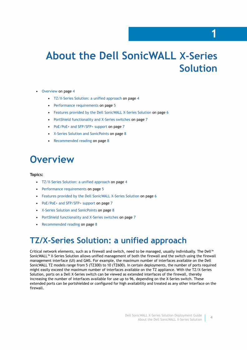
13 Click Next. The Credentials page displays.
14 Change the administration password by entering a new password in the Password and Re-enter Password, fields.
15 Click Next. The Switch Information page displays.
16 Complete the Switch Information and SNMP Settings pages as described in the Dell™ Networking™ X1000 and X4000 Series Switches User Guide.
17 Click Next. The Simple Network Management Protocol (SNMP) Settings page displays.
18 Complete the SNMP Settings page as described in the Dell™ Networking™ X1000 and X4000 Series Switches User Guide.
Dell SonicWALL X-Series Solution Deployment GuideProvisioning an X-Switch on a TZ series appliance
12

19 Click Next. The Summary page displays.
20 Click Finish. The configuration is written in the Startup configuration of the X-switch.
21 Configure the interface as VLAN 1.
22 Ensure the firewall can reach the X-Series switch by pinging the X-Series switch from the firewall before provisioning/managing the switch from the firewall.
Dell SonicWALL X-Series Solution Deployment GuideProvisioning an X-Switch on a TZ series appliance
13

Adding a default gateway through the X-Switch UI
To add a default gateway to a switch through its UI:
1 In the UI, select Switch Management > IPv4 Addressing (or IPv6 Addressing).
The Edit IPv4 Addressings page displays.
Dell SonicWALL X-Series Solution Deployment GuideProvisioning an X-Switch on a TZ series appliance
14

2 Click Add. The Add IPv4 Addressings page displays.
3 Enter the IP address of the default gateway in the Default Gateway field.
4 Click OK.
Provisioning through the CLITopics:
• Provisioning without a default gateway on page 15
• Provisioning with a default gateway on page 16
Provisioning without a default gateway
To provision the X-Series switch on a TZ series firewall without a default gateway:
1 Provision the X-Series switch by performing Step 1 through Step 7 in Provisioning through the X-Series switch user interface on page 9.
2 Enter the following CLI commands:
console#configure terminal console(config)#username admin <password>console(config)#interface vlan 1console(config-if)#ip address 192.168.2.1 255.255.255.0 console(config-if)#endconsole#write memory
NOTE: This is the recommended way.
Dell SonicWALL X-Series Solution Deployment GuideProvisioning an X-Switch on a TZ series appliance
15

3 Ensure the firewall can reach the X-Series switch by pinging the X-Series switch from the firewall before provisioning/managing the switch from the firewall.
Provisioning with a default gateway
To provision the X-Series switch on a TZ series firewall with a default gateway:
1 Provision the X-Series switch by performing Step 1 through Step 7 in Provisioning through the X-Series switch user interface on page 9.
2 Enter the following CLI commands:
console#configure terminalconsole(config)#username admin <password>console(config)#interface vlan 1console(config-if)#ip address 192.168.2.1 255.255.255.0console(config-if)#exitconsole(config)#ip default-gateway 192.168.2.2console(config)#endconsole#write memory
3 Ensure the firewall can reach the X-Series switch by pinging the X-Series switch from the firewall before provisioning/managing the switch from the firewall.
Dell SonicWALL X-Series Solution Deployment GuideProvisioning an X-Switch on a TZ series appliance
16

3
Adding the X-Series switch to SonicOS
• Adding an extended switch on page 17
• Deleting an extended switch on page 19
Adding an extended switch
To add an extended switch:
1 Set up the switch as described in Provisioning an X-Switch on a TZ series appliance on page 9.
2 Ping the switch to ensure the firewall can interact with the switch.
3 Navigate to the Network > PortShield Groups page.
4 Click the External Switch Configuration tab.
5 Click the Add Switch button. The Add External Switch dialog displays.
6 From the ID drop-down menu, select the ID of the switch: 1 (default) or 2.
7 From the Switch Model drop-down menu, select the model of the external switch. The default is X1008.
8 In the IP Address field, enter the IP address of the switch obtained from the label on the switch.
9 In the User Name field, enter the user ID obtained from the label on the switch.
NOTE: To manage the X-Series switch from the firewall, one of the interfaces of the firewall needs to be in the same subnet as the X-Series switch. For example, to manage an X-Series switch with a default IP q, an interface of the firewall needs to be configured in the 192.168.2.0/24 subnet and connected to the X-Series switch.
Dell SonicWALL X-Series Solution Deployment GuideAdding the X-Series switch to SonicOS
17
10 In the Password field, enter either the password obtained from the label on the switch or the one you gave when installing the switch.
11 In the Confirm Password field, enter the password a second time.
12 From the Switch Management drop-down menu, select the port on the extended switch to be used for management traffic. The default is 1.
13 From the Firewall Uplink drop-down menu, select the port on the firewall to be used as the uplink port. The default is None.
14 From the Switch Uplink drop-down menu, select the port on the extended switch to be used as the uplink port. The default is None.
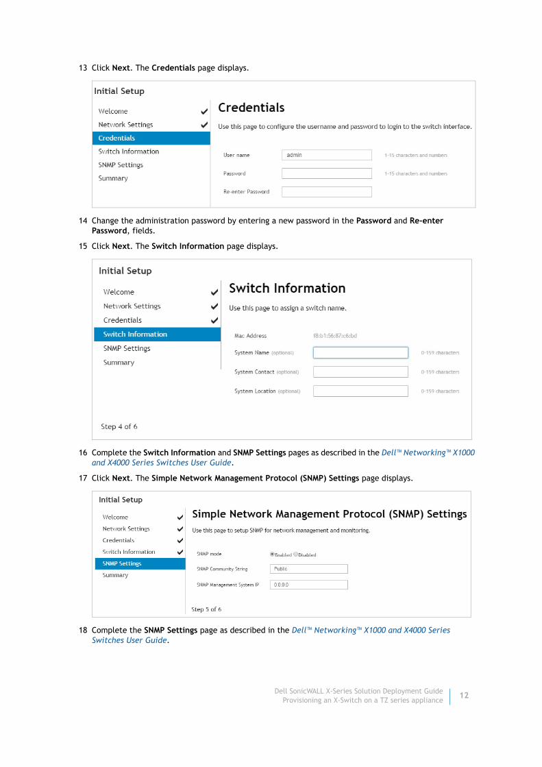
15 Optionally, click the Advanced tab. The options on the tab depend on the extended switch you are adding:
16 From the STP Mode drop-down menu, select:
• Classic
• Rapid (default)
• Multiple
17 From the STP State drop-down menu, select:
• Disabled
• Enabled (default)
18 If you are adding an X1008, X1018, X1026, X1052, or X4012 switch, go to Step 22.
19 In the PoE Alert Usage Threshold field, enter the percentage of power consumed before a trap is generated. The range is 1 to 99, with a default of 95.
20 From the PoE Traps drop-down menu, select whether PoE traps are enabled:
• Disabled (default)
• Enabled
If this option is enabled when the power usage is above the defined threshold in PoE Alert Usage Threshold, traps are generated in situations such as status change or port delivering/not delivering power.
21 From the PoE Power Limit Mode drop-down menu, select how the power to the port is determined:
• Port limit (default) – The power limit of the port depends on the port configuration.
• Class limit – Each port can get up to the maximum power.
TIP: For how to configure the Switch Management, Firewall Uplink, and Switch Uplink options, see the subsection for your topology in Configuring the X-Series Solution in various topologies on page 20.
X1008, X1018, X1026, X1052, X4012 X1008P, X1018P, X1026P, X1052P
Dell SonicWALL X-Series Solution Deployment GuideAdding the X-Series switch to SonicOS
18

22 Click Add.
Deleting an extended switchTo delete an extended switch:
1 Click the Delete icon.
Dell SonicWALL X-Series Solution Deployment GuideAdding the X-Series switch to SonicOS
19

4
Configuring the X-Series Solution in various topologies
• About topologies on page 20
• About links on page 21
• Connecting the X-Series switch management port to a TZ firewall on page 21
• Configuring the different topologies on page 22
• Configuring a common uplink on page 22
• Configuring a dedicated uplink on page 25
• Configuring a hybrid system with common and dedicated uplink(s) on page 31
• Configuring isolated links for management and data uplinks on page 32
• Configuring HA and PortShield with dedicated uplink(s) on page 35
• Configuring VLAN(s) with dedicated uplink(s) on page 37
• Configuring a dedicated link for SonicPoint access on page 42
About topologiesThe key supported topologies for the TZ/X-Series Solution are:
• Common uplink configuration
• Dedicated uplink configuration
• Hybrid configuration with common and dedicated uplink(s)
• Isolated links configuration for management and data traffic
• HA and PortShield configurations with dedicated uplink(s)
• VLAN(s) with dedicated uplink(s) configuration
• SonicPoints with dedicated uplink configuration
IMPORTANT: Before setting up the interface between the TZ appliance and the X-Series switch, set up the switch as described in Provisioning an X-Switch on a TZ series appliance on page 9.
IMPORTANT: When an extended switch has been powered off and then the firewall is restarted (rebooted), it may take up to 5 minutes before the firewall discovers the extended switch and reports the Status of the switch as Connected.
When configuring extended switches in a PortShield group, it may take up to 5 minutes for the configura-tion to be displayed on the Network > PortShield Groups page.
Dell SonicWALL X-Series Solution Deployment GuideConfiguring the X-Series Solution in various topologies
20

Topics:
• About links on page 21
About linksA common link carries data and management traffic. Common links carry all PortShield traffic and all the PortShield groups.
A dedicated link can carry only one PortShield group, and that group must be portshielded to the dedicated port on the TZ appliance.
An isolated link can carry management traffic OR data traffic, but not both at the same time. Isolated links usually have separate connections between the firewall and the X-Switch for management traffic and data traffic.
About uplink interfacesUplink interfaces can be viewed as “trunk” ports set up to carry tagged/untagged traffic. When an extended switch is added with firewall uplink and X-Switch uplink options, the port on the firewall configured as the firewall uplink and the port on the extended switch configured as the switch uplink are set up automatically to receive/send tagged traffic for all IDV VLANs. The IDV VLAN of the tagged traffic allows the firmware to derive the PortShield host interface for the traffic.
Criteria for configuring an uplink interface• The interface should be a physical interface; virtual interfaces are not allowed.
• The interface should be a switch interface. (On some platforms, some firewall interfaces are not connected to the switch. Such interfaces are not allowed.)
• The interface cannot be a PortShield host (some other firewall interface cannot be portshielded to it) or a PortShield group member (cannot be portshielded to another firewall interface).
• The interface cannot be a bridge primary or bridge secondary interface.
• The interface cannot have any children (it cannot be a parent interface for other child interfaces).
Connecting the X-Series switch management port to a TZ firewallThe interface connected to the management port of the X-Switch must have an IP address from the same subnet as the switch. For example, if the management connection between the switch and the TZ is through X2, then X2 must have an IP address from the same subnet, such as 192.168.2.1/24.
Dell SonicWALL X-Series Solution Deployment GuideConfiguring the X-Series Solution in various topologies
21

Configuring the different topologies
Topics:
• Configuring a common uplink on page 22
• Configuring a dedicated uplink on page 25
• Configuring a hybrid system with common and dedicated uplink(s) on page 31
• Configuring isolated links for management and data uplinks on page 32
• Configuring HA and PortShield with dedicated uplink(s) on page 35
• Configuring VLAN(s) with dedicated uplink(s) on page 37
• Configuring a dedicated link for SonicPoint access on page 42
Configuring a common uplink This configuration allows a single link between the firewall and the X-Series switch to be designated as the uplink that carries all PortShield traffic. Both the firewall and switch ports are configured as trunk ports for carrying tagged traffic for VLANs corresponding to all the firewall interfaces. The VLAN tag of the traffic is used to associate the traffic to the PortShield group to which it belongs.
Figure 1 shows a typical integration topology of a TZ500 firewall with an X1026P switch:
• The firewall uplink interface is X3.
• The X-Series switch uplink interface is 2.
This uplink between X3 on the firewall and port 2 on the extended switch is an common link set up to carry PortShield traffic between H1 and H3 and H2 and H4. The uplink is also the one on which the X-Series switch is managed by the firewall. In such a configuration, X3 is configured in the same subnet as the IP of the X-Series switch. Also, X3 is configured as the firewall uplink, and port 2 is configured as the switch management as well as the switch uplink when a switch is provisioned.
Figure 1. Common uplink topology
NOTE: For a complete description of creating PortShield groups, see the SonicOS 6.2 Administration Guide and Adding the X-Series switch to SonicOS on page 17. The following sections describe only those steps required for the various topologies.
NOTE: If necessary, you may choose to have different links carry the PortShield traffic and management traffic. For more information, see Configuring isolated links for management and data uplinks on page 32.
Dell SonicWALL X-Series Solution Deployment GuideConfiguring the X-Series Solution in various topologies
22
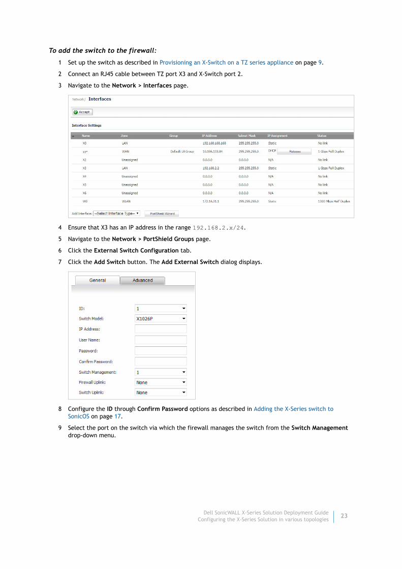
To add the switch to the firewall:
1 Set up the switch as described in Provisioning an X-Switch on a TZ series appliance on page 9.
2 Connect an RJ45 cable between TZ port X3 and X-Switch port 2.
3 Navigate to the Network > Interfaces page.
4 Ensure that X3 has an IP address in the range 192.168.2.x/24.
5 Navigate to the Network > PortShield Groups page.
6 Click the External Switch Configuration tab.
7 Click the Add Switch button. The Add External Switch dialog displays.
8 Configure the ID through Confirm Password options as described in Adding the X-Series switch to SonicOS on page 17.
9 Select the port on the switch via which the firewall manages the switch from the Switch Management drop-down menu.
Dell SonicWALL X-Series Solution Deployment GuideConfiguring the X-Series Solution in various topologies
23

10 Select the Firewall Uplink and Switch Uplink options from their respective drop-down menus.
11 For information about configuring the Advanced tab, see Adding the X-Series switch to SonicOS on page 17.
12 Click Add. The External Switch Configuration tab shows the link between X3 and the X-switch port 2.
• Status – a green Enabled icon
• Switch Management – port 2
• Firewall Uplink – X3
• Switch Uplink – port 2
13 Click the Port Graphics tab.
Dell SonicWALL X-Series Solution Deployment GuideConfiguring the X-Series Solution in various topologies
24

The X3 port and X-Switch 1 port 2 have the same color and small arrow, which means they are the uplink, that is, connected by cable.
14 To PortShield ports on the TZ and X-Switch, see the PortShield sections in the SonicOS 6.2 Administration Guide.
Configuring a dedicated uplinkThis configuration allows a given link between the firewall and the X-Series switch to be designated as the dedicated uplink set up to carry PortShield traffic corresponding to the connected firewall interface. The firewall and switch ports are configured in access mode for the VLAN corresponding to the PortShield VLAN of the firewall interface.
This configuration can be used in deployments where a dedicated 1G link is needed for a particular firewall interface. Cases where this configuration is necessary:
• VLANs are used; for example, another switch behind the X-switch.
• There will be a large volume of traffic and there needs to be a separate uplink for this traffic.
The risk associated with such a configuration is using up interfaces on the firewall fairly soon.
Figure 2 shows a dedicated uplink setup of a TZ500 firewall with an X1026P switch. There are two dedicated uplinks in this scenario:
• The uplink between X3 on the firewall and port 1 on the extended switch is used to manage the switch. In this configuration, X3 is configured in the same subnet as the IP of the X-Series switch.
NOTE: In this example there is no common uplink to carry the PortShield traffic for the rest of the firewall interfaces (excluding X0 and X5 for which dedicated links are set up).
IMPORTANT: For the dedicated uplink to work, the physical link must be connected before being configured.
Dell SonicWALL X-Series Solution Deployment GuideConfiguring the X-Series Solution in various topologies
25

• In addition, there are two dedicated uplinks:
• The uplink between X0 on the firewall and port 11 on the extended switch is a dedicated link to carry all PortShield traffic for X0.
• The uplink between X5 on the firewall and port 7 on the extended switch is a dedicated link to carry all PortShield traffic for X5.
Figure 2. Dedicated uplink topology
You can configure a dedicated uplink with or without setting up the common uplink to carry all PortShield traffic for the different firewall interfaces. In both cases, the common uplink is used to manage the extended switch.
Topics:
• Configuring a dedicated uplink without a common uplink on page 26
• Configuring a dedicated uplink with a common uplink on page 28
Configuring a dedicated uplink without a common uplink
To configure a dedicated uplink topology without an common uplink:
1 Set up the switch as described in Provisioning an X-Switch on a TZ series appliance on page 9.
2 Navigate to the Network > PortShield Groups page.
3 Click the External Switch Configuration tab.
Dell SonicWALL X-Series Solution Deployment GuideConfiguring the X-Series Solution in various topologies
26

4 Click the Edit icon for an unassigned switch. The Edit External Switch dialog displays.
5 Configure the ID through Confirm Password options as described in Adding an extended switch on page 17.
6 Select the port on the switch via which the firewall manages the switch from the Switch Management drop-down menu.
7 To provision the extended switch for a dedicated uplink without a common uplink, ensure the Firewall Uplink and Switch Uplink options are set to None.
8 For information about configuring the Advanced tab, see Adding an extended switch on page 17.
9 Click Add. The dialog closes.
10 Click either the:
• Port Graphics tab.
• Port Configuration tab.
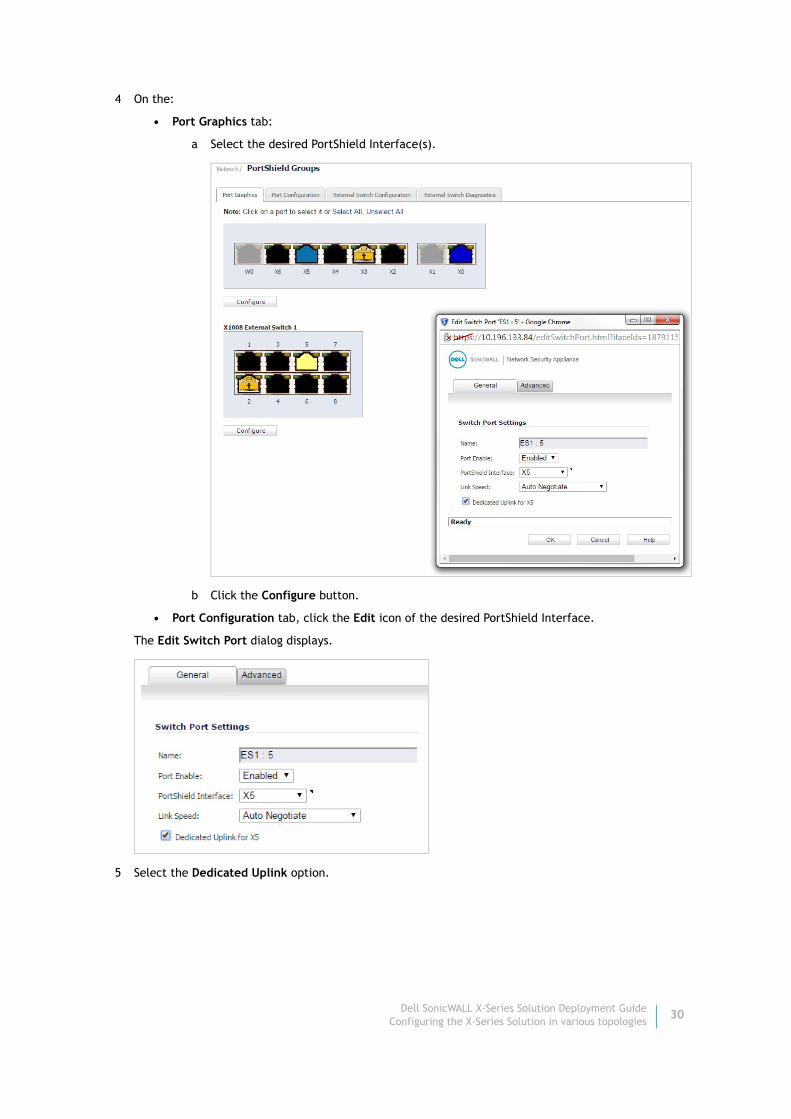
11 On the:
• Port Graphics tab:
a Select the desired PortShield Interface.
b Click the Configure button.
• Port Configuration tab, click the Edit icon of the desired PortShield Interface.
The Edit Switch Port dialog displays.
12 Select the Dedicated Uplink option.
13 Click OK.
Dell SonicWALL X-Series Solution Deployment GuideConfiguring the X-Series Solution in various topologies
27

Configuring a dedicated uplink with a common uplink
To configure a dedicated uplink topology with an common uplink:
1 Provision the switch as described in Provisioning an X-Switch on a TZ series appliance on page 9.
2 Set up the common uplink as described in Adding an extended switch on page 17.
The External Switch Configuration tab is updated.
The External Switch Configuration and Port Graphics tabs are updated.
NOTE: For this example, a cable is connected to TZ port X3 and switch port 2, which has a human icon in the port icon. This connection is a common link because it carries both management and data traffic.
Dell SonicWALL X-Series Solution Deployment GuideConfiguring the X-Series Solution in various topologies
28

On the Port Graphics tab, the icons for TZ port X3 and switch port 2 are the same color and contain an up arrow.
3 Click either the:
• Port Graphics tab.
• Port Configuration tab.
Dell SonicWALL X-Series Solution Deployment GuideConfiguring the X-Series Solution in various topologies
29
4 On the:
• Port Graphics tab:
a Select the desired PortShield Interface(s).
b Click the Configure button.
• Port Configuration tab, click the Edit icon of the desired PortShield Interface.
The Edit Switch Port dialog displays.
5 Select the Dedicated Uplink option.
Dell SonicWALL X-Series Solution Deployment GuideConfiguring the X-Series Solution in various topologies
30
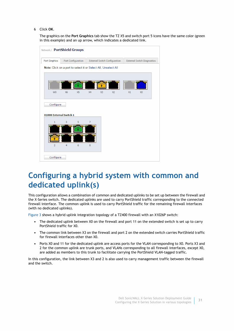
6 Click OK.
The graphics on the Port Graphics tab show the TZ X5 and switch port 5 icons have the same color (green in this example) and an up arrow, which indicates a dedicated link.
Configuring a hybrid system with common and dedicated uplink(s)This configuration allows a combination of common and dedicated uplinks to be set up between the firewall and the X-Series switch. The dedicated uplinks are used to carry PortShield traffic corresponding to the connected firewall interface. The common uplink is used to carry PortShield traffic for the remaining firewall interfaces (with no dedicated uplinks).
Figure 3 shows a hybrid uplink integration topology of a TZ400 firewall with an X1026P switch:
• The dedicated uplink between X0 on the firewall and port 11 on the extended switch is set up to carry PortShield traffic for X0.
• The common link between X3 on the firewall and port 2 on the extended switch carries PortShield traffic for firewall interfaces other than X0.
• Ports X0 and 11 for the dedicated uplink are access ports for the VLAN corresponding to X0. Ports X3 and 2 for the common uplink are trunk ports, and VLANs corresponding to all firewall interfaces, except X0, are added as members to this trunk to facilitate carrying the PortShield VLAN-tagged traffic.
In this configuration, the link between X3 and 2 is also used to carry management traffic between the firewall and the switch.
Dell SonicWALL X-Series Solution Deployment GuideConfiguring the X-Series Solution in various topologies
31
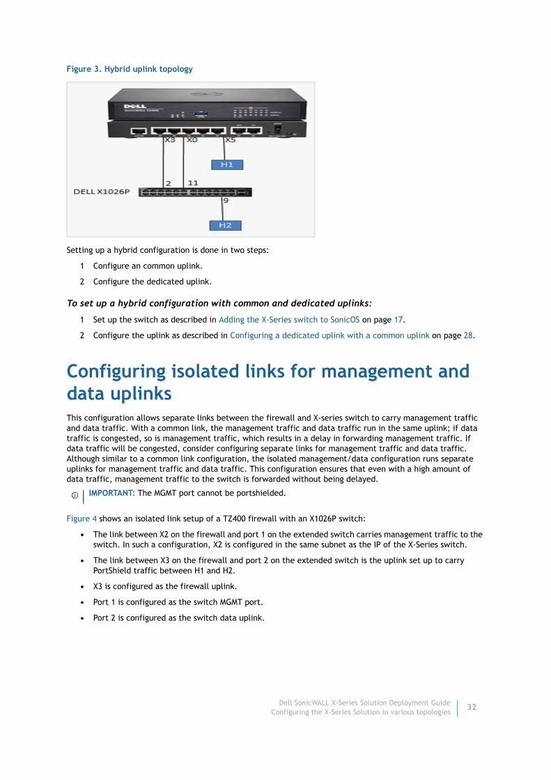
Figure 3. Hybrid uplink topology
Setting up a hybrid configuration is done in two steps:
1 Configure an common uplink.
2 Configure the dedicated uplink.
To set up a hybrid configuration with common and dedicated uplinks:
1 Set up the switch as described in Adding the X-Series switch to SonicOS on page 17.
2 Configure the uplink as described in Configuring a dedicated uplink with a common uplink on page 28.
Configuring isolated links for management and data uplinks This configuration allows separate links between the firewall and X-series switch to carry management traffic and data traffic. With a common link, the management traffic and data traffic run in the same uplink; if data traffic is congested, so is management traffic, which results in a delay in forwarding management traffic. If data traffic will be congested, consider configuring separate links for management traffic and data traffic. Although similar to a common link configuration, the isolated management/data configuration runs separate uplinks for management traffic and data traffic. This configuration ensures that even with a high amount of data traffic, management traffic to the switch is forwarded without being delayed.
Figure 4 shows an isolated link setup of a TZ400 firewall with an X1026P switch:
• The link between X2 on the firewall and port 1 on the extended switch carries management traffic to the switch. In such a configuration, X2 is configured in the same subnet as the IP of the X-Series switch.
• The link between X3 on the firewall and port 2 on the extended switch is the uplink set up to carry PortShield traffic between H1 and H2.
• X3 is configured as the firewall uplink.
• Port 1 is configured as the switch MGMT port.
• Port 2 is configured as the switch data uplink.
IMPORTANT: The MGMT port cannot be portshielded.
Dell SonicWALL X-Series Solution Deployment GuideConfiguring the X-Series Solution in various topologies
32
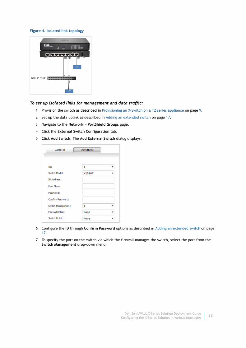
Figure 4. Isolated link topology
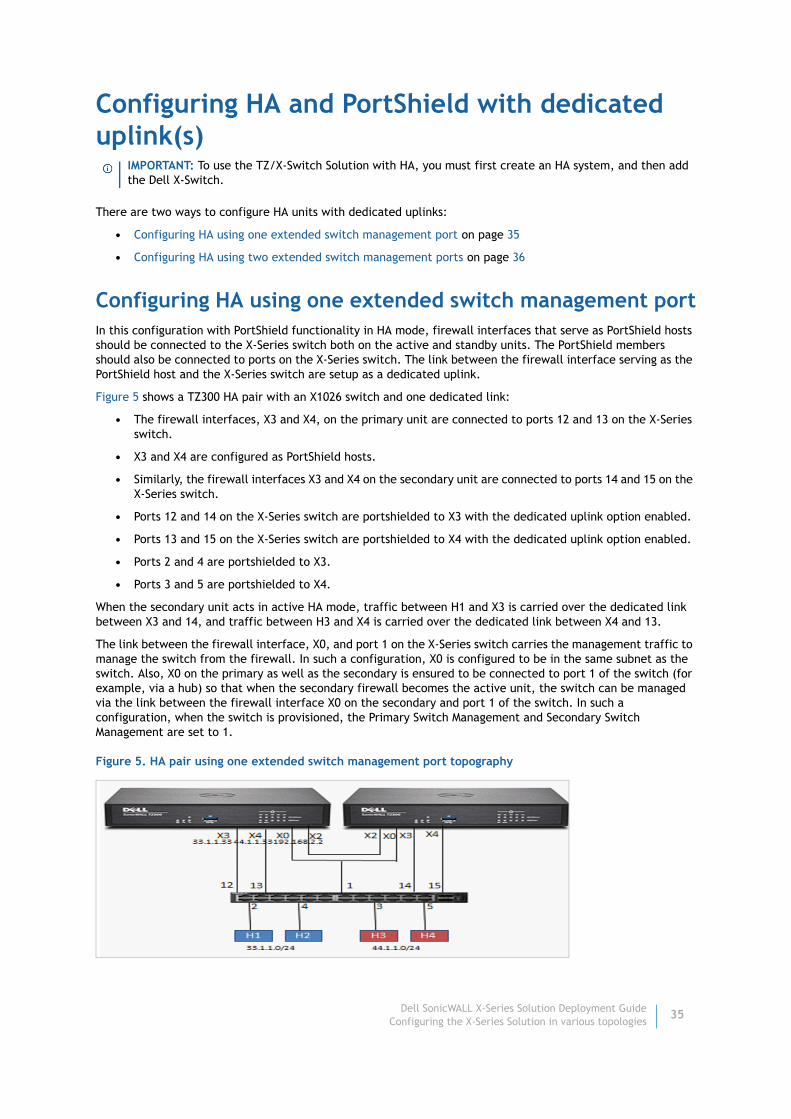
To set up isolated links for management and data traffic:
1 Provision the switch as described in Provisioning an X-Switch on a TZ series appliance on page 9.
2 Set up the data uplink as described in Adding an extended switch on page 17.
3 Navigate to the Network > PortShield Groups page.
4 Click the External Switch Configuration tab.
5 Click Add Switch. The Add External Switch dialog displays.
6 Configure the ID through Confirm Password options as described in Adding an extended switch on page 17.
7 To specify the port on the switch via which the firewall manages the switch, select the port from the Switch Management drop-down menu.
Dell SonicWALL X-Series Solution Deployment GuideConfiguring the X-Series Solution in various topologies
33

8 Select the Firewall Uplink and Switch Uplink options from their respective drop-down menus:
9 Click Add.
The extended switch configuration is displayed on the Network > PortShield Groups > External Switch Configuration tab.
The Port Graphics tab displays:
• The extended switch port 1 is management (it is grey with a human icon in it).
• The data uplink is between X3 and extended port 2.
Dell SonicWALL X-Series Solution Deployment GuideConfiguring the X-Series Solution in various topologies
34
Configuring HA and PortShield with dedicated uplink(s)
There are two ways to configure HA units with dedicated uplinks:
• Configuring HA using one extended switch management port on page 35
• Configuring HA using two extended switch management ports on page 36
Configuring HA using one extended switch management portIn this configuration with PortShield functionality in HA mode, firewall interfaces that serve as PortShield hosts should be connected to the X-Series switch both on the active and standby units. The PortShield members should also be connected to ports on the X-Series switch. The link between the firewall interface serving as the PortShield host and the X-Series switch are setup as a dedicated uplink.
Figure 5 shows a TZ300 HA pair with an X1026 switch and one dedicated link:
• The firewall interfaces, X3 and X4, on the primary unit are connected to ports 12 and 13 on the X-Series switch.
• X3 and X4 are configured as PortShield hosts.
• Similarly, the firewall interfaces X3 and X4 on the secondary unit are connected to ports 14 and 15 on the X-Series switch.
• Ports 12 and 14 on the X-Series switch are portshielded to X3 with the dedicated uplink option enabled.
• Ports 13 and 15 on the X-Series switch are portshielded to X4 with the dedicated uplink option enabled.
• Ports 2 and 4 are portshielded to X3.
• Ports 3 and 5 are portshielded to X4.
When the secondary unit acts in active HA mode, traffic between H1 and X3 is carried over the dedicated link between X3 and 14, and traffic between H3 and X4 is carried over the dedicated link between X4 and 13.
The link between the firewall interface, X0, and port 1 on the X-Series switch carries the management traffic to manage the switch from the firewall. In such a configuration, X0 is configured to be in the same subnet as the switch. Also, X0 on the primary as well as the secondary is ensured to be connected to port 1 of the switch (for example, via a hub) so that when the secondary firewall becomes the active unit, the switch can be managed via the link between the firewall interface X0 on the secondary and port 1 of the switch. In such a configuration, when the switch is provisioned, the Primary Switch Management and Secondary Switch Management are set to 1.
Figure 5. HA pair using one extended switch management port topography
IMPORTANT: To use the TZ/X-Switch Solution with HA, you must first create an HA system, and then add the Dell X-Switch.
Dell SonicWALL X-Series Solution Deployment GuideConfiguring the X-Series Solution in various topologies
35

To set up HA with one dedicated uplink:
1 Provision the switch as described in Provisioning an X-Switch on a TZ series appliance on page 9.
2 Set up the data uplink as described in Adding an extended switch on page 17.
3 Configure the options as described in Configuring a common uplink on page 22 except:
a Select the Primary Switch Management and Secondary Switch Management interfaces from their respective drop-down menus:
4 Click Add.
Configuring HA using two extended switch management portsYou can choose to connect X0 of the primary and secondary directly to the ports on the X-series switch. In this case, two switch ports are used on the X-series for management traffic.
Figure 6 shows a a TZ300 HA pair with an X1026 switch and two dedicated links:
• X0 of the primary unit is connected to port 1.
• X0 of the secondary unit is connected to port 7
When the switch is provisioned, the primary switch management is set to 1 and the secondary switch management is set to 7. When the primary firewall is active, the link between X0 of the primary and port 1 of the switch carry the management traffic. When the secondary firewall is active, the link between X0 of the secondary and port 7 of the switch is used by the firewall to manage the switch.
NOTE: The Firewall Uplink and Switch Uplink options are not relevant for a firewall operating in HA mode.
Dell SonicWALL X-Series Solution Deployment GuideConfiguring the X-Series Solution in various topologies
36

Figure 6. HA pair using two extended switch management ports topography
To set up HA with one dedicated uplink:
1 Provision the switch as described in Provisioning an X-Switch on a TZ series appliance on page 9.
2 Set up the data uplink as described in Adding an extended switch on page 17.
3 Configure the options as described in Configuring a common uplink on page 22 except:
a Select the Primary Switch Management and Primary Switch Management interfaces from their respective drop-down menus:
4 Click Add.
Configuring VLAN(s) with dedicated uplink(s)For more information about X-Series Solution support for VLAN, see Dell SonicWALL X_Series Solution - Support for SonicWALL Virtual Interfaces (VLANs) (189771).
Topics:
• Prerequisites for VLAN support on page 38
• Configuring a dedicated uplink for VLANs on page 38
NOTE: The Firewall Uplink and Switch Uplink options are not relevant for a firewall operating in HA mode.
Dell SonicWALL X-Series Solution Deployment GuideConfiguring the X-Series Solution in various topologies
37

• Configuring a dedicated uplink plus a common uplink for VLANs on page 41
Prerequisites for VLAN support• Support for VLANs is available only on dedicated uplinks. Support for VLANs is not available on common
uplinks. For example, VLANs cannot be configured under the firewall interface provisioned as the common uplink for the X-Series switch.
• Overlapping VLANs cannot exist under appliance interfaces configured as dedicated uplinks. For example, if X3 and X5 are configured for dedicated uplinks, VLAN 100 cannot be present under both X3 and X5. Such a configuration is rejected.
Configuring a dedicated uplink for VLANs
Topics:
• Dedicated Uplink for VLAN Topology on page 38
• Configuring a Dedicated Uplink for a VLAN on page 39
Dedicated Uplink for VLAN Topology
In a dedicated uplink configuration, a given link between the firewall and the X-Series switch designated as the dedicated uplink is set up to carry traffic for all VLANs configured under the firewall interface plus PortShield traffic corresponding to the firewall interface.
Figure 7 shows a TZ500 with an X1026P switch:
Figure 7. VLAN with dedicated uplink topology
• The link between X3 and port 1 on the extended switch is used by the firewall to manage the switch.
• Interface X3 is configured to be in the same subnet as the IP of the switch.
• There are three VLAN interfaces with VLAN tags 100, 150, and 200 configured under X5.
• The link between X5 on the firewall and port 3 on the extended switch is a dedicated link set up to carry traffic tagged with VLANs 100, 150, and 200 and untagged traffic for X5.
NOTE: In this example, a common uplink is not required, hence, the extended switch is provisioned with the Firewall Uplink and Switch Uplink options set to None and Switch Management set to 1.
Dell SonicWALL X-Series Solution Deployment GuideConfiguring the X-Series Solution in various topologies
38
Supporting such a topology, requires this configuration:
• Port 3 is portshielded to X5 with dedicated uplink option.
• Port 10 is portshielded to X5 and configured as a trunk to carry VLAN 100.
• Port 11 is portshielded to X5 and configured as a trunk to carry VLAN 150.
• Port 12 is portshielded to X5 and configured as an access to carry VLAN 200.
Configuring a Dedicated Uplink for a VLAN
Support for VLAN(s) can be achieved in a multi-step configuration process:
1 Provision the switch. The switch can be provisioned with the:
• Firewall uplink and switch uplink set to None if support for VLAN(s) alone is needed.
• Common uplink option if support is needed for an common trunk interface to carry PortShield traffic for other firewall interfaces along with VLAN(s) support.
2 Configure the dedicated link by:
a Choosing an extended switch port that is connected physically to the firewall interface.
b Portshielding the port to the firewall interface.
c Choosing the dedicated link option.
3 Select the extended switch port on which VLAN(s) need to be enabled
4 Portshield the switch port to the firewall interface.
5 Configure the required VLAN(s) under the VLAN tab.
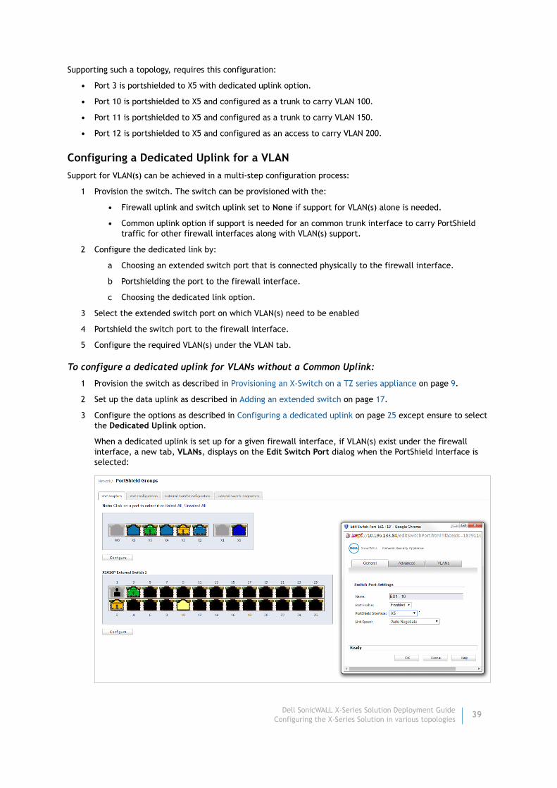
To configure a dedicated uplink for VLANs without a Common Uplink:
1 Provision the switch as described in Provisioning an X-Switch on a TZ series appliance on page 9.
2 Set up the data uplink as described in Adding an extended switch on page 17.
3 Configure the options as described in Configuring a dedicated uplink on page 25 except ensure to select the Dedicated Uplink option.
When a dedicated uplink is set up for a given firewall interface, if VLAN(s) exist under the firewall interface, a new tab, VLANs, displays on the Edit Switch Port dialog when the PortShield Interface is selected:
Dell SonicWALL X-Series Solution Deployment GuideConfiguring the X-Series Solution in various topologies
39

4 Use the VLANs tab to configure an extended switch port in trunk or access mode. In this example, Port 10 is portshielded to X5 and configured as a trunk to carry VLAN 100 by selecting Enabled for the VLAN Trunk option and choosing VLAN 100 from the available list of VLANs:
5 Similarly, Port 11 is portshielded to X5 and configured as a trunk to carry VLAN 150 by:
a Selecting Enabled for the VLAN Trunk option.
b Choosing VLAN 150 from the available list of VLANs.
6 Portshield port 12 to X5 and configure it as an access for VLAN 200 by:
a Selecting Disabled for the VLAN Trunk option.
Dell SonicWALL X-Series Solution Deployment GuideConfiguring the X-Series Solution in various topologies
40
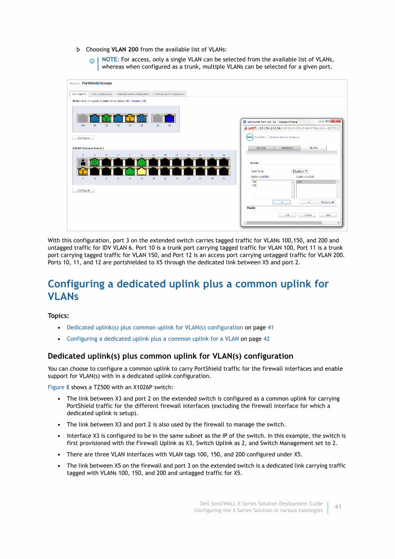
b Choosing VLAN 200 from the available list of VLANs:
With this configuration, port 3 on the extended switch carries tagged traffic for VLANs 100,150, and 200 and untagged traffic for IDV VLAN 6. Port 10 is a trunk port carrying tagged traffic for VLAN 100, Port 11 is a trunk port carrying tagged traffic for VLAN 150, and Port 12 is an access port carrying untagged traffic for VLAN 200. Ports 10, 11, and 12 are portshielded to X5 through the dedicated link between X5 and port 2.
Configuring a dedicated uplink plus a common uplink for VLANs
Topics:
• Dedicated uplink(s) plus common uplink for VLAN(s) configuration on page 41
• Configuring a dedicated uplink plus a common uplink for a VLAN on page 42
Dedicated uplink(s) plus common uplink for VLAN(s) configuration
You can choose to configure a common uplink to carry PortShield traffic for the firewall interfaces and enable support for VLAN(s) with in a dedicated uplink configuration.
Figure 8 shows a TZ500 with an X1026P switch:
• The link between X3 and port 2 on the extended switch is configured as a common uplink for carrying PortShield traffic for the different firewall interfaces (excluding the firewall interface for which a dedicated uplink is setup).
• The link between X3 and port 2 is also used by the firewall to manage the switch.
• Interface X3 is configured to be in the same subnet as the IP of the switch. In this example, the switch is first provisioned with the Firewall Uplink as X3, Switch Uplink as 2, and Switch Management set to 2.
• There are three VLAN interfaces with VLAN tags 100, 150, and 200 configured under X5.
• The link between X5 on the firewall and port 3 on the extended switch is a dedicated link carrying traffic tagged with VLANs 100, 150, and 200 and untagged traffic for X5.
NOTE: For access, only a single VLAN can be selected from the available list of VLANs, whereas when configured as a trunk, multiple VLANs can be selected for a given port.
Dell SonicWALL X-Series Solution Deployment GuideConfiguring the X-Series Solution in various topologies
41

Supporting such a topology, requires this configuration:
• Port 3 is portshielded to X5 with dedicated uplink option.
• Port 10 is portshielded to X5 and configured as a trunk to carry VLAN 100.
• Port 11 is portshielded to X5 and configured as a trunk to carry VLAN 150.
• Port 12 is portshielded to X5 and configured as an access to carry VLAN 200
Figure 8. VLAN(s) with dedicated uplink(s) plus common uplink topography
Configuring a dedicated uplink plus a common uplink for a VLAN
To configure a dedicated uplink plus a common uplink for a VLAN:
1 Provision the switch as described in Provisioning an X-Switch on a TZ series appliance on page 9.
2 Set up the data uplink as described in Adding an extended switch on page 17.
3 Configure the uplinks as described in Configuring a dedicated uplink for VLANs on page 38.
Configuring a dedicated link for SonicPoint access It is recommended that SonicPoint access points be connected through dedicated links because SonicPoint access points carry several VLANS, and dedicated links pass through VLAN tunnels. The dedicated links act as trunks passing tagged traffic from the access point through the X-Series switch to the TZ firewall.
For non-SonicPoint access points and for SonicPoints without particular management, the port in the TZ firewall can be configured as ANY (LAN/WAN/DMZ, although usually LAN). In this case, the pair of ports between the TZ firewall and the X-Series switch must be configured as a dedicated link. Other ports on the X-Series switch that are expected to connect to access points with RJ45 are portshielded to that dedicated port.
If the SonicPoint access points are behind the TZ firewall and are to be managed, the pair ports on the firewall and the X-Series switch must be configured as a dedicated link. The dedicated port on the firewall must be configured as WLAN. Other ports on the X-Series switch that are expected to connect to SonicPoint access points with RJ45 are portshielded to that dedicated port.
IMPORTANT: Any SonicPoint with an external power source (AC power supply or power adapter) can be portshielded to any Ethernet port.
Dell SonicWALL X-Series Solution Deployment GuideConfiguring the X-Series Solution in various topologies
42

When SonicPoints are configured with X-Series switches, the SonicPoints must be portshielded in a group configured to a port of the dedicated link. See Figure 9.
Figure 9. SonicPoints and a dedicated uplink
For more information about using SonicPoints with an X-Series switch, see Dell SonicWALL TZ Series and Dell SonicWALL X-Series solution managing SonicPoint ACe/ACi/N2 access points (SW13970).
To configure a dedicated uplink for SonicPoints:
1 Provision the switch as described in Provisioning an X-Switch on a TZ series appliance on page 9.
2 Set up the data uplink as described in Adding an extended switch on page 17.
3 Configure the uplinks as described in Configuring a dedicated uplink for VLANs on page 38.
4 Ensure that all SonicPoints are connected to X-Switch ports configured in the PortShield group of the dedicated link.
Dell SonicWALL X-Series Solution Deployment GuideConfiguring the X-Series Solution in various topologies
43
About Dell
Dell listens to customers and delivers worldwide innovative technology, business solutions and services they trust and value. For more information, visit www.software.dell.com.
Contacting DellFor sales or other inquiries, visit http://software.dell.com/company/contact-us.aspx or call 1-949-754-8000.
Technical support resourcesTechnical support is available to customers who have purchased Dell software with a valid maintenance contract and to customers who have trial versions. To access the Support Portal, go to https://support.software.dell.com/.
The Support Portal provides self-help tools you can use to solve problems quickly and independently, 24 hours a day, 365 days a year. In addition, the portal provides direct access to product support engineers through an online Service Request system.
The site enables you to:
• Create, update, and manage Service Requests (cases)
• View Knowledge Base articles
• Obtain product notifications
• Download software. For trial software, go to http://software.dell.com/trials.
• View how-to videos
• Engage in community discussions
• Chat with a support engineer
Dell SonicWALL X-Series Solution Deployment GuideAbout Dell
44

Index
Dell SonicWALL X-Series Solution Deployment GuideIndex
45
Bbutton
Managed Mode, 10
Ccommon link, 21
Ddedicated link, 21
Eextended switch
global parameters, 6overview, 4supported topologies, 20TZ series appliances, 5
Iinterface
uplink, 21isolated link, 21
Llink
common, 21dedicated, 21isolated, 21
MManaged Mode button, 10
PPoE (Power over Ethernet), 5PoE+ (Power over Ethernet Plus), 5
Sswitch, extended
See extended switch, 4
Uuplink
common configuration, 22extended switch, 21firewall, 21interface, 21X-Switch, 21
uplink interfacecriteria for configuring, 21
Index