delmia process engineer
TRANSCRIPT
PR
OC
ES
S P
LAN
NIN
G
DELMIAProcess EngineerA Process Driven Approach to Process and Resource Planning
2
DELMIA Process EngineerToday's enterprises must continuallyincrease their productivity in order tocompete effectively. This requires shorterdelivery times, reduced operating costs,optimal utilization of capacities andoptimized material and information flow.
At the same time, total automation, definedpreviously as the ultimate goal, is beingsuperseded by hybrid, partially automatedand therefore flexible production systems.Against the background of competition andworkplace safety, more attention must bepaid to the people at the workplace - acompany's most important capital. In many
cases, cost pressures and overburdenedwork planning departments lead to poorlydesigned workplaces. This, in turn, results inpoor work performance and low job satisfac-tion. More than ever before, industrialenterprises need planning tools with whichmanual and partially automated workplacescan be designed quickly, cost-effectively,reliably and ergonomically.
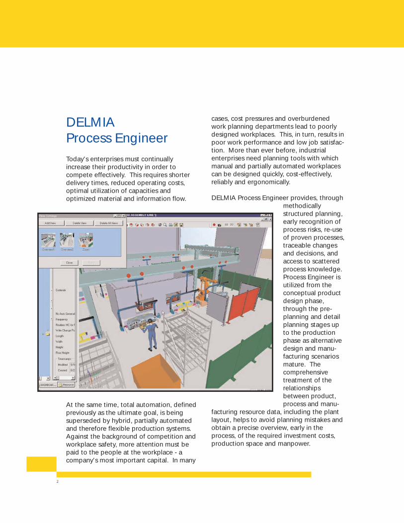
DELMIA Process Engineer provides, throughmethodicallystructured planning,early recognition ofprocess risks, re-useof proven processes,traceable changesand decisions, andaccess to scatteredprocess knowledge.Process Engineer isutilized from theconceptual productdesign phase,through the pre-planning and detailplanning stages upto the productionphase as alternativedesign and manu-facturing scenariosmature. Thecomprehensivetreatment of therelationshipsbetween product,process and manu-
facturing resource data, including the plantlayout, helps to avoid planning mistakes andobtain a precise overview, early in theprocess, of the required investment costs,production space and manpower.
3
Benefits AchievedUsing Process Engineer
• Optimization of Material Flow
• Reduction of Standard Times
• Modular Product Concept
• Design for Manufacturing
• Fast Product Development
• Short Main Line Concept
• Efficient Logistics• High Production
Flexibility• Quality Improvement• Simultaneous
Engineering
Results: Savings / Benefits
• Reduction of Workstations• Decreased Work-In-Progress Inventory• Shortening of Lead Time• Reduction of Floor Space• Reduction of Capital and Operating Costs
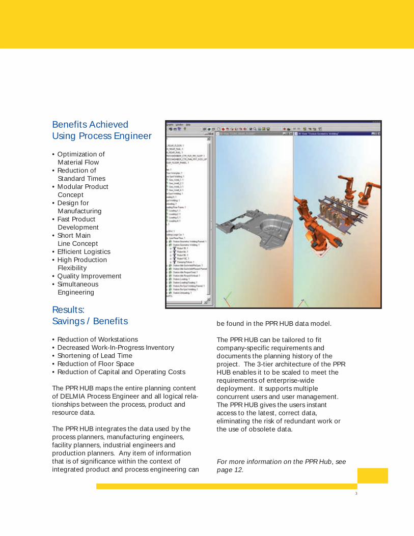
The PPR HUB maps the entire planning contentof DELMIA Process Engineer and all logical rela-tionships between the process, product andresource data.
The PPR HUB integrates the data used by theprocess planners, manufacturing engineers,facility planners, industrial engineers andproduction planners. Any item of informationthat is of significance within the context ofintegrated product and process engineering can
be found in the PPR HUB data model.
The PPR HUB can be tailored to fitcompany-specific requirements anddocuments the planning history of theproject. The 3-tier architecture of the PPRHUB enables it to be scaled to meet therequirements of enterprise-widedeployment. It supports multipleconcurrent users and user management.The PPR HUB gives the users instantaccess to the latest, correct data,eliminating the risk of redundant work orthe use of obsolete data.
For more information on the PPR Hub, seepage 12.
4
DELMIA Process EngineerMeets Your Requirements forProcess Planning
• Provides a structured methodology that systematically leads to an optimal solution by considering all process-related costs and analyzing alternatives early in the planning stage.
• Presents a clear view of the overall system performance versus target values during all planning phases.
• Reduces risks by the re-use of proven processes.
• Supports multiple users, shortening planning time.
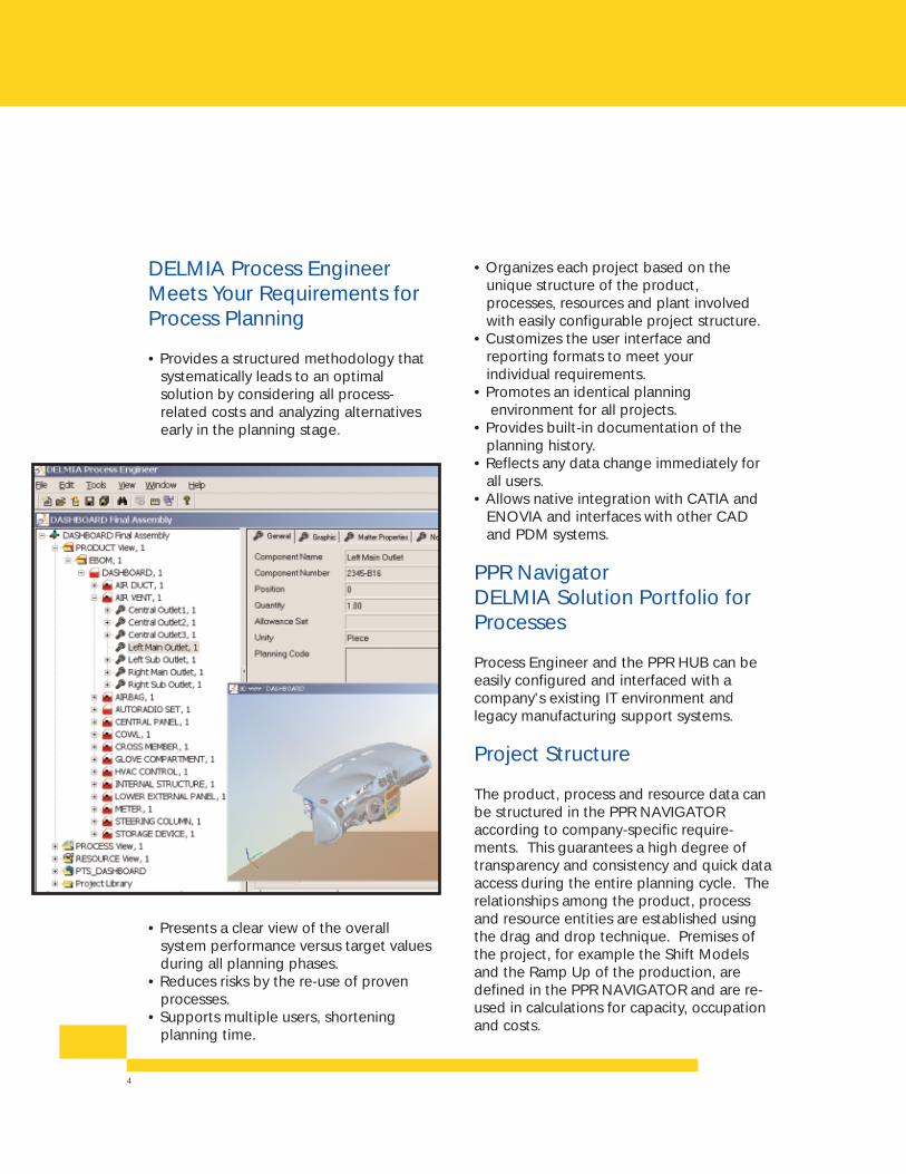
• Organizes each project based on the unique structure of the product, processes, resources and plant involved with easily configurable project structure.
• Customizes the user interface and reporting formats to meet your individual requirements.
• Promotes an identical planning environment for all projects.
• Provides built-in documentation of the planning history.
• Reflects any data change immediately for all users.
• Allows native integration with CATIA and ENOVIA and interfaces with other CAD and PDM systems.
PPR NavigatorDELMIA Solution Portfolio forProcesses
Process Engineer and the PPR HUB can beeasily configured and interfaced with acompany's existing IT environment andlegacy manufacturing support systems.
Project Structure
The product, process and resource data canbe structured in the PPR NAVIGATORaccording to company-specific require-ments. This guarantees a high degree oftransparency and consistency and quick dataaccess during the entire planning cycle. Therelationships among the product, processand resource entities are established usingthe drag and drop technique. Premises ofthe project, for example the Shift Modelsand the Ramp Up of the production, aredefined in the PPR NAVIGATOR and are re-used in calculations for capacity, occupationand costs.
5
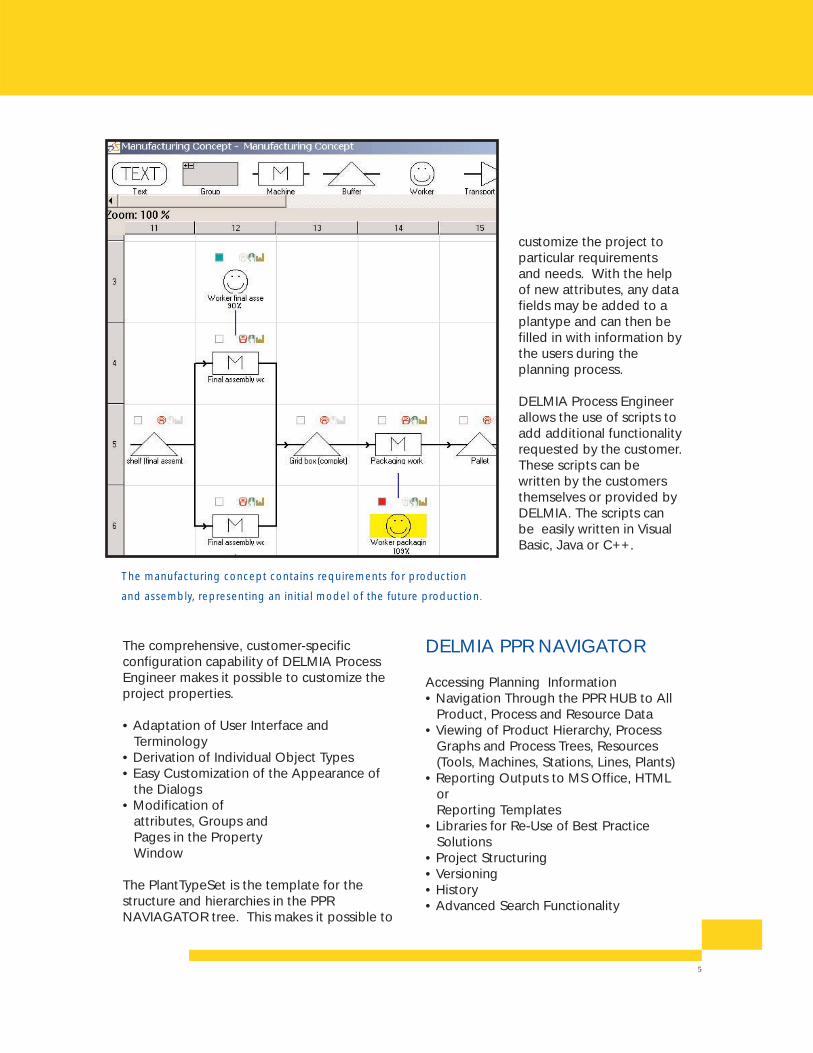
The manufacturing concept contains requirements for production
and assembly, representing an initial model of the future production.
The comprehensive, customer-specificconfiguration capability of DELMIA ProcessEngineer makes it possible to customize theproject properties.
• Adaptation of User Interface and Terminology
• Derivation of Individual Object Types• Easy Customization of the Appearance of
the Dialogs• Modification of
attributes, Groups and Pages in the Property Window
The PlantTypeSet is the template for thestructure and hierarchies in the PPRNAVIAGATOR tree. This makes it possible to
customize the project toparticular requirementsand needs. With the helpof new attributes, any datafields may be added to aplantype and can then befilled in with information bythe users during theplanning process.
DELMIA Process Engineer allows the use of scripts to add additional functionality requested by the customer.These scripts can bewritten by the customersthemselves or provided by DELMIA. The scripts canbe easily written in Visual Basic, Java or C++.
DELMIA PPR NAVIGATOR
Accessing Planning Information• Navigation Through the PPR HUB to All
Product, Process and Resource Data• Viewing of Product Hierarchy, Process
Graphs and Process Trees, Resources (Tools, Machines, Stations, Lines, Plants)
• Reporting Outputs to MS Office, HTML or Reporting Templates
• Libraries for Re-Use of Best Practice Solutions
• Project Structuring• Versioning• History• Advanced Search Functionality
6
Process Engineer Begins withthe EBOM and Ends withAchieving Your ProductionTargets
DELMIA Process Engineer builds uponexisting CAD data and PDM systems through powerful, flexible and configurableinterfaces. The integrations to PDMsystems are established by the high-performance DELMIA PPR LOADER (Partof DS PPR GATEWAY) so bills of materialsand product structures are imported andsynchronized directly. It allows specialstructures and attributes of various PDMsystems to be interpreted and makes themavailable to the PPR HUB in the desiredform. Any 3D CAD model required isimported from the CAD system. DELMIAProcess Engineer can examine theplanning context from the point of view ofany object type, i.e., product, process orresource. All associated data can beaccessed. For example, production
processes and equipment used,costs, dimensions, volumes andmarginal planning conditions maybe directly queried from theproduct structure. Special organiza-tional views set up for the desiredtype of plan at the enterprise orproject level are also available, forexample, the "Brake Systems" viewin the product structure.
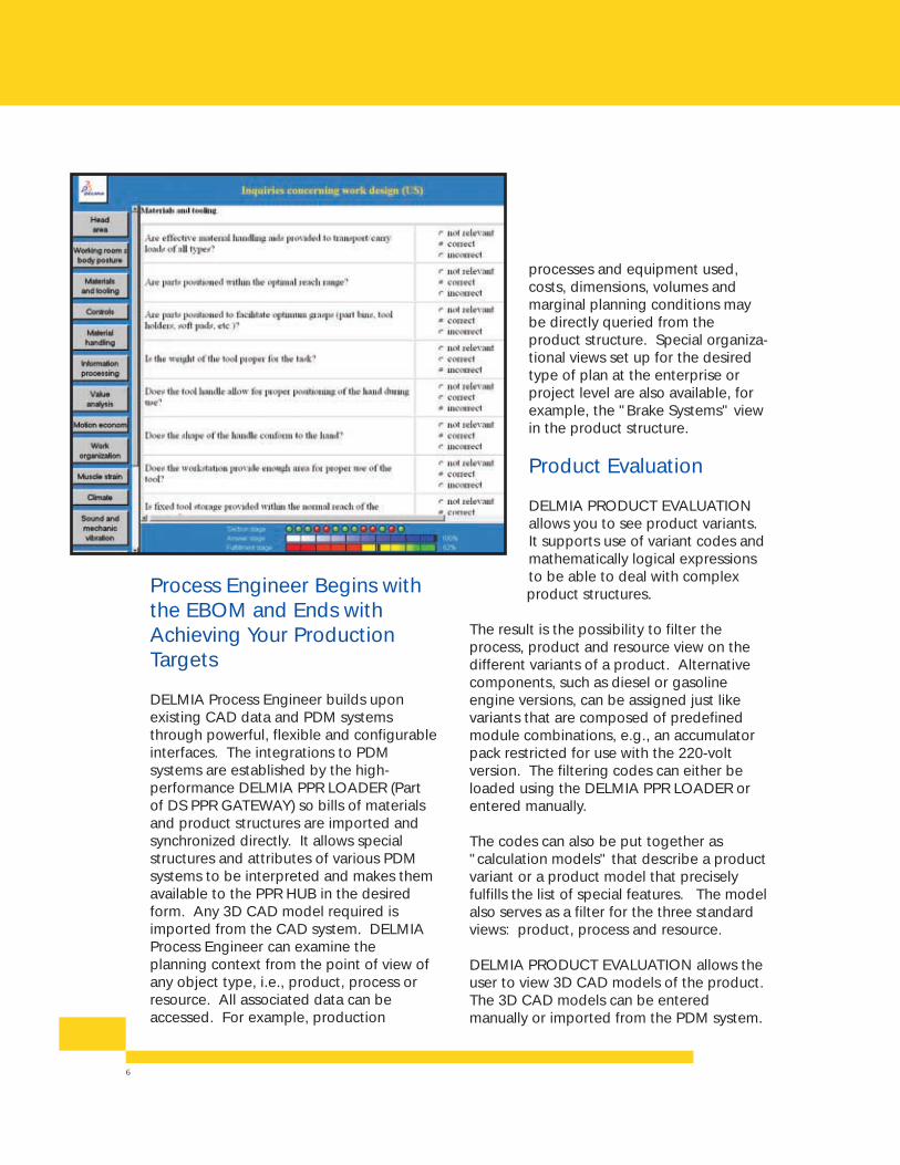
Product Evaluation
DELMIA PRODUCT EVALUATIONallows you to see product variants.It supports use of variant codes andmathematically logical expressionsto be able to deal with complex product structures.
The result is the possibility to filter theprocess, product and resource view on thedifferent variants of a product. Alternativecomponents, such as diesel or gasolineengine versions, can be assigned just likevariants that are composed of predefinedmodule combinations, e.g., an accumulatorpack restricted for use with the 220-voltversion. The filtering codes can either beloaded using the DELMIA PPR LOADER orentered manually.
The codes can also be put together as"calculation models" that describe a productvariant or a product model that preciselyfulfills the list of special features. The modelalso serves as a filter for the three standardviews: product, process and resource.
DELMIA PRODUCT EVALUATION allows theuser to view 3D CAD models of the product.The 3D CAD models can be enteredmanually or imported from the PDM system.
7
Process & Resource PlanningProcess Graph
In the Process Graph, shown as a precedencegraph, the modules and assembly steps ofthe product are outlined. This first and stillvery coarse model of future manufacturing isneutral with regard to the solutions availableand typically takes into account only value-adding processes those that are defined asindispensable for the product specifications.The processes are interlinked in a simple andintuitive manner as predecessors, successorsand parallels and result in a processsequence. The processes can either bestructured hierarchically or combined ingroups. This enables a top-down planning,where a rough overview is created, to bedetailed later. The displaying of theprocesses as a graphic view makes theprocess flow easy to understand andcommunicate.
The Process Graph can comprise process-related information in classifying attributesthat are completely configurable. Estimatedprocess times can be entered and later
updated to precise analyses and FMEA-compatible risk analysis can be applied.Assemblies and parts from the productstructure can be assigned to the processesby dragging and dropping. Provenprocedures can be stored in a processlibrary for retrieval in planning.
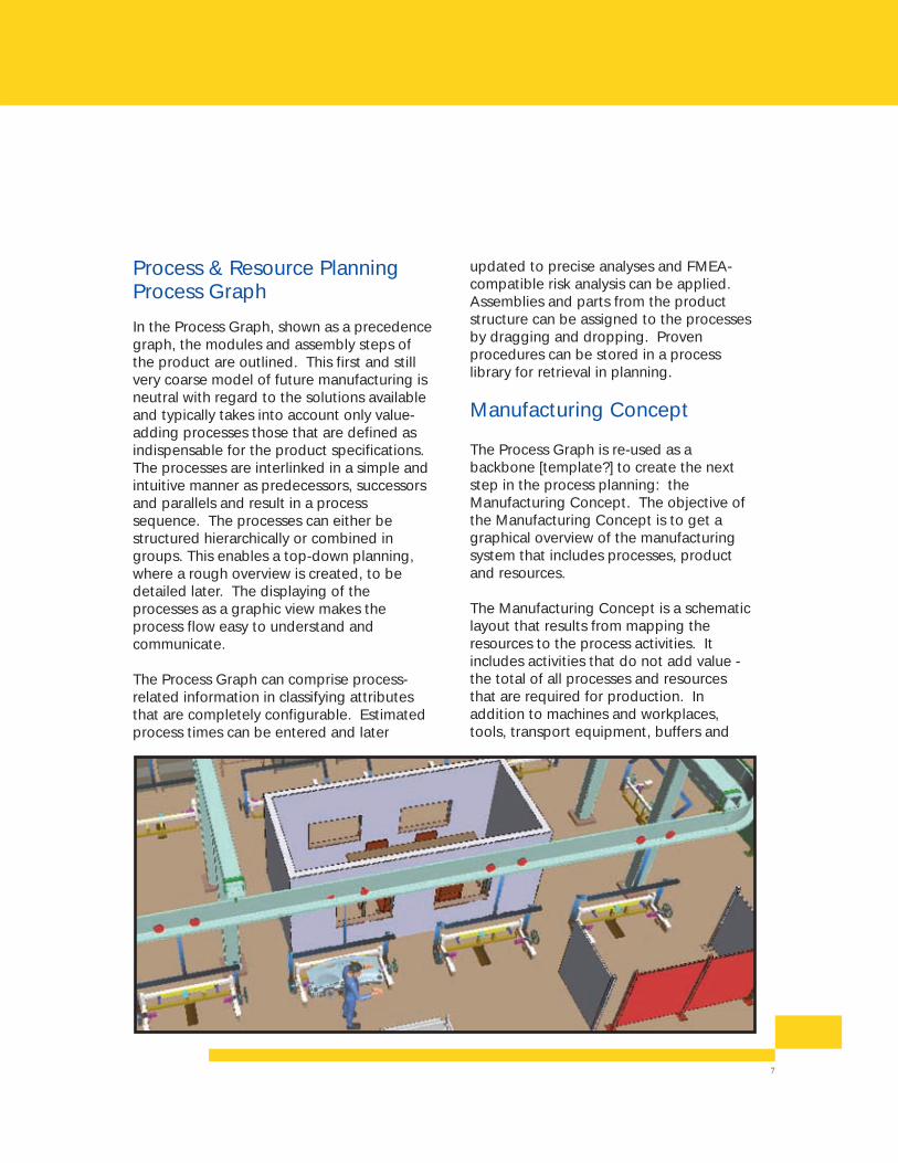
Manufacturing Concept
The Process Graph is re-used as abackbone [template?] to create the nextstep in the process planning: theManufacturing Concept. The objective ofthe Manufacturing Concept is to get agraphical overview of the manufacturingsystem that includes processes, productand resources.
The Manufacturing Concept is a schematiclayout that results from mapping theresources to the process activities. Itincludes activities that do not add value -the total of all processes and resourcesthat are required for production. Inaddition to machines and workplaces,tools, transport equipment, buffers and
8
test positions can be described in detail.The links between the objects are inheritedfrom the process graph and new links canbe added. The manufacturing conceptincludes human resource planning.
In the DELMIA PROCESS & RESOURCEPLANNING the planning premises such asshift models, wage groups and data forProduction Over Time are used in theManufacturing Concept to evaluate theresources. In this way, a rough estimate of
the cost and efficiency of the ManufacturingConcepts can be done. DELMIA PROCESS& RESOURCE PLANNING supports multipleManufacturing Concepts so the user can doseveral alternative concepts and use thebuilt-in functionality to compare theconcepts to find the most efficient and cost-saving alternatives.
By working with the capacity planning in
DELMIA PROCESS & RESOURCEPLANNING, the user gets a graphical view ofthe processes and resources, either as anoverview or as a detailed view, allowingefficient and accurate planning.
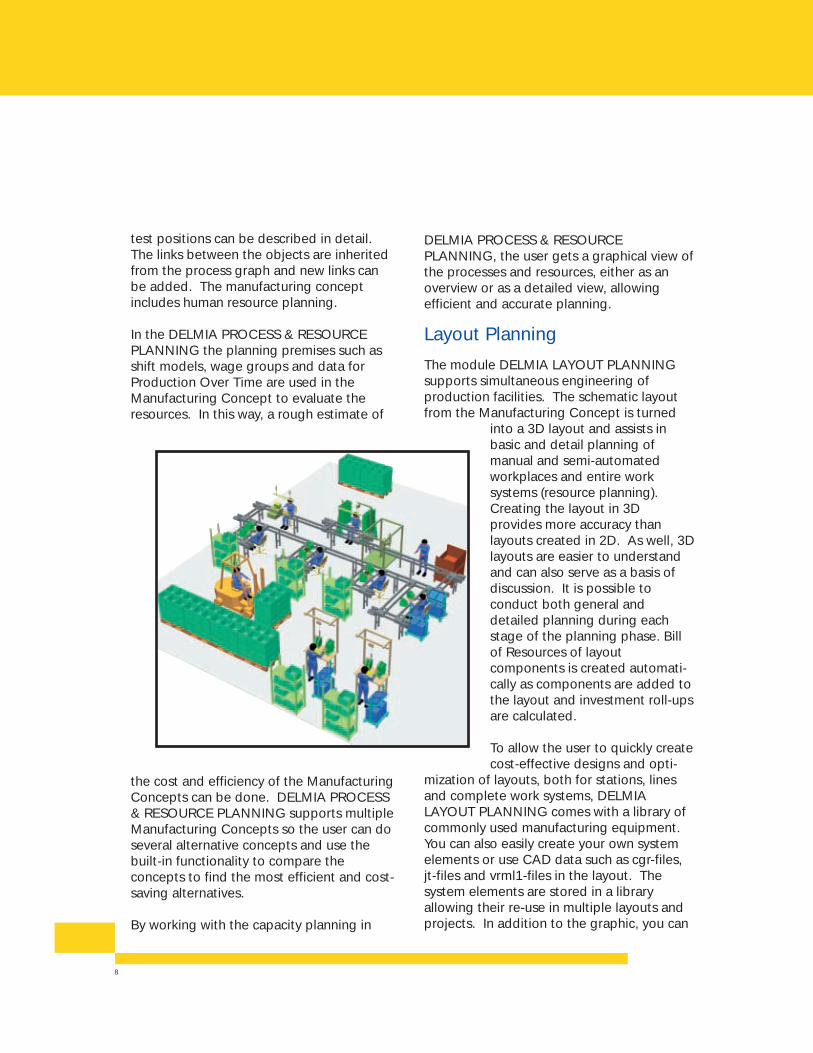
Layout Planning
The module DELMIA LAYOUT PLANNINGsupports simultaneous engineering ofproduction facilities. The schematic layoutfrom the Manufacturing Concept is turned
into a 3D layout and assists inbasic and detail planning ofmanual and semi-automatedworkplaces and entire worksystems (resource planning).Creating the layout in 3Dprovides more accuracy thanlayouts created in 2D. As well, 3Dlayouts are easier to understandand can also serve as a basis ofdiscussion. It is possible toconduct both general anddetailed planning during eachstage of the planning phase. Billof Resources of layoutcomponents is created automati-cally as components are added tothe layout and investment roll-upsare calculated.
To allow the user to quickly createcost-effective designs and opti-
mization of layouts, both for stations, linesand complete work systems, DELMIALAYOUT PLANNING comes with a library ofcommonly used manufacturing equipment.You can also easily create your own systemelements or use CAD data such as cgr-files,jt-files and vrml1-files in the layout. Thesystem elements are stored in a libraryallowing their re-use in multiple layouts andprojects. In addition to the graphic, you can
9
also store detailed written information aboutthe system elements in the database, such asname, manufacturer and purchase price.
The areas of use are
• Layout of Production Facilities• Design of the Material Flow• Layout of Workplaces• Selection, Dimensioning and Arrangement
of Operating Materials• Evaluation of the Workplace Layout
According to Ergonomic Criteria• Archiving and Documentation of the
Planning Results
The most important planning results are
• Bills of Resources with All Required Work System Elements
• 2D and 3D Workplace Views and Drawings
• Workplace Dimensions• Facility Layouts
The DELMIA LAYOUT PLANNING supportsthe quick, cost-effective design and optimiza-tion of ergonomically safe manual andpartially automated work systems.
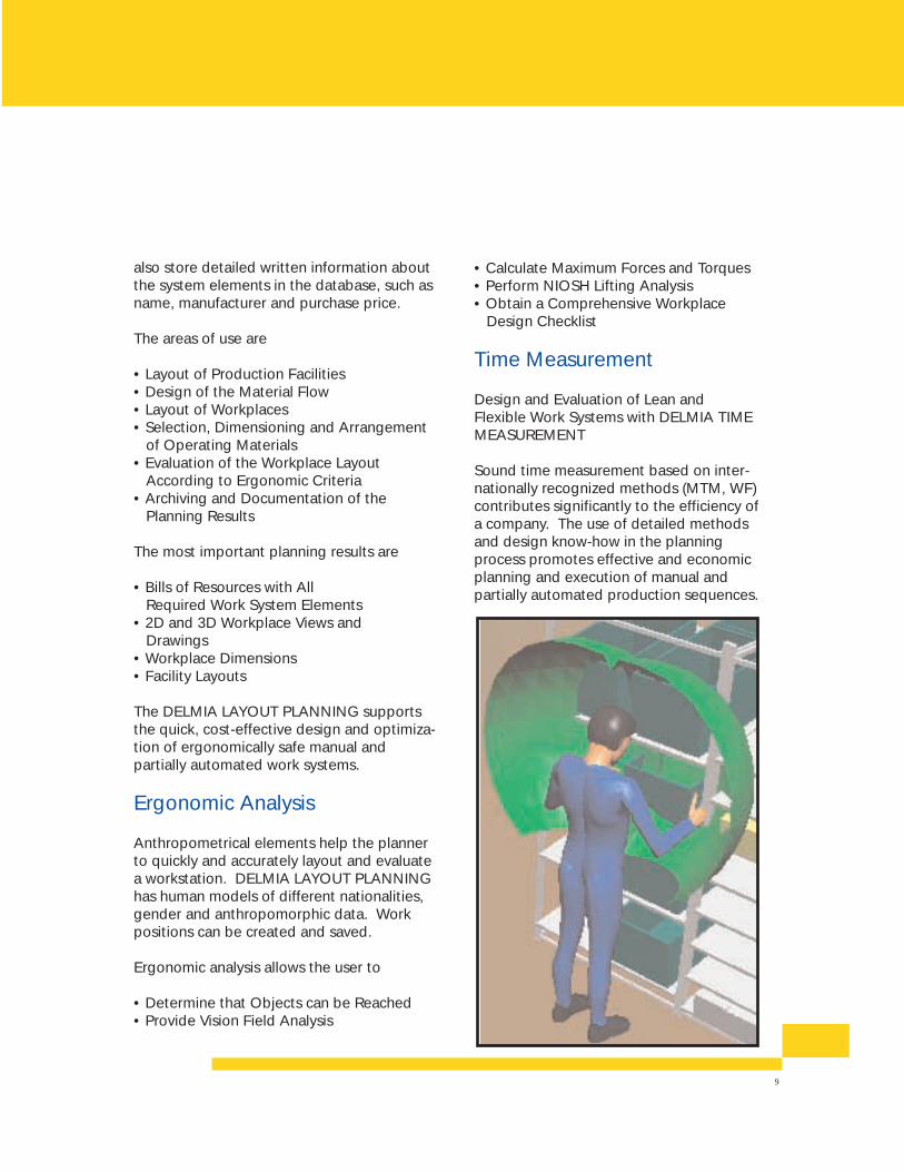
Ergonomic Analysis
Anthropometrical elements help the plannerto quickly and accurately layout and evaluatea workstation. DELMIA LAYOUT PLANNINGhas human models of different nationalities,gender and anthropomorphic data. Workpositions can be created and saved.
Ergonomic analysis allows the user to
• Determine that Objects can be Reached• Provide Vision Field Analysis
• Calculate Maximum Forces and Torques• Perform NIOSH Lifting Analysis• Obtain a Comprehensive Workplace
Design Checklist
Time Measurement
Design and Evaluation of Lean andFlexible Work Systems with DELMIA TIMEMEASUREMENT
Sound time measurement based on inter-nationally recognized methods (MTM, WF)contributes significantly to the efficiency ofa company. The use of detailed methodsand design know-how in the planningprocess promotes effective and economicplanning and execution of manual andpartially automated production sequences.
10
Major Advantages of DELMIATIME MEASUREMENT
• Quick and efficient generation of time analyses using all common analytical procedures (MTM and WF)
• Registration and management of estimated and recorded time values
• Creation of user-defined data cards• Creation of user-defined formulas for
determining process times• Design of user-defined print forms• Checking of rules for correctness and
completeness (MTM-1, UAS, MEK, MTM standard data, WF)
• High application speed through creation of time macros (library elements) and use of analysis templates
• Data compression capability over any number of data levels
• Structured data filing in work processes/workstations
• Flexible search mechanisms using key words and search patterns
• Time analysis directly associated with workstation layout
• Automatic updating of time values• Extensive user configuration options
Available Standard TimeMethods
• MTMo MTM-1o MTM-2o Standard datao UASo MEKo SAMo Office Taskso Visual Inspection
• Standard time method extensions are also supported in the individual analysis systems.
• Work Factoro Block Methodo Quick Method• General Time Element or Time Analysis
Modules of any quality obtained from anysource (estimated times, process times,planning time elements) are acquired andmanaged in this category.
Work Plans
The creation of work plans is supported inDELMIA TIME MEASUREMENT by a"summary" feature within a standard timemethod. Such summaries are used torepresent individual, integrally completeanalytical elements in an overall sequence orwork plan.In addition, this approach serves as a blockequalizer (time-determining time element)and can generate the work and textinstruction sheet - work instructions for theworker - directly at the workstation.Moreover, DELMIA TIME MEASUREMENTallows the user to create custom data cardsfor quick and easy integration of company-specific data.
Analysis with Data Cards
Graphical data cards facilitate quick andefficient creation of work sequence descrip-tions for manual and partially automatedworkstations. The desired activity is selectedby clicking in the data card with the mouse,then DELMIA TIME MEASUREMENTprompts for the associated time elementparameters, such as length of movement.From the data card element chosen, a
11
Nesting and control structures enable theuser to create highly dynamic formulas. Itis possible to calculate and plan a greatnumber of variants using only a fewformulas. This simplifies data maintenanceand increases the quality of the time data.
Benefits
• Quick and Efficient Generation of Time Analyses
• Creation of User-Defined Data Cards• Creation of User-Defined Formulas for
Determining Process Times• Design of User-Defined Print Forms• Checking of Rules for Accuracy and
Totality (MTM1, UAS, MEK, MTM Standard Data, WF)
complete line with code, standarddescription, quantity, frequency and time isgenerated. Naturally, user-defined timeelements can be inserted in the sequence ofoperations described wherever needed.
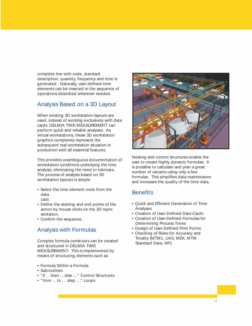
Analysis Based on a 3D Layout
When existing 3D workstation layouts areused, instead of working exclusively with datacards, DELMIA TIME MEASUREMENT canperform quick and reliable analyses. Asvirtual workstations, these 3D workstationgraphics completely represent thesubsequent real workstation situation inproduction with all essential features.
This provides unambiguous documentation ofworkstation conditions underlying the timeanalysis, eliminating the need to estimate.The process of analysis based on 3Dworkstation layouts is simple
• Select the time element code from the data card.
• Define the starting and end points of the action by mouse clicks on the 3D representation.
• Confirm the sequence.
Analysis with Formulas
Complex formula constructs can be createdand structured in DELMIA TIMEMEASUREMENT. This is implemented bymeans of structuring elements such as
• Formula Within a Formula• Subroutines• "if ... then ... else …" Control Structures • "from ... to … step …" Loops
w w w . d e l m i a . c o m
PR
OC
ES
S P
LAN
NIN
GDELMIA PROCESS ENGINEER
UUnniitteedd SSttaatteess DELMIA Corp.
Tel: + 1 248 267 9696 5500 New King Street
Fax:+ 1 248 267 8585 Troy, MI 48098
IIttaallyy DELMIA Division of
Dassault Systèmes S.r.l.
Tel: + 39 011 90407 70 Str. Torino, 43
Fax:+ 39 011 90407 62 10043 Orbassano
UUnniitteedd KKiinnggddoomm DELMIA Ltd.
Tel: + 44 15 65 75 11 21 Victoria Court, Bexton Road
Fax:+ 44 15 65 75 11 23 Knutsford, Cheshire
WA16 0PF
SSwweeddeenn DELMIA AB
Tel: + 46 31 720 58 00 Olof Asklundsgata 14
Fax:+ 46 31 89 96 25 Box 9180
40094 Gothenburg
JJaappaann DELMIA Japan Ltd.
Tel: + 81 45 470 8282 DAINI-UENO BLDG 9F,
Fax:+ 81 45 470 8283 3-7-18 Shin-Yokohama,
Kouhoku-ku, Yokohama-shi,
Kanagawa-ken 222-0033
FFrraannccee DELMIA France
Tel: + 33 1 55 57 55 61 133, Bureaux de la Colline
Fax:+ 33 1 55 57 55 60 92213 Saint Cloud Cedex
GGeerrmmaannyy DELMIA GmbH
Tel: + 49 711 27300 0 Raiffeisenplatz 4
Fax:+ 49 711 27300 599 70736 Fellbach
Tel: + 49 6135 9105 0 Am Kümmerling 24-26D
Fax:+ 49 6135 9105 99 55294 Bodenheim
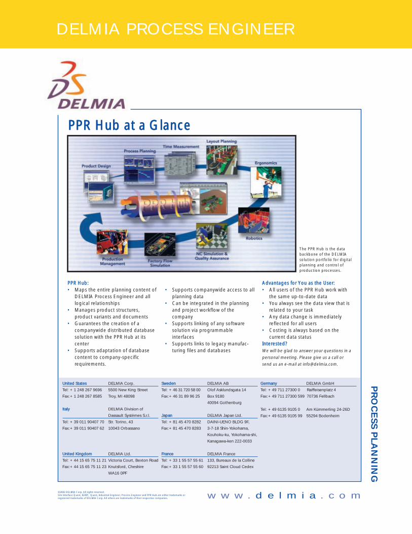
PPPPRR HHuubb aatt aa GGllaannccee
PPPPRR HHuubb:: • Maps the entire planning content of
DELMIA Process Engineer and alllogical relationships
• Manages product structures,product variants and documents
• Guarantees the creation of acompanywide distributed databasesolution with the PPR Hub at itscenter
• Supports adaptation of databasecontent to company-specificrequirements.
• Supports companywide access to allplanning data
• Can be integrated in the planningand project workflow of thecompany
• Supports linking of any softwaresolution via programmableinterfaces
• Supports links to legacy manufac-turing files and databases
AAddvvaannttaaggeess ffoorr YYoouu aass tthhee UUsseerr:: • All users of the PPR Hub work with
the same up-to-date data• You always see the data view that is
related to your task• Any data change is immediately
reflected for all users• Costing is always based on the
current data statusIInntteerreesstteedd??We will be glad to answer your questions in a
personal meeting. Please give us a call or
send us an e-mail at [email protected].
The PPR Hub is the databackbone of the DELMIAsolution portfolio for digitalplanning and control ofproduction processes.
©2002 DELMIA Corp. All rights reserved. Sim Interface Quest, IGRIP, Quest, Industrial Engineer, Process Engineer and PPR Hub are either trademarks orregistered trademarks of DELMIA Corp. All others are trademarks of their respective companies.