delta grounded wye transformers using - umn … for testing transformer differential relays applied...
TRANSCRIPT

Methods for Testing Transformer Differential Relays Applied to Delta‐Grounded Wye Transformers Using Single‐Phase Test Currents
Presented at: Minnesota Power Systems Conference
St. Paul, MN, USA November 11, 2015
Tom Ernst GE Digital Energy 4523 Jeremiah Rd. Cookeville, TN 38506 [email protected]
Craig Talbot Minnesota Power 30 West Superior St. Duluth, MN 55802 [email protected]
Abstract This paper provides an alternate method for testing transformer differential relays applied to delta‐grounded wye transformers using single‐phase test currents. The alternate method is based on the transformer three‐line diagram and transformer nameplate. This alternate method simulates actual current flows in the transformer during single‐line‐ground faults on the wye side and provides confirmation that the relay’s slope characteristics and phase shift settings are operating correctly. The alternate method is based on the transformer three‐line diagram and provides verification that the relay’s settings are correct for the transformer application. Three‐phase testing is not possible with some test sets due in part by the limited number of current channels available and, in some applications, test sets can also be limited by the high‐current values required for differential slope 2 region tests. Traditional methods of single‐phase testing typically
require the addition of √3 multipliers and other adjustments to account for zero‐sequence current removal, further increasing the magnitude of the test currents. Also, traditional tests (both 3‐phase and 1‐phase) use currents and phase shifts based on the relay settings. The alternate method improves both issues as only 2 channels are required of the test set and, since the test simulates real world, no multipliers are required. The alternate method uses two test currents that are always 180 degrees out of phase of each other for the differentially balanced condition regardless of the transformer phase shift lead or lag. As a result, the alternate method is especially useful for commission testing as it proves the transformer phase shift relay settings are correct for the transformer connection rather than testing the relay settings. Introduction
Testing of transformer differential characteristics can be challenging. Three‐phase testing, while straight forward from a magnitude and phase relationship point of view, requires 6 high‐amperage test currents. For delta ‐ grd wye winding transformers, traditional single‐phase testing requires non‐obvious multipliers and does not simulate real‐world fault conditions. This paper discusses an alternate method of single‐phase testing that simulates real‐world single‐phase loading conditions without the need for phase shifts or current multipliers. This alternate method verifies the differential relay settings are appropriate for the installed transformer by using the installation drawings and transformer nameplate diagram to determine the test connections. Application examples of installations at Minnesota Power substations are used to demonstrate the method.

Traditional 3‐Phase Testing Differential pick‐up tests can be performed using 3‐phase test currents. The magnitude of the currents required for pick‐up is typically low (10% ‐ 20% of full load) and only 3 current channels are required from the test set. For microprocessor relays, it is important to confirm that all three phases pick‐up when performing a 3‐phase test. Slope characteristic tests require simultaneous injection of test currents into a minimum of 2 relay windings. The magnitude relationship of the currents between the windings is based on the transformer three‐phase voltage ratio. The phase shift between the test currents is a function of the transformer internal and external connections. Determining the correct angle requires an examination of the substation 3‐line installation drawing and the transformer nameplate diagram. A thorough understanding of 3‐phase power is also required since the external connections can reverse the lead‐lag relationship of the windings if phases A, B and C are not connected to bushings 1, 2 and 3. Figure 1 shows an installation with a typical delta ‐ grd wye transformer with standard IEEE phase shift (secondary lags primary by 30°). In this installation the installed phase relationship matches the transformer nameplate phase relationship since phase A is on bushings 1, B is on bushings 2 and C is on bushings 3. The 3‐phase test current to simulate full load for this installation are also shown in figure 1.
Figure 1: Typical delta ‐ grd wye transformer and associated 3‐phase test currents
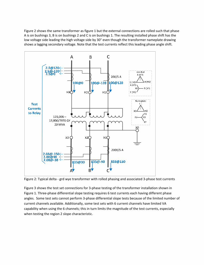
Figure 2 shows the same transformer as figure 1 but the external connections are rolled such that phase A is on bushings 3, B is on bushings 2 and C is on bushings 1. The resulting installed phase shift has the low voltage side leading the high voltage side by 30° even though the transformer nameplate drawing shows a lagging secondary voltage. Note that the test currents reflect this leading phase angle shift.
Figure 2: Typical delta ‐ grd wye transformer with rolled phasing and associated 3‐phase test currents Figure 3 shows the test set connections for 3‐phase testing of the transformer installation shown in
Figure 1. Three‐phase differential slope testing requires 6 test currents each having different phase
angles. Some test sets cannot perform 3‐phase differential slope tests because of the limited number of
current channels available. Additionally, some test sets with 6 current channels have limited VA
capability when using the 6 channels; this in turn limits the magnitude of the test currents, especially
when testing the region 2 slope characteristic.

Differen
tial Relay
Figure 3: 3‐Phase testing connections for the figure 1 transformer Traditional 1‐Phase Testing Traditional single‐phase testing of transformer differential relays, as shown in figure 4, inherently checks the functionality of each phase and requires only 2 injected currents. By only using 2 injected currents most relay test sets can perform this type of testing. However, injecting single‐phase currents for differential slope testing often requires multipliers and phase shifts that are not obvious from the substation and transformer 3‐line diagrams, especially for delta ‐ grd wye winding transformers.
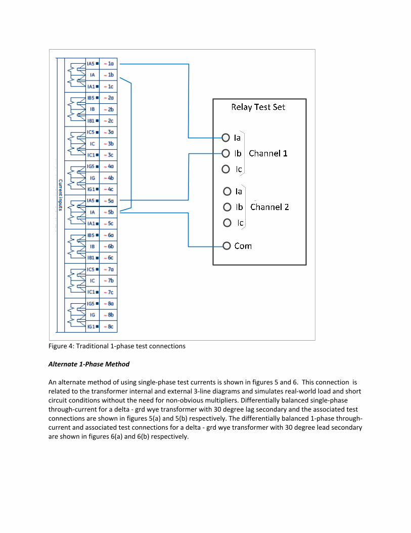
Figure 4: Traditional 1‐phase test connections
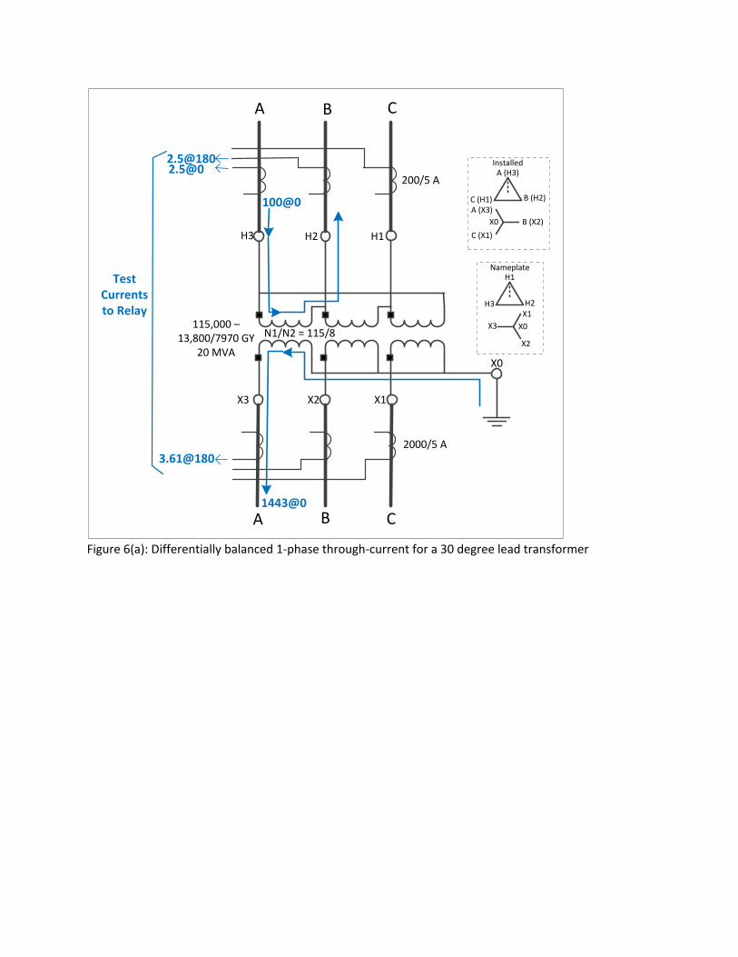
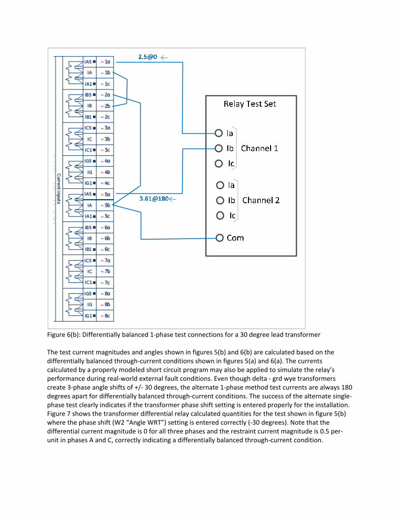
Alternate 1‐Phase Method An alternate method of using single‐phase test currents is shown in figures 5 and 6. This connection is related to the transformer internal and external 3‐line diagrams and simulates real‐world load and short circuit conditions without the need for non‐obvious multipliers. Differentially balanced single‐phase through‐current for a delta ‐ grd wye transformer with 30 degree lag secondary and the associated test connections are shown in figures 5(a) and 5(b) respectively. The differentially balanced 1‐phase through‐current and associated test connections for a delta ‐ grd wye transformer with 30 degree lead secondary are shown in figures 6(a) and 6(b) respectively.
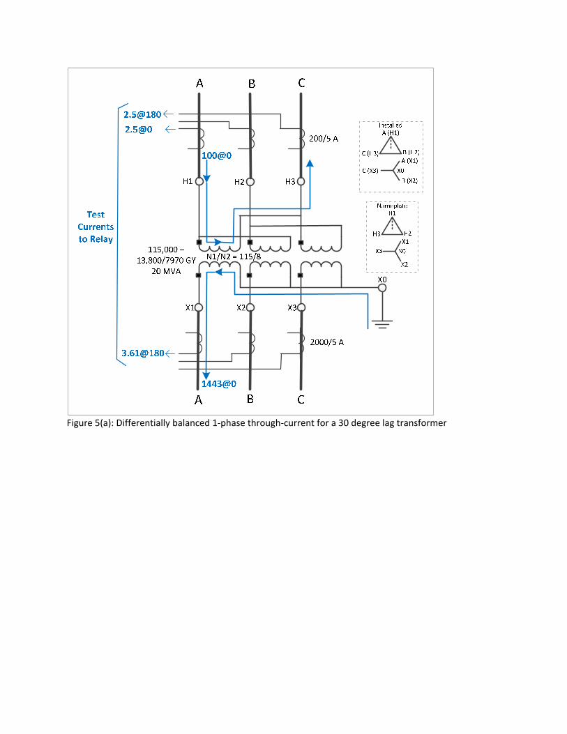
Figure 5(a): Differentially balanced 1‐phase through‐current for a 30 degree lag transformer
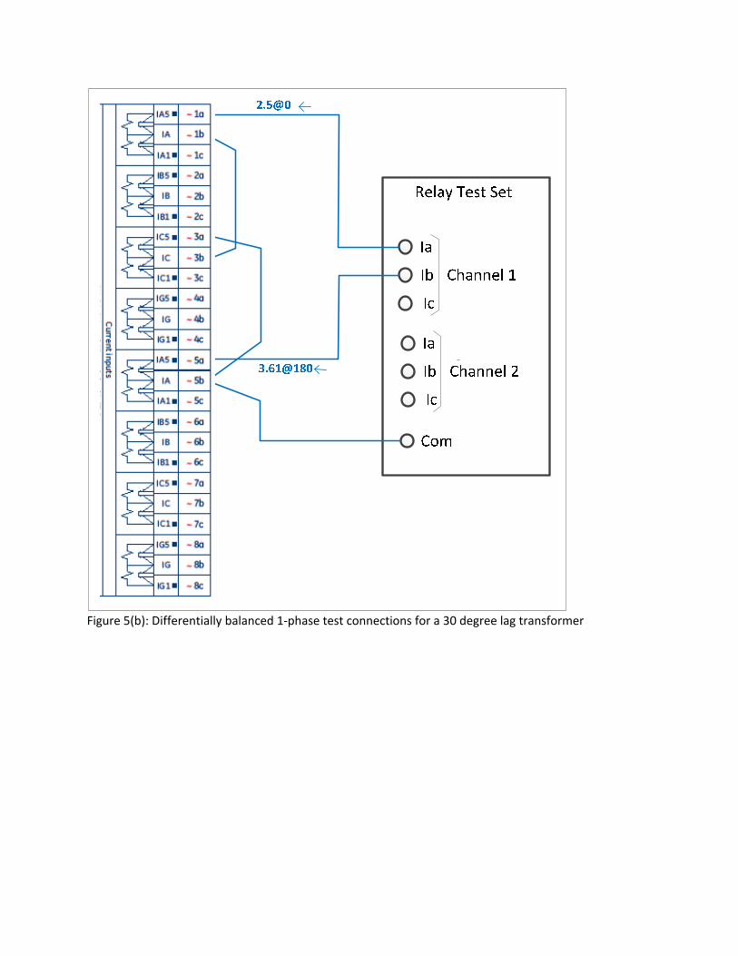
Figure 5(b): Differentially balanced 1‐phase test connections for a 30 degree lag transformer
X1X2X3
X0
H3 H2 H1
X0
X1
X2
X3
H1
H2H3
Nameplate
X0
A (H3)Installed
B (H2)C (H1)A (X3)
B (X2)
C (X1)
A B C
A B C
115,000 –13,800/7970 GY
20 MVA
2000/5 A
200/5 A
100@0
1443@0
3.61@180
Test Currents to Relay
N1/N2 = 115/8
Figure 6(a): Differentially balanced 1‐phase through‐current for a 30 degree lead transformer
Differen
tial Relay
Figure 6(b): Differentially balanced 1‐phase test connections for a 30 degree lead transformer The test current magnitudes and angles shown in figures 5(b) and 6(b) are calculated based on the differentially balanced through‐current conditions shown in figures 5(a) and 6(a). The currents calculated by a properly modeled short circuit program may also be applied to simulate the relay’s performance during real‐world external fault conditions. Even though delta ‐ grd wye transformers create 3‐phase angle shifts of +/‐ 30 degrees, the alternate 1‐phase method test currents are always 180 degrees apart for differentially balanced through‐current conditions. The success of the alternate single‐phase test clearly indicates if the transformer phase shift setting is entered properly for the installation. Figure 7 shows the transformer differential relay calculated quantities for the test shown in figure 5(b) where the phase shift (W2 “Angle WRT”) setting is entered correctly (‐30 degrees). Note that the differential current magnitude is 0 for all three phases and the restraint current magnitude is 0.5 per‐unit in phases A and C, correctly indicating a differentially balanced through‐current condition.
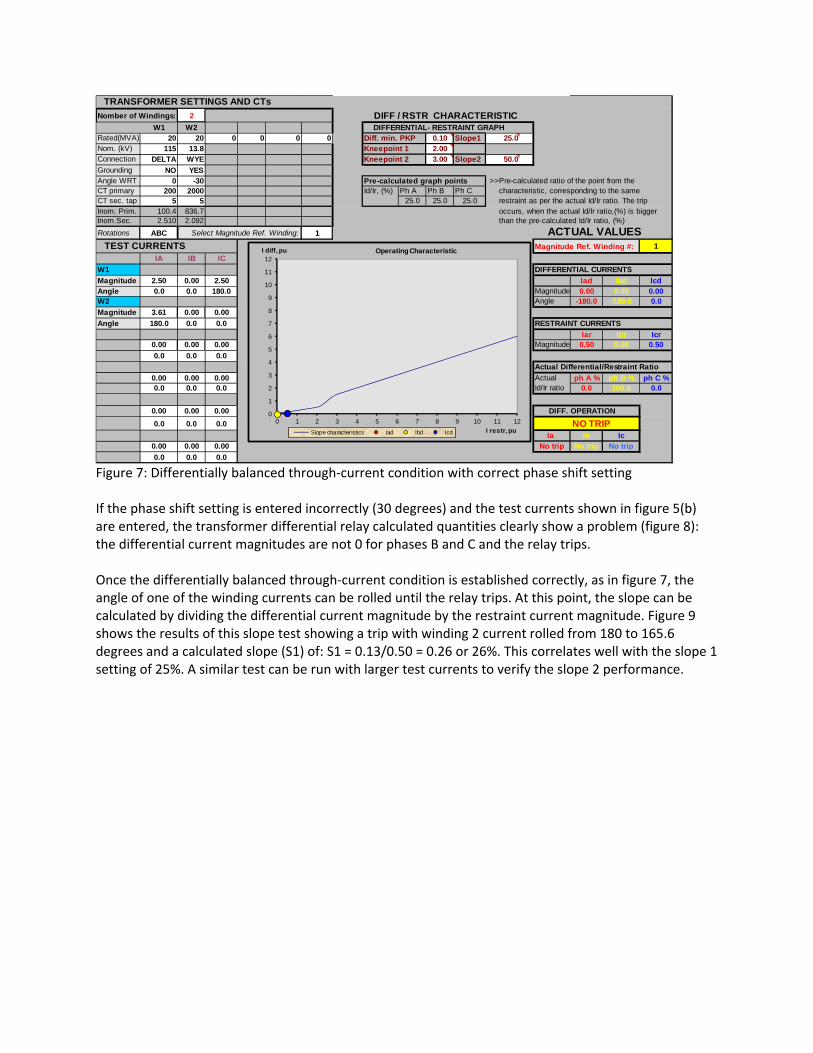
Figure 7: Differentially balanced through‐current condition with correct phase shift setting If the phase shift setting is entered incorrectly (30 degrees) and the test currents shown in figure 5(b) are entered, the transformer differential relay calculated quantities clearly show a problem (figure 8): the differential current magnitudes are not 0 for phases B and C and the relay trips. Once the differentially balanced through‐current condition is established correctly, as in figure 7, the angle of one of the winding currents can be rolled until the relay trips. At this point, the slope can be calculated by dividing the differential current magnitude by the restraint current magnitude. Figure 9 shows the results of this slope test showing a trip with winding 2 current rolled from 180 to 165.6 degrees and a calculated slope (S1) of: S1 = 0.13/0.50 = 0.26 or 26%. This correlates well with the slope 1 setting of 25%. A similar test can be run with larger test currents to verify the slope 2 performance.
TRANSFORMER SETTINGS AND CTs
Nomber of Windings: 2 DIFF / RSTR CHARACTERISTIC W1 W2 W3 W4 W5 W6 DIFFERENTIAL- RESTRAINT GRAPH
Rated(MVA) 20 20 0 0 0 0 Diff. min. PKP 0.10 Slope1 25.0Nom. (kV) 115 13.8 230 13.8 0.48 69 Kneepoint 1 2.00Connection DELTA WYE WYE WYE WYE WYE Kneepoint 2 3.00 Slope2 50.0
Grounding NO YES NO NO YES YESAngle WRT 0 -30 0 0 0 0 Pre-calculated graph points >>Pre-calculated ratio of the point from the CT primary 200 2000 2000 8000 3000 1000 Id/Ir, (%) Ph A Ph B Ph C characteristic, corresponding to the same CT sec. tap 5 5 5 5 5 5 25.0 25.0 25.0 restraint as per the actual Id/Ir ratio. The trip Inom. Prim. 100.4 836.7 0.0 0.0 0.0 0.0 occurs, when the actual Id/Ir ratio,(%) is biggerInom.Sec. 2.510 2.092 0.000 0.000 0.000 0.000 than the pre-calculated Id/Ir ratio, (%)
Rotations ABC 1 ACTUAL VALUES TEST CURRENTS Magnitude Ref. Winding #: 1
IA IB IC
W1 DIFFERENTIAL CURRENTS
Magnitude 2.50 0.00 2.50 Iad Ibd IcdAngle 0.0 0.0 180.0 Magnitude 0.00 0.00 0.00W2 Angle -180.0 -180.0 0.0
Magnitude 3.61 0.00 0.00
Angle 180.0 0.0 0.0 RESTRAINT CURRENTS
W3 Iar Ibr IcrMagnitude 0.00 0.00 0.00 Magnitude 0.50 0.00 0.50
Angle 0.0 0.0 0.0
W4 Actual Differential/Restraint Ratio
Magnitude 0.00 0.00 0.00 Actual ph A % ph B % ph C %Angle 0.0 0.0 0.0 Id/Ir ratio 0.0 100.0 0.0
W5
Magnitude 0.00 0.00 0.00 DIFF. OPERATION
Angle 0.0 0.0 0.0 NO TRIPW6 Ia Ib IcMagnitude 0.00 0.00 0.00 No trip No trip No trip
Angle 0.0 0.0 0.0
Select Magnitude Ref. Winding:
0
1
2
3
4
5
6
7
8
9
10
11
12
0 1 2 3 4 5 6 7 8 9 10 11 12
I diff, pu
I restr, pu
Operating Characteristic
Slope characteristics Iad Ibd Icd

Figure 8: Differentially balanced through‐current condition with incorrect phase shift setting
Figure 9: Slope verification test with winding 2 test current angle rolled to point of trip
TRANSFORMER SETTINGS AND CTs
Nomber of Windings: 2 DIFF / RSTR CHARACTERISTIC W1 W2 W3 W4 W5 W6 DIFFERENTIAL- RESTRAINT GRAPH
Rated(MVA) 20 20 0 0 0 0 Diff. min. PKP 0.10 Slope1 25.0Nom. (kV) 115 13.8 230 13.8 0.48 69 Kneepoint 1 2.00Connection DELTA WYE WYE WYE WYE WYE Kneepoint 2 3.00 Slope2 50.0
Grounding NO YES NO NO YES YESAngle WRT 0 30 0 0 0 0 Pre-calculated graph points >>Pre-calculated ratio of the point from the CT primary 200 2000 2000 8000 3000 1000 Id/Ir, (%) Ph A Ph B Ph C characteristic, corresponding to the same CT sec. tap 5 5 5 5 5 5 25.0 25.0 25.0 restraint as per the actual Id/Ir ratio. The trip Inom. Prim. 100.4 836.7 0.0 0.0 0.0 0.0 occurs, when the actual Id/Ir ratio,(%) is biggerInom.Sec. 2.510 2.092 0.000 0.000 0.000 0.000 than the pre-calculated Id/Ir ratio, (%)
Rotations ABC 1 ACTUAL VALUES TEST CURRENTS Magnitude Ref. Winding #: 1
IA IB IC
W1 DIFFERENTIAL CURRENTS
Magnitude 2.50 0.00 2.50 Iad Ibd IcdAngle 0.0 0.0 180.0 Magnitude 0.00 0.50 0.50W2 Angle -180.0 0.0 -180.0
Magnitude 3.61 0.00 0.00
Angle 180.0 0.0 0.0 RESTRAINT CURRENTS
W3 Iar Ibr IcrMagnitude 0.00 0.00 0.00 Magnitude 0.50 0.50 0.50
Angle 0.0 0.0 0.0
W4 Actual Differential/Restraint Ratio
Magnitude 0.00 0.00 0.00 Actual ph A % ph B % ph C %Angle 0.0 0.0 0.0 Id/Ir ratio 0.0 100.0 100.0
W5
Magnitude 0.00 0.00 0.00 DIFF. OPERATION
Angle 0.0 0.0 0.0 TRIPW6 Ia Ib IcMagnitude 0.00 0.00 0.00 No trip Trip Trip
Angle 0.0 0.0 0.0
Select Magnitude Ref. Winding:
0
1
2
3
4
5
6
7
8
9
10
11
12
0 1 2 3 4 5 6 7 8 9 10 11 12
I diff, pu
I restr, pu
Operating Characteristic
Slope characteristics Iad Ibd Icd
TRANSFORMER SETTINGS AND CTs
Nomber of Windings: 2 DIFF / RSTR CHARACTERISTIC W1 W2 W3 W4 W5 W6 DIFFERENTIAL- RESTRAINT GRAPH
Rated(MVA) 20 20 0 0 0 0 Diff. min. PKP 0.10 Slope1 25.0Nom. (kV) 115 13.8 230 13.8 0.48 69 Kneepoint 1 2.00Connection DELTA WYE WYE WYE WYE WYE Kneepoint 2 3.00 Slope2 50.0
Grounding NO YES NO NO YES YESAngle WRT 0 -30 0 0 0 0 Pre-calculated graph points >>Pre-calculated ratio of the point from the CT primary 200 2000 2000 8000 3000 1000 Id/Ir, (%) Ph A Ph B Ph C characteristic, corresponding to the same CT sec. tap 5 5 5 5 5 5 25.0 25.0 25.0 restraint as per the actual Id/Ir ratio. The trip Inom. Prim. 100.4 836.7 0.0 0.0 0.0 0.0 occurs, when the actual Id/Ir ratio,(%) is biggerInom.Sec. 2.510 2.092 0.000 0.000 0.000 0.000 than the pre-calculated Id/Ir ratio, (%)
Rotations ABC 1 ACTUAL VALUES TEST CURRENTS Magnitude Ref. Winding #: 1
IA IB IC
W1 DIFFERENTIAL CURRENTS
Magnitude 2.50 0.00 2.50 Iad Ibd IcdAngle 0.0 0.0 180.0 Magnitude 0.13 0.00 0.13W2 Angle -277.1 -194.4 -97.1
Magnitude 3.61 0.00 0.00
Angle 165.6 0.0 0.0 RESTRAINT CURRENTS
W3 Iar Ibr IcrMagnitude 0.00 0.00 0.00 Magnitude 0.50 0.00 0.50
Angle 0.0 0.0 0.0
W4 Actual Differential/Restraint Ratio
Magnitude 0.00 0.00 0.00 Actual ph A % ph B % ph C %Angle 0.0 0.0 0.0 Id/Ir ratio 25.1 100.0 25.1
W5
Magnitude 0.00 0.00 0.00 DIFF. OPERATION
Angle 0.0 0.0 0.0 TRIPW6 Ia Ib IcMagnitude 0.00 0.00 0.00 Trip No trip Trip
Angle 0.0 0.0 0.0
Select Magnitude Ref. Winding:
0
1
2
3
4
5
6
7
8
9
10
11
12
0 1 2 3 4 5 6 7 8 9 10 11 12
I diff, pu
I restr, pu
Operating Characteristic
Slope characteristics Iad Ibd Icd

Since the alternate method is a single‐phase test, it is necessary to repeat the test for each phase for a total of 3 connections for each winding pair. Tables 1 and 2 show test connections required for a 2 winding delta ‐ grd wye transformer with 30 degree lag (figures 5(a) & (b)) and lead (figures 6(a) & (b)) connections respectively. Table 1: Test connections for a 2 winding 30 degree lag delta‐wye connection transformer
Test ID Winding 1 (delta) connections Winding 2 (wye) connections
A In on A & out on C A
B In on B & out on A B
C In on C & out on B C
Table 2: Test connections for a 2 winding 30 degree lead delta‐wye connection transformer
Test ID Winding 1 (delta) connections Winding 2 (wye) connections
A In on A & out on B A
B In on B & out on C B
C In on C & out on A C
The traditional single‐phase test method requires injecting test currents with magnitudes and angles not obvious from the substation and transformer drawings while the alternate method current magnitudes and angles are visually related to the installed 3line diagram and the internal turns ratio (N1/N2) of the
transformer. However, a close inspection shows that a √3 multiplier is implied due to the relationship between the transformer 3‐phase voltage ratio and the internal turns ratio. As a result, the test currents for the alternate method are still larger than those required for 3‐phase testing. For this reason, it may still be difficult for some test sets to deliver high test currents to verify the region 2 slope. It should be possible to develop an automated test plan for the alternate single‐phase method which would select the test outputs from table 1 or table 2 depending on the phase shift setting. As such, the method could be used for maintenance testing. However, the method is uniquely suited for commission testing where the core activity of the method is to determine the test connections based on an examination of the installation drawings with the ultimate goal of verifying that the phase shift setting is correct for the installation. Application Examples Two application examples at Minnesota Power substations are included below. The first example is a distribution substation where the distribution voltage lags the transmission voltage. The second example is another distribution substation in a different division where the distribution voltage leads the transmission voltage. In both cases, IEEE standard phase shift transformers were installed (“X” side lags the “H” side by 30°). An analysis of a transformer differential relay operation caused by an incorrect phase shift setting is also included in the Application Examples section.
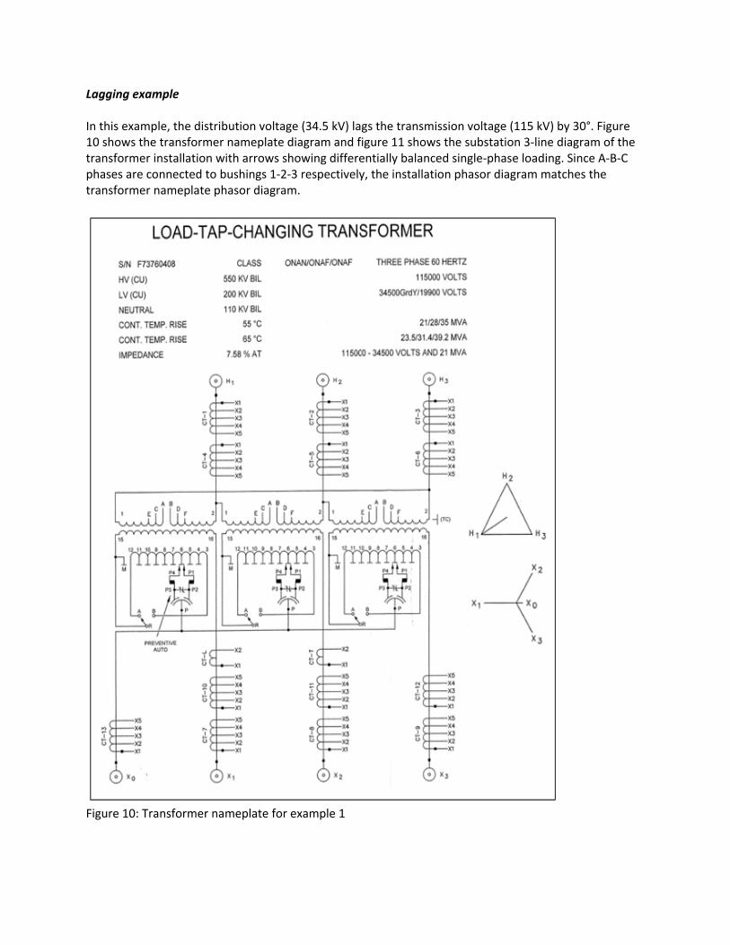
Lagging example In this example, the distribution voltage (34.5 kV) lags the transmission voltage (115 kV) by 30°. Figure 10 shows the transformer nameplate diagram and figure 11 shows the substation 3‐line diagram of the transformer installation with arrows showing differentially balanced single‐phase loading. Since A‐B‐C phases are connected to bushings 1‐2‐3 respectively, the installation phasor diagram matches the transformer nameplate phasor diagram.
Figure 10: Transformer nameplate for example 1

Minnesota Power uses a calculation sheet to document the basis of their relay settings and to define the commission tests to be performed. The commission testing definitions for the example 1 transformer differential slope characteristic are shown in figure 12. You will note that the test connections match with those shown in figure 5(b) and Table 1 for a 30° lag installation.
X0
A (H1)
B (H2)C (H3)A (X1)
B (X2)
C (X3)
1200/5 MR300/5 Tap
1200/5 MR1200/5 Tap
197 A
1137 A
3.28 @ 0°
4.73 @ 180°
N1/N2 = 115/19.9
Figure 11: 3‐line installation diagram for example 1 with differentially balanced 1‐phase load
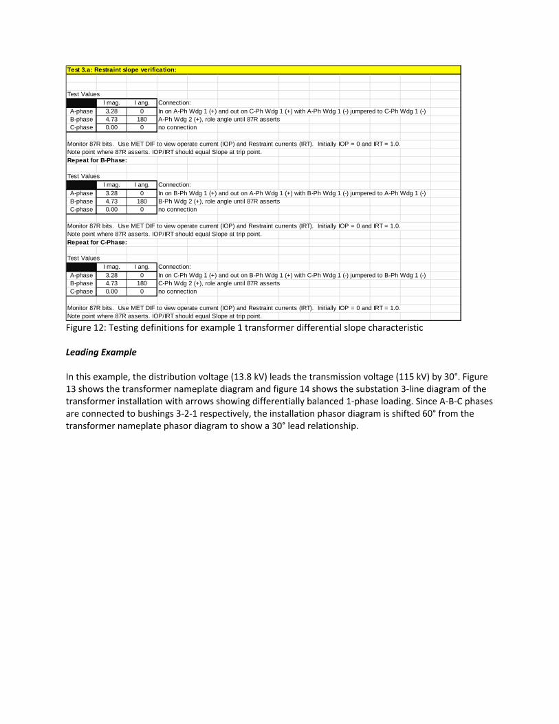
Figure 12: Testing definitions for example 1 transformer differential slope characteristic Leading Example In this example, the distribution voltage (13.8 kV) leads the transmission voltage (115 kV) by 30°. Figure 13 shows the transformer nameplate diagram and figure 14 shows the substation 3‐line diagram of the transformer installation with arrows showing differentially balanced 1‐phase loading. Since A‐B‐C phases are connected to bushings 3‐2‐1 respectively, the installation phasor diagram is shifted 60° from the transformer nameplate phasor diagram to show a 30° lead relationship.
Test 3.a: Restraint slope verification:
Test ValuesI mag. I ang. Connection:
A-phase 3.28 0 In on A-Ph Wdg 1 (+) and out on C-Ph Wdg 1 (+) with A-Ph Wdg 1 (-) jumpered to C-Ph Wdg 1 (-)B-phase 4.73 180 A-Ph Wdg 2 (+), role angle until 87R assertsC-phase 0.00 0 no connection
Note point where 87R asserts. IOP/IRT should equal Slope at trip point.Repeat for B-Phase:
Test ValuesI mag. I ang. Connection:
A-phase 3.28 0 In on B-Ph Wdg 1 (+) and out on A-Ph Wdg 1 (+) with B-Ph Wdg 1 (-) jumpered to A-Ph Wdg 1 (-)B-phase 4.73 180 B-Ph Wdg 2 (+), role angle until 87R assertsC-phase 0.00 0 no connection
Note point where 87R asserts. IOP/IRT should equal Slope at trip point.Repeat for C-Phase:
Test ValuesI mag. I ang. Connection:
A-phase 3.28 0 In on C-Ph Wdg 1 (+) and out on B-Ph Wdg 1 (+) with C-Ph Wdg 1 (-) jumpered to B-Ph Wdg 1 (-)B-phase 4.73 180 C-Ph Wdg 2 (+), role angle until 87R assertsC-phase 0.00 0 no connection
Note point where 87R asserts. IOP/IRT should equal Slope at trip point.Monitor 87R bits. Use MET DIF to view operate current (IOP) and Restraint currents (IRT). Initially IOP = 0 and IRT = 1.0.
Monitor 87R bits. Use MET DIF to view operate current (IOP) and Restraint currents (IRT). Initially IOP = 0 and IRT = 1.0.
Monitor 87R bits. Use MET DIF to view operate current (IOP) and Restraint currents (IRT). Initially IOP = 0 and IRT = 1.0.

Figure 13: Transformer nameplate for example 2 The commission testing definitions for the example 2 transformer differential slope characteristic are shown in figure 15. You will note that the test connections match with those shown in figure 6(b) and Table 2 for a 30° lead installation.
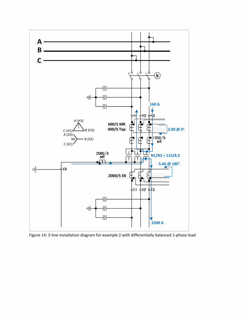
160 A
2.00 @ 0°
5.60 @ 180°
2240 A
X0
A (H3)
B (H2)C (H1)A (X3)
B (X2)
C (X1)
AB
C
600/5 MR400/5 Tap
2000/5 SR
N1/N2 = 115/8.2
Figure 14: 3‐line installation diagram for example 2 with differentially balanced 1‐phase load

Figure 15: Testing definitions for example 2 transformer differential slope characteristic Transformer Differential Relay Incorrect Operation Analysis Example Figure 16 shows a transformer through fault event that the relay incorrectly interrupted as an in‐zone differential fault and issued a trip. TRHA, TRHB, and TRHC are high side transformer currents. TRLA, TRLB, and TRLC are low side transformer currents and 1TA, 1TB, and 1TC are low side main breaker currents. This is a 2 winding delta – grd wye transformer. The low side (TRL_) currents are used for over‐current back‐up and the differential elements use the high side (TRH_) and low side main breaker (1T_) currents. Due to construction constraints, the transformer was not fully loaded before the B‐phase to ground feeder fault occurred. The load currents on the transformer were below the minimum pickup of the relay differential elements. During the trip investigation it was determined that the relay setting for phase angle compensation for the low voltage side of the transformer was compensated for a lagging relationship. In this installation, phases A‐B‐C are connected to bushing 3‐2‐1 resulting in the low side leading the high side by 30°. This type of connection can be seen in figure 4. The alternate method of testing was not used for commissioning of this transformer differential relay. For this application, if the test connections shown in figures 6(a) and 6(b) and table 2 were used, the phase angle compensation settings error may have been identified and a through fault trip of the differential relay may have been avoided.
Test 3.a: Restraint slope verification:
Test ValuesI mag. I ang. Connection:
A-phase 2.00 0 In on A-Ph Wdg 1 (+) and out on B-Ph Wdg 1 (+) with A-Ph Wdg 1 (-) jumpered to B-Ph Wdg 1 (-)B-phase 5.60 180 A-Ph Wdg 2 (+), role angle until 87R assertsC-phase 0.00 0 no connection
Use Differential and Restraint in Actual Values to view Differential current and Restraint current for A phase and B phase. C phase differentialand restraint currents should be 0 if the winding compensation factor (Angle WRT) is correct. Repeat for B-Phase:
Test ValuesI mag. I ang. Connection:
A-phase 2.00 0 In on B-Ph Wdg 1 (+) and out on C-Ph Wdg 1 (+) with B-Ph Wdg 1 (-) jumpered to C-Ph Wdg 1 (-)B-phase 5.60 180 B-Ph Wdg 2 (+), role angle until 87R assertsC-phase 0.00 0 no connection
Use Differential and Restraint in Actual Values to view Differential current and Restraint current for B phase and C phase. A phase differentialand restraint currents should be 0 if the winding compensation factor (Angle WRT) is correct. Repeat for C-Phase:
Test ValuesI mag. I ang. Connection:
A-phase 2.00 0 In on C-Ph Wdg 1 (+) and out on A-Ph Wdg 1 (+) with C-Ph Wdg 1 (-) jumpered to A-Ph Wdg 1 (-)B-phase 5.60 180 C-Ph Wdg 2 (+), role angle until 87R assertsC-phase 0.00 0 no connection
Use Differential and Restraint in Actual Values to view Differential current and Restraint current for C phase and A phase. B phase differentialand restraint currents should be 0 if the winding compensation factor (Angle WRT) is correct.
Monitor 87R bits and view the operate current (IOP) and restraint current (IRT).
Monitor 87R bits and view the operate current (IOP) and restraint current (IRT).
Monitor 87R bits and view the operate current (IOP) and restraint current (IRT).
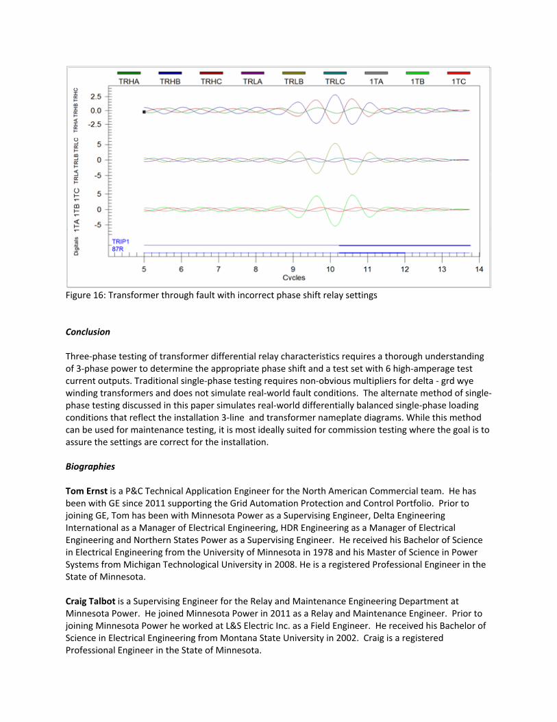
Figure 16: Transformer through fault with incorrect phase shift relay settings Conclusion Three‐phase testing of transformer differential relay characteristics requires a thorough understanding of 3‐phase power to determine the appropriate phase shift and a test set with 6 high‐amperage test current outputs. Traditional single‐phase testing requires non‐obvious multipliers for delta ‐ grd wye winding transformers and does not simulate real‐world fault conditions. The alternate method of single‐phase testing discussed in this paper simulates real‐world differentially balanced single‐phase loading conditions that reflect the installation 3‐line and transformer nameplate diagrams. While this method can be used for maintenance testing, it is most ideally suited for commission testing where the goal is to assure the settings are correct for the installation. Biographies Tom Ernst is a P&C Technical Application Engineer for the North American Commercial team. He has been with GE since 2011 supporting the Grid Automation Protection and Control Portfolio. Prior to joining GE, Tom has been with Minnesota Power as a Supervising Engineer, Delta Engineering International as a Manager of Electrical Engineering, HDR Engineering as a Manager of Electrical Engineering and Northern States Power as a Supervising Engineer. He received his Bachelor of Science in Electrical Engineering from the University of Minnesota in 1978 and his Master of Science in Power Systems from Michigan Technological University in 2008. He is a registered Professional Engineer in the State of Minnesota. Craig Talbot is a Supervising Engineer for the Relay and Maintenance Engineering Department at Minnesota Power. He joined Minnesota Power in 2011 as a Relay and Maintenance Engineer. Prior to joining Minnesota Power he worked at L&S Electric Inc. as a Field Engineer. He received his Bachelor of Science in Electrical Engineering from Montana State University in 2002. Craig is a registered Professional Engineer in the State of Minnesota.