delta xrd - rmspl.com.au · 3 technical data xrd w w w . r m s p l . c o m . a u rms supervision...
TRANSCRIPT

Delta XRD
w w w . r m s p l . c o m . a u
rms
X RD | G 6 | 1 9 / 0 5 / 2 0 1 7
Supervision Relays The XRD is a compact high performance supervision relay for power utility protection and control applications.
> Trip supply supervision
> Trip circuit supervision
> Supervision HEALTHY green LED
> Hand reset alarm flag
> Optional self-reset red alarm LED
> Surface or rail mount
> Flush panel or rack mount
> Made in Australia
A U X I L I A R Y | T R I P P I N G | S U P E R V I S I O N
AUXILIARY | TRIPPING | SUPERVISION

Functional Description
XRD
2
w w w . r m s p l . c o m . a u
rms
Application
The Delta XR Series Relays are low burden electro-mechanical
supervision relays for application on high security tripping and
auxiliary supply circuits.
The Delta XR relays have been designed to provide a balance of
low burden to minimize the possibility of circuit breaker mal-
operation while maintaining a minimum contact whetting
current to avoid nuisance alarm conditions.
A key feature of the design is a high visibility mechanical flag
indicator that can only be reset under healthy supervision
conditions. Versions with a self-reset alarm LED may be selected
as a lower cost option. A green Healthy LED is standard. Failure
of the circuit or supply being supervised will cause the main
relay element to drop out, an alarm signalled via the flag or red
LED and the alarm contacts to change state.
A wide voltage range and standard hand reset flag reduces the
number of model variations. The Delta range is packaged in a
size 2, 2U high case that may be flush panel, rack or rail
mounted.
A plug in terminal block is provided to allow panel pre-wiring.
Model Designation
DELTA XRD MODELS:
> XRD-4 Trip supply supervision with hand-reset
mechanical flag alarm indication
> XRD-5 Trip supply supervision with self-reset LED alarm
indication
> XRD-6 Trip circuit supervision with hand reset
mechanical flag alarm indication
> XRD-7 Trip circuit supervision with self-reset LED alarm
indication
Features
> High visibility electro-mechanical flag indication drops to indicate supervision alarm condition
> Optional low cost red LED alarm indication > Supervision Healthy LED > Two, three or four C/O alarm contacts > Rated operate voltages available for 24,
30/32, 48, 110, 125, 220, 240 or 250 Volts DC nominal auxiliary supplies
> Panel, rack or rail mount options > Compact size 2, 2U high case > Plug-in terminal block > M4 screw terminals
3
Technical Data
XRD
w w w . r m s p l . c o m . a u
rms
Supervision Healthy LED
A front panel green LED is provided to indicate when the
supervised circuit is HEALTHY.
Alarm Contacts
All contacts operate (Pick-up), when the monitored circuit is in
the HEALTHY condition. FAILURE of the supervision circuit will
cause the alarm contacts to drop out.
Hand Reset Flag
A high visibility mechanical flag drops when the supervised
circuit status changes from the HEALTHY to the FAIL condition.
The flag can only be manually hand reset using the front panel
reset slide after the supervision fail condition has been
corrected.
Self Reset Red LED Flag
A red LED flag is illuminated when the supervised circuit status
changes from the HEALTHY to the FAIL condition. The flag will
automatically extinguish after the supervision fail condition has
been corrected. The front panel slide switch is not fitted to XRD
versions with the LED flag option.
Nominal Operating Voltages
24, 32, 48, 110, 125, 220, 240 and 250V DC available.
Terminal Block
TBD-R1 /R2 Rear connect terminal block
Suitable for flush mount relay version
TBD-F Front connect terminal block
Suitable for rail mount relay version
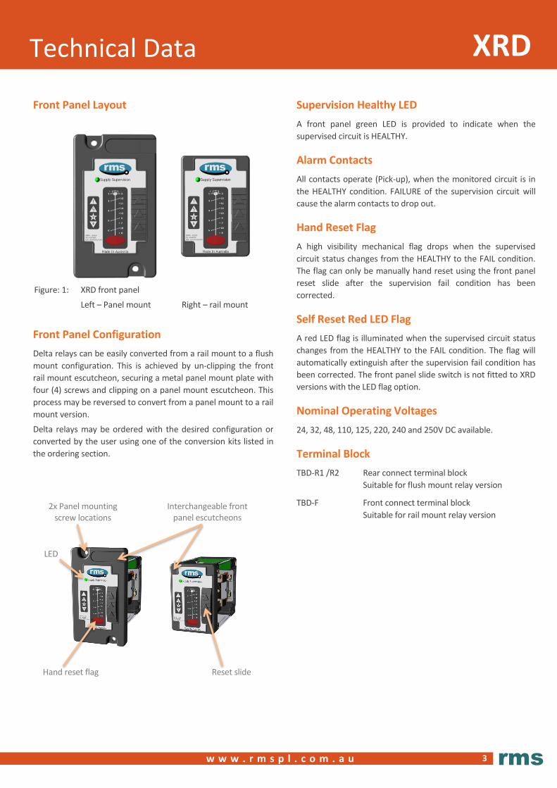
Front Panel Layout
Front Panel Configuration
Delta relays can be easily converted from a rail mount to a flush
mount configuration. This is achieved by un-clipping the front
rail mount escutcheon, securing a metal panel mount plate with
four (4) screws and clipping on a panel mount escutcheon. This
process may be reversed to convert from a panel mount to a rail
mount version.
Delta relays may be ordered with the desired configuration or
converted by the user using one of the conversion kits listed in
the ordering section.
Figure: 1: XRD front panel
Left – Panel mount Right – rail mount
Hand reset flag
Reset slide
LED
2x Panel mounting screw locations
Interchangeable front panel escutcheons

4
DC Supply Supervision XRD-4
w w w . r m s p l . c o m . a u
rms
Description
The XRD-4 is designed to supervise the DC auxiliary supply
employed on high security protection and tripping circuits
employed in high voltage power systems. The XRD-4 comprises
a heavy-duty attracted armature control relay with a single
operating coil and delay slug.
Under healthy conditions, the coil is energized and if the supply
fails, the relay will drop out to initiate a supply fail alarm. A time
delay is incorporated to avoid nuisance tripping due to
switching transients.
Supervision Circuit Burden
The XRD-4 circuit design is optimized to minimize the
supervision current to minimize the burden on the supervised
DC supply. The maximum XRD-4 burdens are as follows:
Nominal Healthy
24V 4.0W
32V 5.0W
48V 4.5W
110V 4.5W
125V 4.5W
220V 5.5W
240V 6.0W
250V 6.0W
Thermal Rating
All circuits are designed to withstand continuous application of
120% of nominal voltage.
Operating Voltage Range
70% to 120% of nominal continuous at 25 degrees Celsius
Drop-out Voltage
The highest voltage level at which the relay will drop out and
signal an alarm is 70% of nominal.
The lowest voltage level at which the relay will remain picked up
is 60% of nominal. Below 60% of nominal an alarm signal
condition is guaranteed.
Drop-out Time 300 to 600ms at 25 degrees Celsius
Reset When the supervision fault is rectified the contacts will self-
reset to the picked up healthy state. The mechanical flag
indicator must be hand reset.
Normal Operating Conditions
AUXILIARY SUPPLY AVAILABLE
Figure 5 shows a typical DC auxiliary supply circuit with the XRD-
4 employed to supervise the auxiliary supply. The blue lines
depict the supervised circuits and red arrows depict the path of
the supervision current with a healthy auxiliary supply applied.
Figure 5: Delta XRD-4 - Normal system condition
Abnormal Operating Condition
AUXILIARY SUPPLY FAIL – ALARM CONDITION
Figure 6 shows the XRD-4 supervision relay dropped out due to
the loss of auxiliary supply. Loss of the supervision current due
to a loss of the auxiliary supply for <300ms will not cause this
condition. Loss of supply will cause the green HEALTHY LED to
be extinguished.
An alarm is reported through the change in state of the four (4)
alarm contacts and the front panel hand reset flag indicator.
Figure 6: Delta XRD-4 - Abnormal condition – Loss of supply
+ -
9
7
8
1 0
1 4
1 3
1 2
11
4
3
5
6
1 2X R D
V m o ni to r
+ -
9
7
8
1 0
1 4
1 3
1 2
11
4
3
5
6
>200
ms
dela
y
A L A R M C O N D IT IO N
1 2X R D
V m o ni to r
5
DC Supply Supervision
XRD-5
w w w . r m s p l . c o m . a u
rms
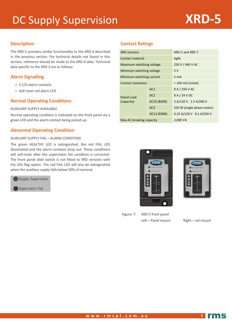
Figure: 7: XRD-5 front panel
Left – Panel mount Right – rail mount
Description
The XRD-5 provides similar functionality to the XRD-4 described
in the previous section. For technical details not found in this
section, reference should be made to the XRD-4 data. Technical
data specific to the XRD-5 are as follows:
Alarm Signalling
> 2 C/O alarm contacts
> Self-reset red alarm LED
Normal Operating Conditions
AUXILIARY SUPPLY AVAILABLE
Normal operating condition is indicated on the front panel via a
green LED and the alarm contact being picked up.
Abnormal Operating Condition
AUXILIARY SUPPLY FAIL – ALARM CONDITION
The green HEALTHY LED is extinguished, the red FAIL LED
illuminated and the alarm contacts drop out. These conditions
will self-reset after the supervision fail condition is corrected.
The front panel slide switch is not fitted to XRD versions with
the LED flag option. The red FAIL LED will also be extinguished
when the auxiliary supply falls below 50% of nominal.
Contact Ratings
XRD versions XRD-5 and XRD-7
Contact material AgNi
Maximum switching voltage 250 V / 440 V AC
Minimum switching voltage 5 V
Minimum switching current 5 mA
Contact resistance < 100 mΩ (initial)
Rated Load (capacity)
AC1 8 A / 250 V AC
DC1 8 A / 24 V DC
AC15 (B300) 3 A/120 V 1.5 A/240 V
AC3 550 W (single phase motor)
DC13 (R300) 0.22 A/120 V 0.1 A/250 V
Max AC breaking capacity 2,000 VA

6
w w w . r m s p l . c o m . a u
rms
Trip Circuit Supervision XRD-6
Description
The operating element of the XRD-6 comprises two supervision
elements A and B, which combine to hold in a heavy duty 3
contact attracted armature relay.
Supervision is active with the circuit breaker in the open or
closed position via the “a and b” CB auxiliary contacts.
Supervision also remains active during tripping operations and
irrespective of the status of the tripping relay contact
An important characteristic of the design is the low level of
current required to flow through the CB coil for correct
operation of the supervision scheme. A constant low
supervision current is maintained irrespective of the circuit
breaker open or closed position. This results in low power
dissipation in the XRD-6 circuit and the circuit breaker coil which
reduces the possibility of nuisance tripping.
Supervision with Circuit De-energized
CIRCUIT BREAKER OPEN AND TRIP CONTACT OPEN
Figure 8 shows a typical tripping circuit with the XRD-6
employed to supervise the circuit continuity, the circuit breaker
coil and the auxiliary supply.
The blue lines depict the supervised circuits and red arrows the
path of the supervision current through supervision element A
with the auxiliary supply applied and the circuit breaker open.
Figure 8: Delta XRD-6 – CB open
Functional Diagrams
Figures 8 to 13 depict how the supervision elements A and B
monitor circuit continuity under all conditions:
Figure 8 CB open Trip contact open
Auxiliary
supply
available
Figure 9 CB closing Trip contact open
Figure 10 CB closed Trip contact open
Figure 11 CB opening Trip contact closed
Figure 12 CB open Trip contact closed
Figure 13 Alarm condition
Supervision during Circuit Breaker Closure
CIRCUIT BREAKER CLOSING AND TRIP CONTACT OPEN
Closure of the circuit breaker could cause the supervision
circuits to be interrupted for the duration of the circuit breaker
operate time. During this interval a >400 ms time delay holds in
the alarm relay contacts.
Figure 9 shows the loss of supervision current through both the
A and B supervision elements for the duration of the circuit
breaker operating period.
Figure 9: Delta XRD-6 - CB closing
+CB A u x S w itc h
5 2 - b
T r ip C oil
52
T
5 2 - a
P ro te c t io n
T r ip C o nta c t
T r
-
V m -a
X R D
V m
-b
2
9
7
8
1 0
1 4
1 2
1 3
11
3
4
1
5
6
+C B A ux S w itc h
5 2 - b
T r ip C oil
52
T
5 2 - a
P ro te c t io n
T r ip C o nta c t
T r
-
V m -a
X R D
V m
-b
9
7
8
1 0
1 4
1 2
1 3
11
3
4
1
5
6
> 4 0 0 m s d e la y
T R A N S IE N T
IN D E T E R M IN AT E
C O N D IT IO N
7
w w w . r m s p l . c o m . a u
rms
Trip Circuit Supervision XRD-6
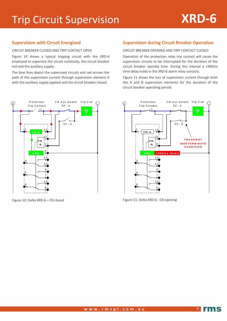
Supervision with Circuit Energized
CIRCUIT BREAKER CLOSED AND TRIP CONTACT OPEN
Figure 10 shows a typical tripping circuit with the XRD-6
employed to supervise the circuit continuity, the circuit breaker
coil and the auxiliary supply.
The blue lines depict the supervised circuits and red arrows the
path of the supervision current through supervision element A
with the auxiliary supply applied and the circuit breaker closed.
Figure 10: Delta XRD-6 – CB closed
Supervision during Circuit Breaker Operation
CIRCUIT BREAKER OPENING AND TRIP CONTACT CLOSED
Operation of the protection relay trip contact will cause the
supervision circuits to be interrupted for the duration of the
circuit breaker operate time. During this interval a >400ms
time delay holds in the XRD-6 alarm relay contacts.
Figure 11 shows the loss of supervision current through both
the A and B supervision elements for the duration of the
circuit breaker operating period.
Figure 11: Delta XRD-6 - CB opening
+C B A ux S w itc h
5 2 - b
T r ip C oil
52
T
5 2 - a
P ro te c t io n
T r ip C o nta c t
T r
-
V m -a
X R D
V m
-b
2
9
7
8
1 0
1 4
1 2
1 3
11
3
4
1
5
6
+C B A u x S w itc h
5 2 - b
T r ip C oil
52
T
5 2 - a
P ro te c t io n
T r ip C o nta c t
T r
-
V m -a
X R D
V m
-b
9
7
8
1 0
1 4
1 2
1 3
11
3
4
1
5
6
> 4 0 0 m s d e la y
T R A N S IE N T
IN D E T E R M IN AT E
C O N D IT IO N
8
w w w . r m s p l . c o m . a u
rms
Trip Circuit Supervision XRD-6
+ CB Aux Switch
52 - b
Trip Coil
52T
52 - a Protection
Trip ContactTr
-
ALARMCONDITION
Vm-a
XRD
Vm-b
2
9
7
8
10
14
12
13
11
3
4
1
5
6
CONTACTS
DROPPED OUTTO INDI CATE
CIRCUIT FAILURE
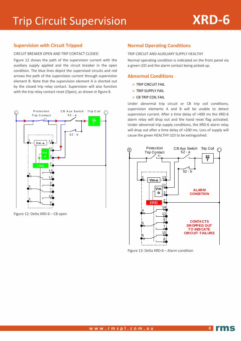
Normal Operating Conditions
TRIP CIRCUIT AND AUXILIARY SUPPLY HEALTHY
Normal operating condition is indicated on the front panel via
a green LED and the alarm contact being picked up.
Abnormal Conditions
> TRIP CIRCUIT FAIL
> TRIP SUPPLY FAIL
> CB TRIP COIL FAIL
Under abnormal trip circuit or CB trip coil conditions,
supervision elements A and B will be unable to detect
supervision current. After a time delay of >400 ms the XRD-6
alarm relay will drop out and the hand reset flag activated.
Under abnormal trip supply conditions, the XRD-6 alarm relay
will drop out after a time delay of >200 ms. Loss of supply will
cause the green HEALTHY LED to be extinguished.
Figure 13: Delta XRD-6 – Alarm condition
Supervision with Circuit Tripped
CIRCUIT BREAKER OPEN AND TRIP CONTACT CLOSED
Figure 12 shows the path of the supervision current with the
auxiliary supply applied and the circuit breaker in the open
condition. The blue lines depict the supervised circuits and red
arrows the path of the supervision current through supervision
element B. Note that the supervision element A is shorted out
by the closed trip relay contact. Supervision will also function
with the trip relay contact reset (Open), as shown in figure 8.
Figure 12: Delta XRD-6 – CB open
+C B A ux S w itc h
5 2 - b
T r ip C oil
52
T
5 2 - a
P ro te c t io n
T r ip C o nta c t
T r
-
V m -a
X R D
V m
-b
2
9
7
8
1 0
1 4
1 2
1 3
11
3
4
1
5
6

9
w w w . r m s p l . c o m . a u
rms
Trip Circuit Supervision XRD-6
Trip Circuit Resistance & Supervision Current
The XRD-6 circuit design is optimized to minimize the
supervision current in the CB trip coil to avoid the possibility of
nuisance tripping. Combined resistance of the circuit breaker
and CB trip coil must be less than the maximum tabulated
below to ensure adequate supervision current flows through
the XRD-6.
CB Open (52a Open and 52b Closed)
Nominal
Maximum CB trip coil
resistance (ohms)
Approximate voltage monitor
equivalent resistance
(ohms)
Supervision current *
(mA)
24V 1K 22K5 0.6-1.4
32V 2K5 30K 0.6-1.4
48V 5K 32K 0.7-1.4
110V 20K 96K 0.7-1.4
125V 23K 110K 0.7-1.4
220V 49K 190K 0.7-1.4
240V 34K 220K 0.7-1.4
250V 45K 220K 0.7-1.4
CB Closed (52a Closed and 52b Open)
Nominal
Maximum CB trip coil
resistance (ohms)
Approximate voltage monitor
equivalent resistance
(ohms)
Supervision current *
(mA)
24V 1K 45K 0.25-0.8
32V 2K5 60K 0.25-0.8
48V 5K 64K 0.3-0.8
110V 20K 192K 0.3-0.8
125V 23K 220K 0.3-0.8
220V 40K 360K 0.3-0.8
240V 43K 440K 0.3-0.8
250V 45K 440K 0.3-0.8
Operating Voltage Range
70% to 120% of nominal continuous at 25 degrees Celsius
Drop-out Voltage
The highest voltage level at which the relay will drop out and
signal an alarm is 70% of nominal.
The lowest voltage level at which the relay will remain picked up
is 35% of nominal. An alarm signal condition is output for input
voltages below 35% of nominal.
Drop-out Time
Trip circuit fail: 400-550 ms
Loss of supply: 200-400 ms
Trip Supply Burden
The actual operating burden is dependent on the combined
circuit breaker and CB trip circuit wiring.
Alarm Circuit Burden
The maximum XRD-6 relay burdens are as follows.
Nominal Healthy Alarmed Supervision
24V 4.5W 0.3W 0.05W
32V 5.0W 0.5W 0.05W
48V 4.5W 0.75W 0.08W
110V 4.5W 1.0W 0.20W
125V 4.5W 1.0W 0.25W
220V 5.5W 1.9W 0.40W
240V 5.5W 2.0W 0.40W
250V 5.5W 2.0W 0.45W
Alarm Contacts
Standard: 3 C/O
Tripping Relays
Self-reset or latching type lockout type tripping relays may be
employed with the XRD-6 trip circuit supervision scheme.
Contact Ratings
XRD versions XRD-4 and XRD-6
Contact material Ag
Operating Voltage Voltage free
Isolation across open contacts
1 kV rms
Make and carry 10 A continuous
Peak inrush current 200 A
AC break capacity AC1 10A / 230 V
DC break capacity DC1 1A / 110 V
Switching voltage: Maximum Minimum
300 V dc / 440 V ac 12 V
Minimum switching current 10mA

10
Trip Circuit Supervision
XRD7
w w w . r m s p l . c o m . a u
rms
Contact Ratings
XRD versions XRD-5 and XRD-7
Contact material AgNi
Maximum switching voltage 250 V / 440 V AC
Minimum switching voltage 5 V
Minimum switching current 5 mA
Contact resistance < 100 mΩ (initial)
Rated Load (capacity)
AC1 8 A / 250 V AC
DC1 8 A / 24 V DC
AC15 (B300) 3 A/120 V 1.5 A/240 V
AC3 550 W (single phase motor)
DC13 (R300) 0.22 A/120 V 0.1 A/250 V
Max AC breaking capacity 2,000 VA
Description
The XRD-7 provides similar functionality to the XRD-6 described
in the previous section. For technical details not found in this
section, reference should be made to the XRD-6 data. Technical
data specific to the XRD-7 are as follows:
Alarm Signalling
> 2 C/O alarm contacts
> Self-reset red alarm LED
Normal Operating Conditions
TRIP CIRCUIT AND AUXILIARY SUPPLY HEALTHY
Normal operating condition is indicated on the front panel via a
green LED and the alarm contact being picked up.
Abnormal Operating Condition
TRIP CIRCUIT FAIL – ALARM CONDITION
The green HEALTHY LED is extinguished, the red FAIL LED
illuminated and the alarm contacts drop out. These conditions
will self-reset after the supervision fail condition is corrected.
The front panel slide switch is not fitted to XRD versions with
the LED flag option.
TRIP SUPPLY FAIL – ALARM CONDITION
The red FAIL LED will also be extinguished when the auxiliary
supply falls below 50% of nominal.
Figure: 14: XRD-7 front panel
Left – Panel mount Right – rail mount

11
w w w . r m s p l . c o m . a u
rms
Compliance Data XRD
ATMOSPHERIC ENVIRONMENT
Temperature
Standard IEC 60068-2-1, IEC 60068-2-2
Test Identification Test specification Auxiliary power
Supply voltage
Operating Range -10 to +55°C Min and Max
Storage Range -25 to +70°C Non-energized
Test duration 16 hours at top and bottom temperatures
Damp Heat (Humidity)
Standard IEC 680068-2-78
ENA TS 48-5, Issue 3, 2010
Test Identification Test specification
Operating Range 40°C and 93% RH non condensing
Test duration 16 hours
IP Rating
Standard IEC 60529
ENA TS 48-5, Issue 3, 2010
Test Identification Test specification
Installed IP5x
MECHANICAL ENVIRONMENT
Vibration - Sinusoidal
Standard IEC 60255-21-1 Class 1
Test Identification Test specification Variation
Vibration Response
in each of 3 axes
0.035 mm/0.5 gn peak
1 sweep cycle 10-150 Hz ≤5%
Vibration Endurance
in each of 3 axes
1.0 gn peak
20 sweep cycles 10-150 Hz
Non-
energized
Shock and Bump
Standard IEC 60255-21-2 Class 1
Test Identification Test specification Variation
Shock Response
in each of 3 axes
5 gn, 11 ms, 3 pulses
in each direction ≤5%
Shock Withstand
in each of 3 axes
15 gn, 11 ms, 3 pulses
in each direction
Non-
energized
Bump Test
in each of 3 axes
10 gn, 16 ms, 1,000 bumps
in each direction
Non-
energized
Seismic
Standard IEC 60255-21-3 Class 1
Test Identification Test specification Variation
Seismic Response
Horizontal, on each axis
3.5 mm/1.0 gn,
1 sweep cycle 1-35Hz ≤5%
Seismic Response
Vertical
1.5 mm/0.5 gn,
1 sweep cycle 1-35Hz ≤5%
Mechanical Characteristics
Mechanical life at load
Resistive 8 A/ 250 V DC >105 cycles
L/R=40ms, 0.15 A/ 220 V DC
Max operation frequency at rated load 600 cycles /hour
12
w w w . r m s p l . c o m . a u
rms
Compliance Data XRD
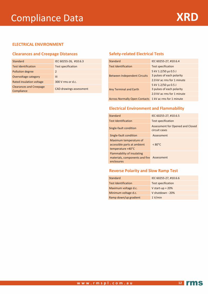
ELECTRICAL ENVIRONMENT
Clearances and Creepage Distances
Standard IEC 60255-26, #10.6.3
Test Identification Test specification
Pollution degree 2
Overvoltage category III
Rated insulation voltage 300 V rms or d.c.
Clearances and Creepage
Compliance CAD drawings assessment
Safety-related Electrical Tests
Standard IEC 60255-27, #10.6.4
Test Identification Test specification
Between Independent Circuits
5 kV 1.2/50 µs 0.5 J
3 pulses of each polarity
2.0 kV ac rms for 1 minute
Any Terminal and Earth
5 kV 1.2/50 µs 0.5 J
3 pulses of each polarity
2.0 kV ac rms for 1 minute
Across Normally Open Contacts 1 kV ac rms for 1 minute
Electrical Environment and Flammability
Standard IEC 60255-27, #10.6.5
Test Identification Test specification
Single-fault condition Assessment for Opened and Closed circuit cases
Single-fault condition Assessment
Maximum temperature of
accessible parts at ambient
temperature +40°C
< 80°C
Flammability of insulating
materials, components and fire enclosures
Assessment
Reverse Polarity and Slow Ramp Test
Standard IEC 60255-27, #10.6.6
Test Identification Test specification
Maximum voltage d.c. V start-up + 20%
Minimum voltage d.c. V shutdown - 20%
Ramp down/up gradient 1 V/min

13
w w w . r m s p l . c o m . a u
rms
Compliance Data XRD
ELECTROMAGNETIC COMPATIBILITY (EMC)
IMMUNITY
Electrostatic Discharge (ESD)
Standard IEC 60255-26, #7.2.3, Acceptance criterion B
Port Enclosure
Test Identification Test specification Variation
Air Discharge 8 kV ≤5%
Radiated Electromagnetic Field
Standard IEC 60255-26, #7.2.4, Acceptance criterion A
Port Enclosure
Test Identification Test specification Variation
Frequency sweep 10 V rms, 80 to 1000 MHz
1,400 to 2,700 MHz ≤5%
Spot frequencies 10 V rms, 80, 160, 380,
450, 900, 1,850 and 2,150 MHz ≤5%
Fast Transients (EFT)
Standard IEC 60255-26, #7.2.5, Acceptance criterion B
Port Input and Output ports
Test level Test specification Variation
Zone A 4 kV peak, 5/50 ns, 5 kHz ≤5%
Slow Damped Oscillatory Wave (HFD)
Standard IEC 60255-26, #7.2.6, Acceptance criterion B
Port Auxiliary Power Supply, Input and Output
Test Identification Test specification Variation
Common Mode 1 MHz 2.5 kV peak ≤5%
Differential Mode 1 MHz 1.0 kV peak ≤5%
Surge
Standard IEC 60255-26, #7.2.7, Acceptance criterion B
Port Auxiliary Power Supply, Input and Output
Test Identification Test specification Variation
Line-to-earth 4 kV peak ≤10%
Line-to-line 2 kV peak ≤10%
Conducted Disturbance Induced by RF Fields
Standard IEC 60255-26, #7.2.8, Acceptance criterion A
Port Auxiliary Power Supply, Input and Output
Test Identification Test specification Variation
Frequency sweep 10 V rms, 0.15 to 80 MHz ≤5%
Spot frequencies 10 V rms, 27 & 68 MHz ≤5%
Power Frequency Magnetic Field
Standard IEC 60255-26, #7.2.10
Port Enclosure only
Test Identification Test specification
Continuous ≥ 60 s 30 A/m - Acceptance criterion A
Short time 1 s to 3 s 300 A/m - Acceptance criterion B
14
Wiring Diagrams XRD
w w w . r m s p l . c o m . a u
rms
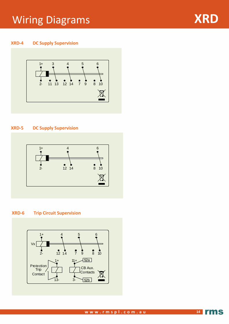
XRD-4 DC Supply Supervision
XRD-6 Trip Circuit Supervision
1+
1+ 11+ 52a
ProtectionTrip
Contact
Vx
CB Aux.
Contacts
4 5 6
2-
13- 3- 52b
1412 97 108
XRD-5 DC Supply Supervision
1+ 3 4 5 6
2- 11 12 7 9 8 1013 14
1+ 4 6
2- 12 8 1014

15
Wiring Diagrams XRD
w w w . r m s p l . c o m . a u
rms
Wiring Notes
Relays are shown in the non-powered (Alarm) condition.
Note the connection polarity for correct DC operation.
A wiring diagram is also printed on the front panel of the
relay module for easy reference in the field.
XRD-7 Trip Circuit Supervision
1+
1+ 11+ 52a
Protection
TripContact
Vx
CB Aux.
Contacts
4 6
2-
13- 3- 52b
1412 108

16
DeltaMounting and Dimensions
w w w . r m s p l . c o m . a u
rms
19 Inch Rack Mount Rear Connect (TBD-R Terminal Block)
Surface Mount Rear Connect (TBD-R Terminal Block)
19 inch rack mount 2U x 2U
rack mounting
Adapter plate for 2x units in a 2U x 4U rack frame
Adapter plate for 4x units in a 4U x 4U rack frame
94 30 45
Surface or Rail Mount Front Connect (TBD-F Terminal Block)
8765
Panel cut-out to mount surface rear connect base
Delta
17
Mounting and Dimensions
w w w . r m s p l . c o m . a u
rms
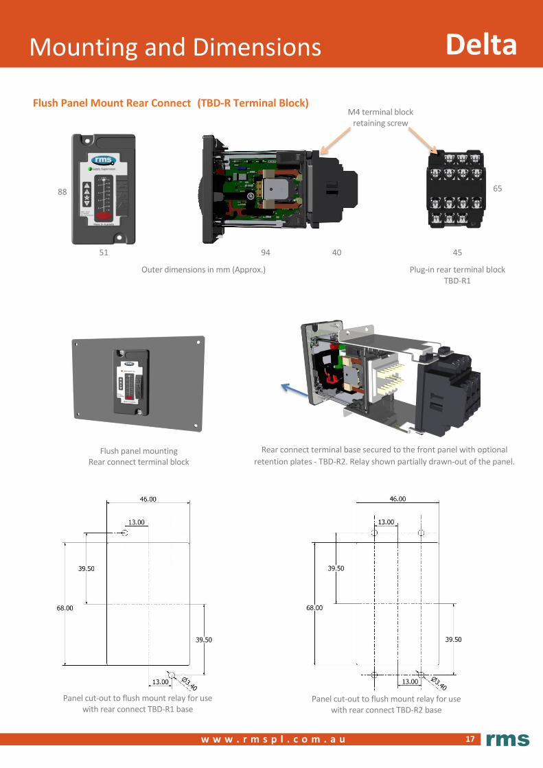
Flush Panel Mount Rear Connect (TBD-R Terminal Block)
88
51 94 40 45
65
Rear connect terminal base secured to the front panel with optional
retention plates - TBD-R2. Relay shown partially drawn-out of the panel.
Plug-in rear terminal block TBD-R1
Flush panel mounting Rear connect terminal block
M4 terminal block retaining screw
Panel cut-out to flush mount relay for use with rear connect TBD-R2 base
Panel cut-out to flush mount relay for use with rear connect TBD-R1 base
Outer dimensions in mm (Approx.)
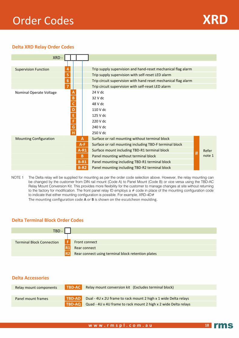
Order Codes
18
XRD
w w w . r m s p l . c o m . a u
rms
NOTE 1 The Delta relay will be supplied for mounting as per the order code selection above. However, the relay mounting can
be changed by the customer from DIN rail mount (Code A) to Panel Mount (Code B) or vice versa using the TBD-AC
Relay Mount Conversion Kit. This provides more flexibility for the customer to manage changes at site without returning
to the factory for modification. The front panel relay ID employs a # code in place of the mounting configuration code
to indicate that either mounting configuration is possible. For example, XRD-4D#
The mounting configuration code A or B is shown on the escutcheon moulding.
XRD -
Supervision Function 4 Trip supply supervision and hand-reset mechanical flag alarm
5 Trip supply supervision with self-reset LED alarm
6 Trip circuit supervision with hand reset mechanical flag alarm
7 Trip circuit supervision with self-reset LED alarm
Nominal Operate Voltage A 24 V dc
B 32 V dc
C 48 V dc
D 110 V dc
E 125 V dc
F 220 V dc
G 240 V dc
H 250 V dc
Mounting Configuration A Surface or rail mounting without terminal block
# Refer note 1
A-F Surface or rail mounting including TBD-F terminal block
A-R1 Surface mount including TBD-R1 terminal block
B Panel mounting without terminal block
B-R1 Panel mounting including TBD-R1 terminal block
B-R2 Panel mounting including TBD-R2 terminal block
TBD -
Terminal Block Connection F Front connect
R1 Rear connect
R2 Rear connect using terminal block retention plates
Relay mount components TBD-AC Relay mount conversion kit (Excludes terminal block)
Panel mount frames TBD-AD Dual - 4U x 2U frame to rack mount 2 high x 1 wide Delta relays
TBD-AQ Quad - 4U x 4U frame to rack mount 2 high x 2 wide Delta relays
Delta XRD Relay Order Codes
Compliance heading to go here
Delta Terminal Block Order Codes
Delta Accessories
R e l a y M o n i t o r i n g S y s t e m s P t y L t d 6 Anzed Court
Mulgrave, Victoria 3170
AUSTRALIA
Ph: +61 3 8544 1200
Fax +61 3 8544 1201
Sales: [email protected]
www.rmspl.com.au www.relays.com.au
ISO9001 Quality Accreditation RMS holds BSI (British Standards Institution) registration number FS
604860 for the certification of a quality system to AS/NZS ISO9001:2008.
Due to RMS continuous product improvement policy the information
contained in this document is subject to change without prior notice.
© 2017 Relay Monitoring Systems Pty Ltd ABN 76 052 484 483
Rel ay Mo n itor i ng Sys te m s Pt y L t d d es ig n, man ufa ct ur e an d ma rk et a w id e ra n ge o f e l ect r ic a l prot ec t io n an d con tro l pro d uct s for a p pl ica t io n o n h i g h vo lta g e powe r sy st em s. T h e com pa ny' s de p th o f man ufa ct ur i ng a n d e ng i n ee r i n g e xpe rt i se i s back e d u p b y m an y ye ars o f e xp er ie nc e s i nc e t he fo rma t io n o f i t s p re d ece s sor , Rel ays Pt y L t d (RPL) , i n 195 5. T hi s exp er i enc e comb i ne d wi t h a broa d b as e o f f ie l d prov e n p ro duc t t yp es e na bl e s RM S to se rv ice s p ec i f ic cu sto mer ne e ds b y pro d uc i n g re lay s on d ema n d an d wi th typ ica l l y sho rt l ea d t im e s.
www.rmspl.com.au