demand response and indoor unit operation - ausgrid/media/files/industry... · safety precautions...
TRANSCRIPT

Safety Precautions
Demand Response and Indoor Unit Operation
Before using this product, read these instructions thoroughly and keep this manual for future reference.
To prevent personal injury, injury to others, or property damage, read this manual carefully, and be sure to comply each safety notice. Incorrect operation or installation due to failure to follow the instructions may cause harm or damage, the seriousness of which is classified as follows:
This product is designed to be compatible with Air Conditioning Demand Response program.
Note:
DR mode Description of operation in this modeDR mode 1 Compressor off.
DR mode 2The air conditioner continues to cool or heat during the Demand Response event, but the electrical energy consumed by the air conditioner in a half hour period is not more than 50% of the total electrical energy that would be consumed if operating at the rated capacity in a half hour period.
DR mode 3The air conditioner continues to cool or heat during the Demand Response event, but the electrical energy consumed by the air conditioner in a half hour period is not more than 75% of the total electrical energy that would be consumed if operating at the rated capacity in a half hour period.
When your electricity supplier activates one of the following 3 DR modes, the air conditioner switches over to the appropriate operation, and the OPERATION indicator (green) on the indoor unit blinks to inform you it has been entered to the DR mode.
When the unit goes into a DR mode, it performs moderate operation though the cooling or heating effect may be reduced. You cannot override this function with changing the temperature setting by using the remote controller or other actions unless the unit finishes the function.
When the unit finishes the function, it will perform the operation that was previously performed before entering the DR mode.
AS4755.3 DRM1DRM2DRM3
compliant
Instructions for Users
WARNING
This unit contains no user-serviceable parts. Always consult authorized service personnel for repairing, installation, and relocation of this product. Improper installation or handling will cause leakage, electric shock, or fire.
WARNING
This mark warns of death or serious injury.
CAUTION
This mark warns of injury or damage to property.
This mark denotes an action that is PROHIBITED. This mark denotes an action that is COMPULSORY.
DEMAND RESPONSE-COMPATIBLE AIR CONDITIONER
INSTRUCTION MANUAL
When this air conditioner is connected to a DRED, and you have operational issues, contact your electricity supplier first to check whether they are activating any of the DR mode described above.If the air conditioner is under demand controlling, consult on the issues with your electricity supplier.If they are not demand controlling the air conditioner, refer to your warranty card for the contact details of Fujitsu General (AUST.) PTY LIMITED or visit our website : www.fujitsugeneral.com.au
To utilize the function, Demand Response (DR) adapter kit that interconnects your air conditioner and Demand Response Enabling Device (DRED) needs to be installed in your air conditioning system, and you need a separate arrangement.
OPERATION indicator (indoor unit)
Notes:・ Shape, number, and the arrangement of the indicators are unit-dependent.
Some indoor units may not have the indicators unless the optional control panel or IR receiver kit has been installed.
Blinking pattern and the interval are as follows:
The indicator will keep blinking until the unit finishes the function.
OFF (0.5 seconds)ON (4 seconds)
ON (0.5 seconds)OFF (0.5 seconds)
・
PART No. 9380829089
Stopping the operation of the air conditioner by using the remote controller or by OFF timer are valid in DR mode.If the timer operation is interfered by an interruption of power supply such as a blackout and the power supply is resumed, no indication of the DR mode is performed.During the DR mode, no indication of "filter sign" is performed.Powerful operation is performed within the operable range of the DR mode.
9380829089_OM_DR_AOTG24LFCC_En.indd 1 2012/07/10 9:22:22
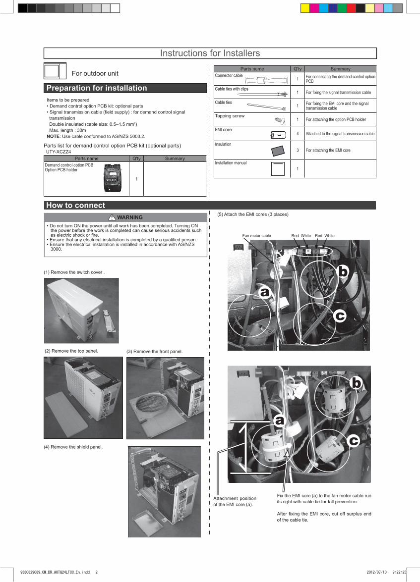
For outdoor unit
Instructions for Installers
How to connect
Preparation for installation
Parts name Q'ty SummaryDemand control option PCB Option PCB holder
1
WARNING
Items to be prepared:• Demand control option PCB kit: optional parts• Signal transmission cable (fi eld supply) : for demand control signal transmission Double insulated (cable size: 0.5–1.5 mm2) Max. length : 30mNOTE: Use cable conformed to AS/NZS 5000.2.
Parts list for demand control option PCB kit (optional parts)
• Do not turn ON the power until all work has been completed. Turning ON the power before the work is completed can cause serious accidents such as electric shock or fi re.• Ensure that any electrical installation is completed by a qualifi ed person.• Ensure the electrical installation is installed in accordance with AS/NZS 3000.
(4) Remove the shield panel.
(1) Remove the switch cover .
(2) Remove the top panel. (3) Remove the front panel.
Parts name Q'ty SummaryConnector cable
1 For connecting the demand control option PCB
Cable ties with clips1 For fi xing the signal transmission cable
Cable ties1 For fi xing the EMI core and the signal
transmission cable Tapping screw
1 For attaching the option PCB holder
EMI core4 Attached to the signal transmission cable
Insulation3 For attaching the EMI core
Installation manual1
(5) Attach the EMI cores (3 places)
Fix the EMI core (a) to the fan motor cable run its right with cable tie for fall prevention.
After fi xing the EMI core, cut off surplus end of the cable tie.
UTY-XCZZ4
Red White Red White
ab
c
a
b
c
Attachment position of the EMI core (a).
Fan motor cable
9380829089_OM_DR_AOTG24LFCC_En.indd 2 2012/07/10 9:22:25
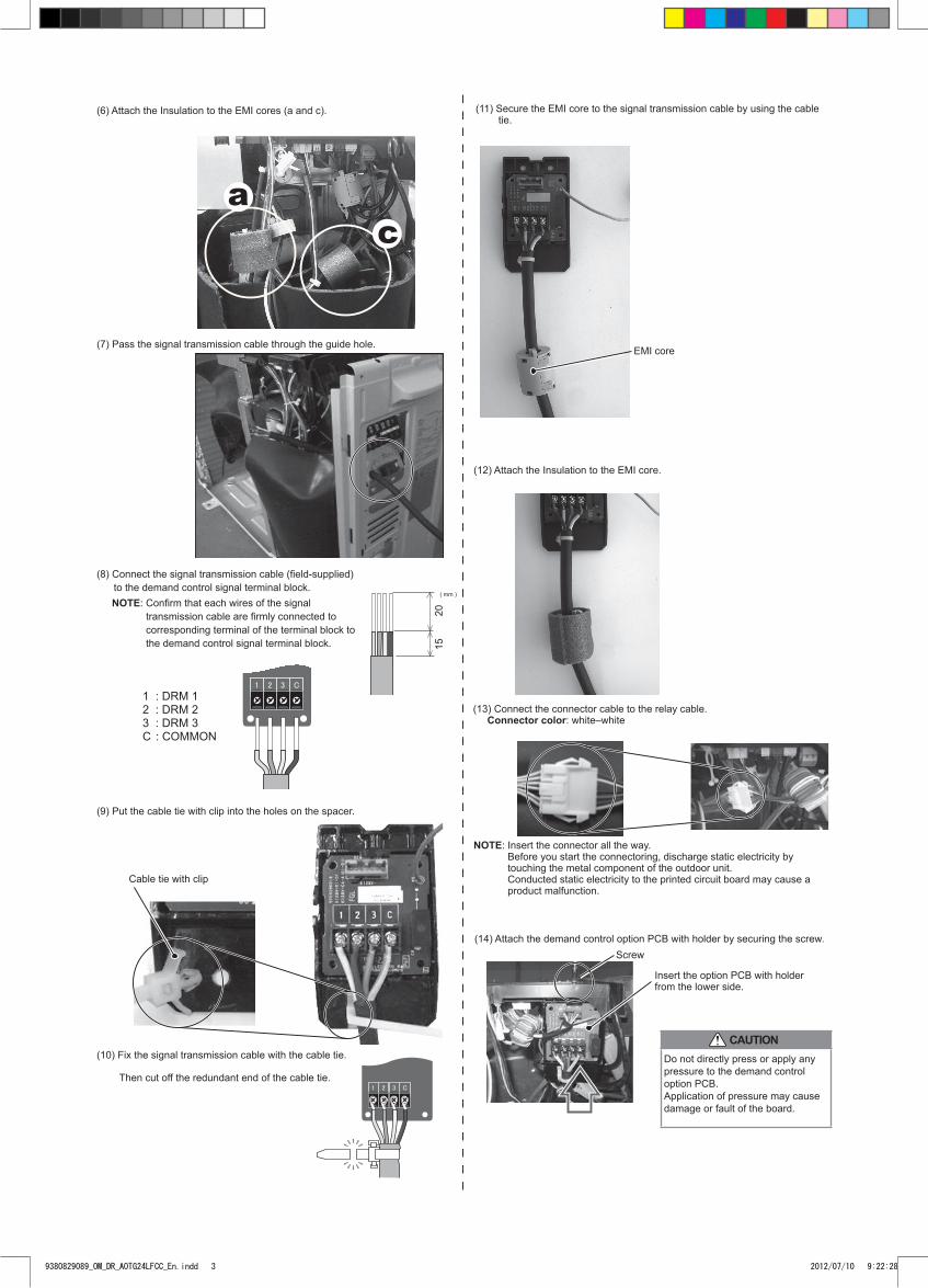
CAUTION
Screw
Cable tie with clip
(11) Secure the EMI core to the signal transmission cable by using the cable tie.
EMI core
(9) Put the cable tie with clip into the holes on the spacer.
(10) Fix the signal transmission cable with the cable tie.
Then cut off the redundant end of the cable tie.
(13) Connect the connector cable to the relay cable. Connector color: white–white
(14) Attach the demand control option PCB with holder by securing the screw.
Do not directly press or apply any pressure to the demand control option PCB.Application of pressure may cause damage or fault of the board.
NOTE: Insert the connector all the way. Before you start the connectoring, discharge static electricity by touching the metal component of the outdoor unit. Conducted static electricity to the printed circuit board may cause a product malfunction.
Insert the option PCB with holder from the lower side.
1 : DRM 12 : DRM 23 : DRM 3C : COMMON
2015
( mm )
(8) Connect the signal transmission cable (fi eld-supplied) to the demand control signal terminal block.
NOTE: Confi rm that each wires of the signal transmission cable are fi rmly connected to corresponding terminal of the terminal block to the demand control signal terminal block.
(7) Pass the signal transmission cable through the guide hole.
(12) Attach the Insulation to the EMI core.
(6) Attach the Insulation to the EMI cores (a and c).
ac
9380829089_OM_DR_AOTG24LFCC_En.indd 3 2012/07/10 9:22:28
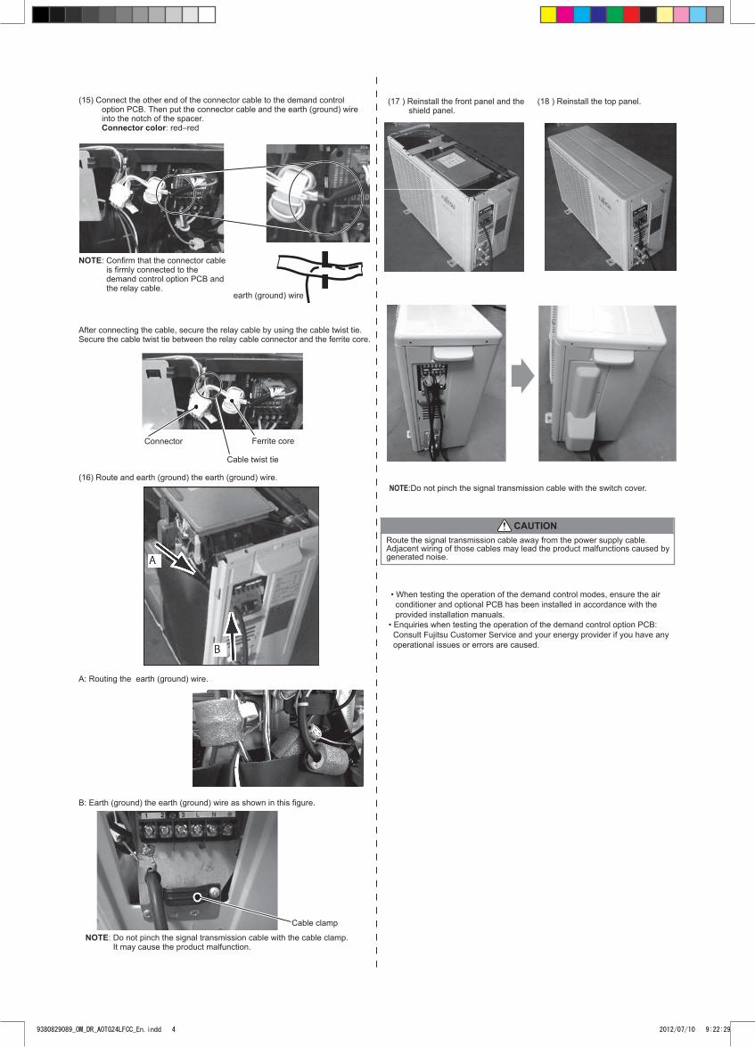
Cable clamp
NOTE: Do not pinch the signal transmission cable with the cable clamp. It may cause the product malfunction.
• When testing the operation of the demand control modes, ensure the air conditioner and optional PCB has been installed in accordance with the provided installation manuals.• Enquiries when testing the operation of the demand control option PCB: Consult Fujitsu Customer Service and your energy provider if you have any operational issues or errors are caused.
CAUTIONRoute the signal transmission cable away from the power supply cable.Adjacent wiring of those cables may lead the product malfunctions caused bygenerated noise.
After connecting the cable, secure the relay cable by using the cable twist tie.Secure the cable twist tie between the relay cable connector and the ferrite core.
earth (ground) wire
Connector Ferrite core
Cable twist tie
(15) Connect the other end of the connector cable to the demand control option PCB. Then put the connector cable and the earth (ground) wire into the notch of the spacer. Connector color: red–red
NOTE: Confi rm that the connector cable is fi rmly connected to the demand control option PCB and the relay cable.
(16) Route and earth (ground) the earth (ground) wire.
A: Routing the earth (ground) wire.
B: Earth (ground) the earth (ground) wire as shown in this fi gure.
(17 ) Reinstall the front panel and the shield panel.
(18 ) Reinstall the top panel.
(19) Reinstall the switch cover.
NOTE:Do not pinch the signal transmission cable with the switch cover.
(19) Reinstall the switch cover.
9380829089_OM_DR_AOTG24LFCC_En.indd 4 2012/07/10 9:22:29