demonstrating semantic interoperability of …1 demonstrating semantic interoperability of...
TRANSCRIPT
1
Demonstrating Semantic Interoperability of Diagnostic Models via AI-ESTATE
John W. Sheppard, Stephyn G. W. Butcher, Patrick J. Donnelly, Benjamin R. Mitchell Department of Computer Science, The Johns Hopkins University
3400 North Charles Street Baltimore, MD 21218
410-516-6115 [email protected]
Abstract—The Institute for Electrical and Electronics Engineers (IEEE), through its Standards Coordinating Committee 20 (SCC20), is developing interface standards focusing on Automatic Test System-related elements in cooperation with a Department of Defense (DoD) initiative to define, demonstrate, and mandate such standards. One of these standards—IEEE Std 1232-2002 Artificial Intelligence Exchange and Service Tie to All Test Environments (AI-ESTATE)—has been chosen for demonstration prior to mandate. In this paper, we discuss the results of the first phase of the AI-ESTATE demonstration, focusing on semantic interoperability of diagnostic models. The results of this demonstration successfully showed the effectiveness of semantic modeling in information exchange. In addition, the engineering burden was demonstrated to be manageable: all applications were constructed in less than four months by three graduate students working part time.1,2
TABLE OF CONTENTS
1. INTRODUCTION.................................................................1 2. DEMONSTRATING AI-ESTATE.......................................2 3. INFORMATION MODELING IN AI-ESTATE ....................3 4. DEMONSTRATION PLAN ...................................................5 5. SCHEMA DEVELOPMENT..................................................6 6. APPLICATION DEVELOPMENT .........................................7 7. THE DEMONSTRATION .....................................................9 8. CONCLUSIONS ................................................................12 ACKNOWLEDGMENTS ........................................................12 REFERENCES ......................................................................12 BIOGRAPHIES .....................................................................13
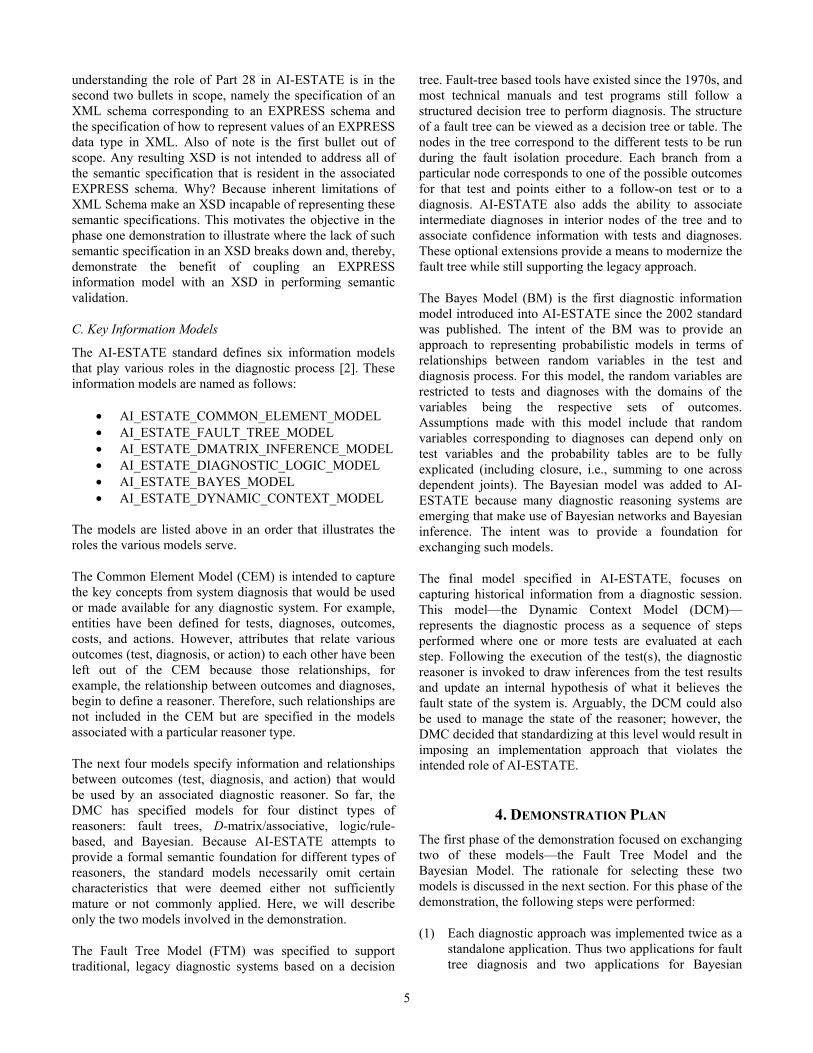
1. INTRODUCTION The Department of Defense (DoD) has established a partnership between government, industry and academia to address architectural design and standardization issues for automatic test systems (ATS). This DoD ATS Framework Working Group is focusing on defining an information framework and identifying standards for next-generation ATS. The principal requirement to be satisfied by the framework and associated standards is providing an open architecture for ATS to reduce overall cost of development and ownership for resulting families of standards. Based on
1 1 978-1-4244-2622-5/09/$25.00 © 2009 IEEE 2 IEEEAC Paper #1570, Version 10, Updated November 26, 2008
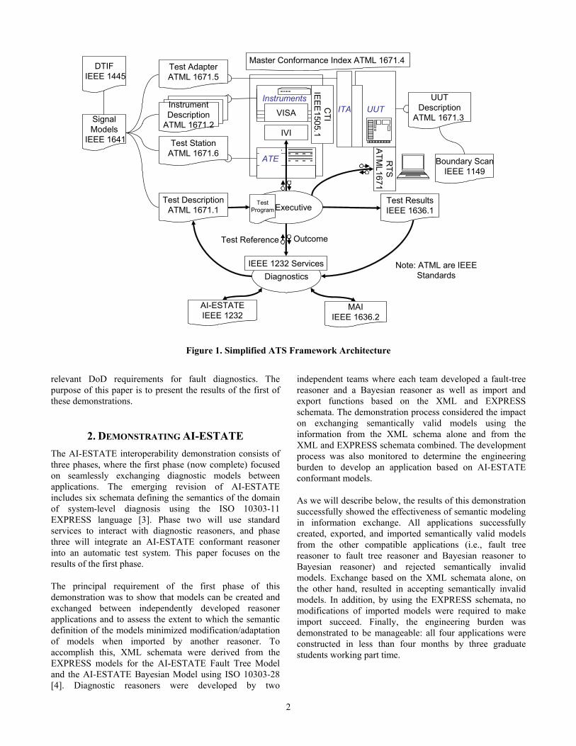
work in the 1990s when the ATS Research and Development Integrated Product Team defined a set of “critical interfaces” for ATS, the current working group has been selecting, supporting the development of, and demonstrating commercial standards to be used in ATS with the intent of, ultimately, mandating these standards in future ATS procurement programs. The current ATS Framework, identifying relevant standards, is shown in Figure 1.
Of specific interest in the work reported here are the DIAD (diagnostic data) and DIAS (diagnostic service) interfaces. Currently, these interfaces are defined as follows:
• Diagnostic Data is that information which supports the investigation and analysis of the cause or nature of a condition, situation, or problem through all phases of the system life cycle.
• Diagnostic Services are those standardized interfaces that facilitate transmission, conversion, and retrieval of diagnostic data for utilization in the maintenance process. These services link results obtained from the execution of a test with a diagnostic process that utilizes these results and suggests conclusions or additional actions that are required.
In 1976, the IEEE established the Standards Coordinating Committee 20 (SCC20) for purposes of standardizing on the Abbreviated Test Language for All Systems (ATLAS). Since then, SCC20 has expanded its scope to develop standards for larger system-level test and diagnostic related systems. In 1989, the IEEE approved a project authorization request (PAR) for SCC20 to develop a new standard focusing on diagnostic systems that use techniques from the maturing field of artificial intelligence—the Artificial Intelligence Exchange and Service Tie to All Test Environments (AI-ESTATE) standard under project P1232. In 1995, SCC20 approved and published the AI-ESTATE standard, IEEE Std 1232-1995, and in 2002, the standard was updated [1].
The AI-ESTATE is undergoing a major revision to update several standard diagnostic models and to define data and software interfaces consistent with modern software architectures [2]. Prior to mandating the revised AI-ESTATE standard, several demonstrations are being performed to show that the standard is capable of meeting
2
relevant DoD requirements for fault diagnostics. The purpose of this paper is to present the results of the first of these demonstrations.
2. DEMONSTRATING AI-ESTATE The AI-ESTATE interoperability demonstration consists of three phases, where the first phase (now complete) focused on seamlessly exchanging diagnostic models between applications. The emerging revision of AI-ESTATE includes six schemata defining the semantics of the domain of system-level diagnosis using the ISO 10303-11 EXPRESS language [3]. Phase two will use standard services to interact with diagnostic reasoners, and phase three will integrate an AI-ESTATE conformant reasoner into an automatic test system. This paper focuses on the results of the first phase.
The principal requirement of the first phase of this demonstration was to show that models can be created and exchanged between independently developed reasoner applications and to assess the extent to which the semantic definition of the models minimized modification/adaptation of models when imported by another reasoner. To accomplish this, XML schemata were derived from the EXPRESS models for the AI-ESTATE Fault Tree Model and the AI-ESTATE Bayesian Model using ISO 10303-28 [4]. Diagnostic reasoners were developed by two
independent teams where each team developed a fault-tree reasoner and a Bayesian reasoner as well as import and export functions based on the XML and EXPRESS schemata. The demonstration process considered the impact on exchanging semantically valid models using the information from the XML schema alone and from the XML and EXPRESS schemata combined. The development process was also monitored to determine the engineering burden to develop an application based on AI-ESTATE conformant models.
As we will describe below, the results of this demonstration successfully showed the effectiveness of semantic modeling in information exchange. All applications successfully created, exported, and imported semantically valid models from the other compatible applications (i.e., fault tree reasoner to fault tree reasoner and Bayesian reasoner to Bayesian reasoner) and rejected semantically invalid models. Exchange based on the XML schemata alone, on the other hand, resulted in accepting semantically invalid models. In addition, by using the EXPRESS schemata, no modifications of imported models were required to make import succeed. Finally, the engineering burden was demonstrated to be manageable: all four applications were constructed in less than four months by three graduate students working part time.
Executive
Diagnostics
CTI
IEEE1505.1
IEEE 1232 Services
UUTITAInstruments
RTS
ATM
L1671
SignalModels
IEEE 1641
Test AdapterATML 1671.5
InstrumentDescription
ATML 1671.2
Test StationATML 1671.6
Test DescriptionATML 1671.1
Test ResultsIEEE 1636.1
UUTDescription
ATML 1671.3
MAIIEEE 1636.2
Master Conformance Index ATML 1671.4
AI-ESTATEIEEE 1232
InstrumentsInstrumentsInstruments
VISA
TestProgram
Note: ATML are IEEEStandards
DTIFIEEE 1445
Boundary ScanIEEE 1149
IVI
ATE
OutcomeTest Reference
Figure 1. Simplified ATS Framework Architecture
3
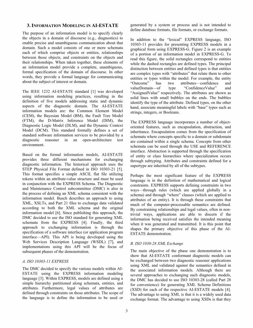
3. INFORMATION MODELING IN AI-ESTATE The purpose of an information model is to specify clearly the objects in a domain of discourse (e.g., diagnostics) to enable precise and unambiguous communication about that domain. Such a model consists of one or more schemata each of which comprise objects or entities, relationships between those objects, and constraints on the objects and their relationships. When taken together, these elements of an information model provide a complete, unambiguous, formal specification of the domain of discourse. In other words, they provide a formal language for communicating about the subject of interest or domain.
The IEEE 1232 AI-ESTATE standard [1] was developed using information modeling practices, resulting in the definition of five models addressing static and dynamic aspects of the diagnostic domain. The AI-ESTATE information models are: the Common Element Model (CEM), the Bayesian Model (BM), the Fault Tree Model (FTM), the D-Matrix Inference Model (DIM), the Diagnostic Logic Model (DLM), and the Dynamic Context Model (DCM). This standard formally defines a set of standard software information services to be provided by a diagnostic reasoner in an open-architecture test environment.
Based on the formal information models, AI-ESTATE provides three different mechanisms for exchanging diagnostic information. The historical approach uses the STEP Physical File Format defined in ISO 10303-21 [5]. This format specifies a simple ASCII, flat file utilizing tokens within an attribute-value structure and must be used in conjunction with the EXPRESS Schema. The Diagnostic and Maintenance Control subcommittee (DMC) is also in the process of defining an XML schema consistent with the information model. Busch describes an approach to using XML, XSLTs, and Part 21 files to exchange data validated according to both the XML schema and the original information model [6]. Since publishing this approach, the DMC decided to use the ISO standard for generating XML schemata from the EXPRESS [4]. Finally, the third approach to exchanging information is through the specification of a software interface (or application program interface—API). This API is being developed using the Web Services Description Language (WSDL) [7], and implementations using this API will be the focus of subsequent phases of the demonstration.
A. ISO 10303-11 EXPRESS
The DMC decided to specify the various models within AI-ESTATE using the EXPRESS information modeling language [3]. Within EXPRESS, models are defined using a simple hierarchy partitioned along schemata, entities, and attributes. Furthermore, legal values of attributes are defined through constraints on those attributes. The scope of the language is to define the information to be used or
generated by a system or process and is not intended to define database formats, file formats, or exchange formats.
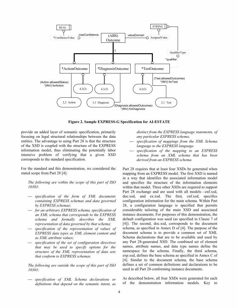
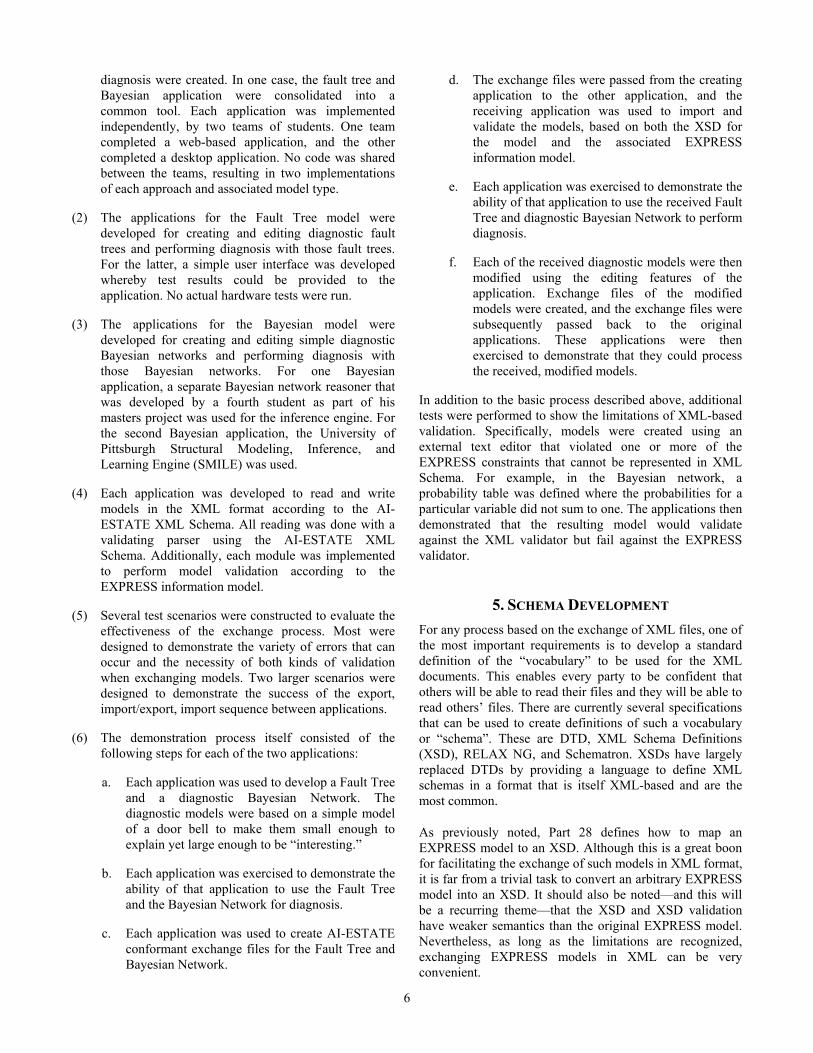
In addition to the “lexical” EXPRESS language, ISO 10303-11 provides for presenting EXPRESS models in a graphical form using EXPRESS-G. Figure 2 is an example of a portion of an information model in EXPRESS-G. To read this figure, the solid rectangles correspond to entities while the dashed rectangles are defined types. The principal distinction between entities and defined types is that entities are complex types with “attributes” that relate them to other entities or types within the model. For example, the entity “Outcome” has two attributes—confidence and valueDomain—of type “ConfidenceValue” and “AssignedValue” respectively. The attributes are shown as solid lines with small bubbles on the ends. The bubbles identify the type of the attribute. Defined types, on the other hand, associate meaningful labels with “base” types such as strings, integers, or Booleans.
The EXPRESS language incorporates a number of object-oriented features, such as encapsulation, abstraction, and inheritance. Encapsulation comes from the specification of schemata where concepts specific to a domain or subdomain are contained within a single schema. Concepts from other schemata can be used through the USE and REFERENCE interface. Abstraction is supported through the specification of entity or class hierarchies where specialization occurs through subtyping. Attributes and constraints defined for a supertype are inherited by all of the subtypes.
Perhaps the most significant feature of the EXPRESS language is in the definition of mathematical and logical constraints. EXPRESS supports defining constraints in two ways—through rules (which are applied globally in a schema) and through “where” clauses (which are applied to attributes of an entity). It is through these constraints that much of the computer-processable semantics are defined. By constraining relationships and legal values, often in non-trivial ways, applications are able to discern if the information being received satisfies the intended meaning when it was generated and transmitted. It is this point that shapes the primary objective of this phase of the AI-ESTATE demonstration.
B. ISO 1030-28 XML Exchange
The main objective of the phase one demonstration is to show that AI-ESTATE conformant diagnostic models can be exchanged between two diagnostic reasoner applications using XML and validated against the semantics defined in the associated information models. Although there are several approaches to exchanging such diagnostic models, the DMC has decided to use ISO 10303-28 (called Part 28 for convenience) for generating XML Schema Definitions (XSD) for each of the respective AI-ESTATE models [4]. The advantage to using XML is that it is a widely used data exchange format. The advantage to using XSDs is that they
4
provide an added layer of semantic specification, primarily focusing on legal structural relationships between the data entities. The advantage to using Part 28 is that the structure of the XSD is coupled with the structure of the EXPRESS information model, thus eliminating the potentially labor intensive problem of verifying that a given XSD corresponds to the standard specification.
For the standard and this demonstration, we considered the stated scope from Part 28 [4]:
The following are within the scope of this part of ISO 10303:
⎯ specification of the form of XML documents containing EXPRESS schemas and data governed by EXPRESS schemas;
⎯ for an arbitrary EXPRESS schema, specification of an XML schema that corresponds to the EXPRESS schema and formally describes the XML representation of data governed by that schema;
⎯ specification of the representation of values of EXPRESS data types as XML element content and as XML attribute values;
⎯ specification of the set of configuration directives that may be used to specify options for the structure of the XML representation of data sets that conform to EXPRESS schemas.
The following are outside the scope of this part of ISO 10303:
⎯ specification of XML Schema declarations or definitions that depend on the semantic intent, as
distinct from the EXPRESS language statements, of any particular EXPRESS schema;
⎯ specification of mappings from the XML Schema language to the EXPRESS language.
⎯ specification of the mapping to an EXPRESS schema from an XML schema that has been derived from an EXPRESS schema.
Part 28 requires that at least four XSDs be generated when mapping from an EXPRESS model. The first XSD is named in a way that identifies the associated information model and specifies the structure of the information elements within that model. Three other XSDs are required to support Part 28 exchange and are used with all models—cnf.xsd, doc.xsd, and ex.xsd. The first, cnf.xsd, specifies configuration information for the main schema. Within Part 28, a configuration language is specified that permits considerable tailoring of the main XSD and associated instance documents. For purposes of this demonstration, the default configuration was used (as specified in Clause 7 of [4]). The second, doc.xsd, corresponds to the document schema, as specified in Annex D of [4]. The purpose of the document schema is to provide a common set of XML Schema declarations that are to be available and used by any Part 28-generated XSD. The combined set of element names, attribute names, and data type names define the namespace for the schema. Finally, the third schema, exp.xsd, defines the base schema as specified in Annex C of [4]. Similar to the document schema, the base schema defines a set of common definitions and declarations to be used in all Part 28-conforming instance documents.
As described below, all four XSDs were generated for each of the demonstration information models. Key to
(Diagnosis.allowedOutcomes)*(INV) forDiagnosis
3,3 Diagnosis
*DiagnosisOutcome
(ABS)Outcome
1
*TestOutcome
*qualifier
QualifierType
STRING
(Test.allowedOutcomes)*(INV) forTest
2,1 Test
(Action.allowedStatus)*(INV) forAction
2,2 Action
*ActionOutcome
valueDomain AssignedValue
4,3(2) 4,2(2)
maxConfidence *ConfidenceValue
REAL
4,1(3)
Figure 2. Sample EXPRESS-G Specification for AI-ESTATE
5
understanding the role of Part 28 in AI-ESTATE is in the second two bullets in scope, namely the specification of an XML schema corresponding to an EXPRESS schema and the specification of how to represent values of an EXPRESS data type in XML. Also of note is the first bullet out of scope. Any resulting XSD is not intended to address all of the semantic specification that is resident in the associated EXPRESS schema. Why? Because inherent limitations of XML Schema make an XSD incapable of representing these semantic specifications. This motivates the objective in the phase one demonstration to illustrate where the lack of such semantic specification in an XSD breaks down and, thereby, demonstrate the benefit of coupling an EXPRESS information model with an XSD in performing semantic validation.
C. Key Information Models
The AI-ESTATE standard defines six information models that play various roles in the diagnostic process [2]. These information models are named as follows:
• AI_ESTATE_COMMON_ELEMENT_MODEL • AI_ESTATE_FAULT_TREE_MODEL • AI_ESTATE_DMATRIX_INFERENCE_MODEL • AI_ESTATE_DIAGNOSTIC_LOGIC_MODEL • AI_ESTATE_BAYES_MODEL • AI_ESTATE_DYNAMIC_CONTEXT_MODEL
The models are listed above in an order that illustrates the roles the various models serve.
The Common Element Model (CEM) is intended to capture the key concepts from system diagnosis that would be used or made available for any diagnostic system. For example, entities have been defined for tests, diagnoses, outcomes, costs, and actions. However, attributes that relate various outcomes (test, diagnosis, or action) to each other have been left out of the CEM because those relationships, for example, the relationship between outcomes and diagnoses, begin to define a reasoner. Therefore, such relationships are not included in the CEM but are specified in the models associated with a particular reasoner type.
The next four models specify information and relationships between outcomes (test, diagnosis, and action) that would be used by an associated diagnostic reasoner. So far, the DMC has specified models for four distinct types of reasoners: fault trees, D-matrix/associative, logic/rule-based, and Bayesian. Because AI-ESTATE attempts to provide a formal semantic foundation for different types of reasoners, the standard models necessarily omit certain characteristics that were deemed either not sufficiently mature or not commonly applied. Here, we will describe only the two models involved in the demonstration.
The Fault Tree Model (FTM) was specified to support traditional, legacy diagnostic systems based on a decision
tree. Fault-tree based tools have existed since the 1970s, and most technical manuals and test programs still follow a structured decision tree to perform diagnosis. The structure of a fault tree can be viewed as a decision tree or table. The nodes in the tree correspond to the different tests to be run during the fault isolation procedure. Each branch from a particular node corresponds to one of the possible outcomes for that test and points either to a follow-on test or to a diagnosis. AI-ESTATE also adds the ability to associate intermediate diagnoses in interior nodes of the tree and to associate confidence information with tests and diagnoses. These optional extensions provide a means to modernize the fault tree while still supporting the legacy approach.
The Bayes Model (BM) is the first diagnostic information model introduced into AI-ESTATE since the 2002 standard was published. The intent of the BM was to provide an approach to representing probabilistic models in terms of relationships between random variables in the test and diagnosis process. For this model, the random variables are restricted to tests and diagnoses with the domains of the variables being the respective sets of outcomes. Assumptions made with this model include that random variables corresponding to diagnoses can depend only on test variables and the probability tables are to be fully explicated (including closure, i.e., summing to one across dependent joints). The Bayesian model was added to AI-ESTATE because many diagnostic reasoning systems are emerging that make use of Bayesian networks and Bayesian inference. The intent was to provide a foundation for exchanging such models.
The final model specified in AI-ESTATE, focuses on capturing historical information from a diagnostic session. This model—the Dynamic Context Model (DCM)—represents the diagnostic process as a sequence of steps performed where one or more tests are evaluated at each step. Following the execution of the test(s), the diagnostic reasoner is invoked to draw inferences from the test results and update an internal hypothesis of what it believes the fault state of the system is. Arguably, the DCM could also be used to manage the state of the reasoner; however, the DMC decided that standardizing at this level would result in imposing an implementation approach that violates the intended role of AI-ESTATE.
4. DEMONSTRATION PLAN The first phase of the demonstration focused on exchanging two of these models—the Fault Tree Model and the Bayesian Model. The rationale for selecting these two models is discussed in the next section. For this phase of the demonstration, the following steps were performed:
(1) Each diagnostic approach was implemented twice as a standalone application. Thus two applications for fault tree diagnosis and two applications for Bayesian
6
diagnosis were created. In one case, the fault tree and Bayesian application were consolidated into a common tool. Each application was implemented independently, by two teams of students. One team completed a web-based application, and the other completed a desktop application. No code was shared between the teams, resulting in two implementations of each approach and associated model type.
(2) The applications for the Fault Tree model were developed for creating and editing diagnostic fault trees and performing diagnosis with those fault trees. For the latter, a simple user interface was developed whereby test results could be provided to the application. No actual hardware tests were run.
(3) The applications for the Bayesian model were developed for creating and editing simple diagnostic Bayesian networks and performing diagnosis with those Bayesian networks. For one Bayesian application, a separate Bayesian network reasoner that was developed by a fourth student as part of his masters project was used for the inference engine. For the second Bayesian application, the University of Pittsburgh Structural Modeling, Inference, and Learning Engine (SMILE) was used.
(4) Each application was developed to read and write models in the XML format according to the AI-ESTATE XML Schema. All reading was done with a validating parser using the AI-ESTATE XML Schema. Additionally, each module was implemented to perform model validation according to the EXPRESS information model.
(5) Several test scenarios were constructed to evaluate the effectiveness of the exchange process. Most were designed to demonstrate the variety of errors that can occur and the necessity of both kinds of validation when exchanging models. Two larger scenarios were designed to demonstrate the success of the export, import/export, import sequence between applications.
(6) The demonstration process itself consisted of the following steps for each of the two applications:
a. Each application was used to develop a Fault Tree and a diagnostic Bayesian Network. The diagnostic models were based on a simple model of a door bell to make them small enough to explain yet large enough to be “interesting.”
b. Each application was exercised to demonstrate the ability of that application to use the Fault Tree and the Bayesian Network for diagnosis.
c. Each application was used to create AI-ESTATE conformant exchange files for the Fault Tree and Bayesian Network.
d. The exchange files were passed from the creating application to the other application, and the receiving application was used to import and validate the models, based on both the XSD for the model and the associated EXPRESS information model.
e. Each application was exercised to demonstrate the ability of that application to use the received Fault Tree and diagnostic Bayesian Network to perform diagnosis.
f. Each of the received diagnostic models were then modified using the editing features of the application. Exchange files of the modified models were created, and the exchange files were subsequently passed back to the original applications. These applications were then exercised to demonstrate that they could process the received, modified models.
In addition to the basic process described above, additional tests were performed to show the limitations of XML-based validation. Specifically, models were created using an external text editor that violated one or more of the EXPRESS constraints that cannot be represented in XML Schema. For example, in the Bayesian network, a probability table was defined where the probabilities for a particular variable did not sum to one. The applications then demonstrated that the resulting model would validate against the XML validator but fail against the EXPRESS validator.
5. SCHEMA DEVELOPMENT For any process based on the exchange of XML files, one of the most important requirements is to develop a standard definition of the “vocabulary” to be used for the XML documents. This enables every party to be confident that others will be able to read their files and they will be able to read others’ files. There are currently several specifications that can be used to create definitions of such a vocabulary or “schema”. These are DTD, XML Schema Definitions (XSD), RELAX NG, and Schematron. XSDs have largely replaced DTDs by providing a language to define XML schemas in a format that is itself XML-based and are the most common.
As previously noted, Part 28 defines how to map an EXPRESS model to an XSD. Although this is a great boon for facilitating the exchange of such models in XML format, it is far from a trivial task to convert an arbitrary EXPRESS model into an XSD. It should also be noted—and this will be a recurring theme—that the XSD and XSD validation have weaker semantics than the original EXPRESS model. Nevertheless, as long as the limitations are recognized, exchanging EXPRESS models in XML can be very convenient.
7
Fortunately, we were able to sidestep the difficulty of creating a Part 28 compliant XSD from the AI-ESTATE EXPRESS model specification. Instead of creating the XSDs by hand, we were able to use a tool called Jen-X that generates “default” XSDs (where “default” is defined by the standard) from a long form EXPRESS model [8].
To create the XSDs required for this project, we first took the simplified AI-ESTATE Fault Tree and Bayes Network models and created long form versions of them. In other words, the Common Element Model was physically imported into each of the models. Second, we ran the EXPRESS models through the Jen-X tool to generate the XSDs. These two XSDs were the ones used for the demonstration project.
One additional tool proved to be very useful for the project. DocFlex-XML generates HTML documentation (like JavaDoc) for XSD files. This tool proved invaluable for documenting the automatically generated XSDs without resorting to commercial tools such as XMLSpy.
6. APPLICATION DEVELOPMENT Two separate teams were responsible for application development. Each team was tasked to independently implement two applications: a Fault Tree diagnostic reasoner and a Bayes Network diagnostic reasoner. The specifications for each application were as follows:
(1) Each application should be able to create, save and edit the implemented diagnostic reasoning model (Fault Tree or Bayesian Network).
(2) Each application should be able to use the model for diagnosis including the recording and display of test results and ambiguity groups. Display features should be appropriate to the model implemented.
(3) Each application should be able to validate and import a model from an XML file. The model should be validated using both the XSD and those constraints in the EXPRESS information model that could not be expressed in the XSD.
(4) Each application should be able to export valid models with validation including both XSD and EXPRESS constraint checking.
Programming languages, frameworks and other such architectural details were left up to the individual teams. The project leader stood in for the “customer” when specification and feature questions arose.
A. Team A Application
Team A’s application is written entirely in the Java programming language. All components were developed
expressly for this application or use standard packages of the Java 6 API, with the sole exception of the Bayesian inference engine. This engine, which was created by another graduate student as an independent project, is also written in Java.
The application has two distinct modes of operation: the first for creating, editing, and evaluating FTMs and the second for creating, editing, and evaluating BMs. Each mode has a Graphical User Interface (GUI) for creating and editing the diagnostic models, as well as a separate interface for performing diagnostic evaluation of the current diagnostic model. The interface for entering test results for diagnosis requires manual data input by the user, as does the interface for the creation and modification of diagnostic models.
The EXPRESS compliant XML exchange file format is used as the application's native file format. Therefore, any time a model is saved to or loaded from disk, it must be converted from the internal data model of the application to the standard XML exchange format, or vice-versa. When an XML file is loaded from disk, the application checks the model against both the XSD constraints and the EXPRESS semantic constraints. In the event a model fails validation, the application generates an error message explaining which constraint has been violated and whether it is an XSD-based constraint or a higher-level EXPRESS constraint.
Furthermore, the application can be set to ignore errors in this validation step. This allows models which are correct but incomplete, such as a BM in which the probability tables have not yet been populated, to be loaded so that the model can be completed. The application will still generate validation error messages in this mode, but will continue trying to load the model in spite of the errors. Truly malformed models will still fail to load if the data in the file cannot be mapped to the data structures expected by the standard.
The application contains three principal components: the graphical user interface, the data model, and the XML parser and validator. The data model is a set of Java classes that contain information about the active diagnostic model. Because we chose to use the XML exchange format as our native file format, the structure of the data model closely parallels the model format defined by the exchange standard. This means that there are several classes in the data model that are not directly interacted with by the user via the GUI, but it also means that the translation to and from XML is a very natural one. In particular, writing XML files is a straightforward process of recursive traversal of the data model in memory, with each class possessing the knowledge of how to translate itself into AI-ESTATE conformant XML.
The GUI is composed of a set of classes inheriting from the standard Java Swing package. It does not contain a separate
8
data model, but rather communicates with the underlying data model directly, passing messages to the data model both to modify the data based on user input and to update the GUI display based on the current state of the model.
The XML parser/validator makes use of the standard Java Document Object Model (DOM) XML parser both for reading the file into memory and for the XSD based validation. The DOM objects are then parsed by code specific to the application that extracts semantic information based on the AI-ESTATE specification and then creates new objects in the application's data model with the same semantic content. Application specific code also validates any EXPRESS constraints which are not checked by the XSD; as mentioned earlier, this includes verifying that the probability tables are well formed by ensuring that all rows are the same length, that the length is correct given the set of dependencies, and ensuring that each row sums to one.
While these tests had to be hand written (as opposed to the XSD, which was extracted from the EXPRESS standard in an automated fashion), the engineering burden imposed was fairly minor. This is due to the fact that many constraints are already checked by the XSD, while others do not need to be checked, as they are true by construction (e.g., the standard has EXPRESS constraints to check that parent-child relationships are bi-directional, but since the application creates the links, it is impossible for a uni-directional relationship to exist. Thus, this constraint and a number of others like it did not need to be explicitly tested). Only a small number of tests actually had to be written by hand, and most of them were quite simple, taking only a few lines of code to perform.
B. Team B Application
Team B also developed a consolidated application that could handle both types of models, Fault Trees and Bayesian Networks. The application is written as a networked web application. The client consists of an Adobe Flash application written using the Flex software development kit (SDK). Flex allows for the creation of Flash applications using a combination of ActionScript and compilable XML to describe the user interface and provide behavior. The resulting application can be run in any browser that supports Flash 9.
The server is implemented using Ruby on Rails, a popular web application framework. In this particular case, Rails is run under jRuby, the implementation of Ruby for the Java Virtual Machine. The main advantage to running Rails under jRuby is that jRuby provides full access to Java-based libraries from inside the Ruby language and thus Rails. This is an important design consideration because the Bayesian Network inference library used was the SMILE library written by the University of Pittsburgh. Although SMILE is a C++ library, a Java Native Interface (JNI) wrapper is also
provided permitting access to the library inside Java. JRuby provides access to that from inside Rails’s Ruby code.
Communication between the client and server is mediated using Adobe’s Action Message Format (AMF) for binary object serialization. Using binary serialization required writing all data models in both Ruby and ActionScript. Although serialization and deserialization are handled automatically by the client, server-side serialization and deserialization is accomplished using the RubyAMF component. On the server-side, all models are stored using the YAML Ain’t Markup Language (YAML) format to mimic the use of a proprietary format. YAML is a simple plain text format.
The application has several distinct modes of operation meant to cover the specifications. The first mode is an edit mode where a model can be created, edited, loaded and saved. In edit mode, a user can create an entire model on the client-side by adding and editing Repair Items, Faults and Tests, arranging them in a Fault Tree or Bayesian Network and then send the model back to the server for saving. Because the application uses a simple file format for persistence, partial models can easily be saved and retrieved for later editing.
The data model was designed to capture the main characteristics of the underlying information model without replicating it in its entirety in the class hierarchy. In many cases, EXPRESS entities were “de-normalized” as attributes of parent classes, especially when those entities were not required elsewhere in the application. However, when the objects are exported, they are “normalized” into an AI-ESTATE compliant form.
The second mode is a diagnostic mode where a model can be loaded from the server into the client and then used to perform diagnosis. In the case of the Fault Tree, all inference is performed client-side because of the simplicity of the inference mechanism in fault trees. The UI walks the user through the tree, prompting for test results and redisplaying the ambiguity group. In the case of the Bayesian Network, because of the computational resources required, inference is performed on the server-side. In this case, the UI presents all tests to the user. Any number of test results can be entered and then inference is performed using just those test results by sending them to the server. With each inference request, the server provides new conditional probabilities for the ambiguity group back to the client.
C. Differences Between Applications
Because the applications were created independently, there are several major differences in design between them. The first and most obvious is the fact that the language choices were quite different; Team A used a single language (Java), while Team B used a suite of several different languages to implement different features. Additionally, Team B used a
9
client/server architecture with a UI which ran in a web browser, while Team A created a stand-alone desktop application.
There were also several design choices made by the two teams which could reflect different real world design requirements. For instance, Team A used the Part 28 format as its native file format, and the software data model closely paralleled the EXPRESS data model as a result. Team B, on the other hand, used YAML for serialization of its objects, giving it the equivalent of a “proprietary” file format, using Part 28 only for import/export purposes. The software data model for Team B was, therefore, much less similar to the EXPRESS data model; many of the intermediary layers of the object hierarchy in the EXPRESS model were compacted or left out of the software data model.
The Team B model might better reflect the usage pattern of a legacy application, or an application which needed to store extra information (e.g. vendor specific data beyond the scope of AI-ESTATE) in a proprietary format, but still wanted to support AI-ESTATE compliant models. The Team A model, on the other hand, would be a better model for an application primarily designed to consume and produce models for use by other systems. An example of this would be an application for learning or improving models based on historical data, or an application for taking diagnostic models from many different vendors and providing a standard API for doing diagnosis with them in the field.
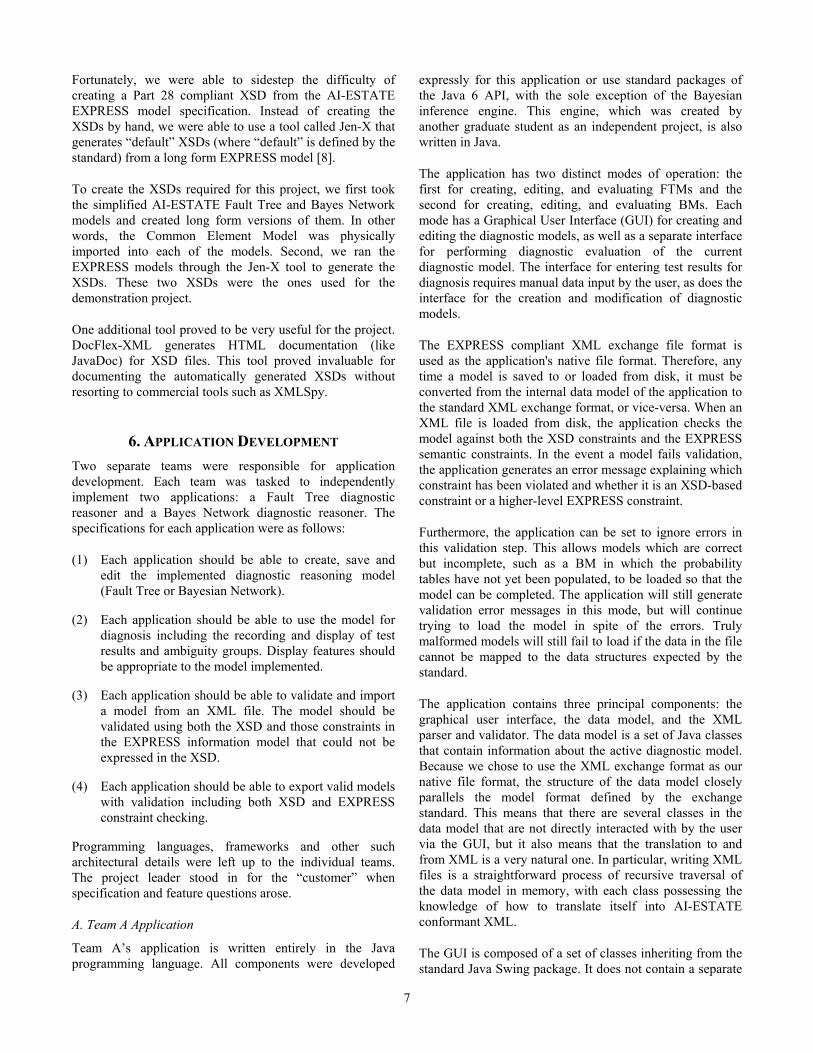
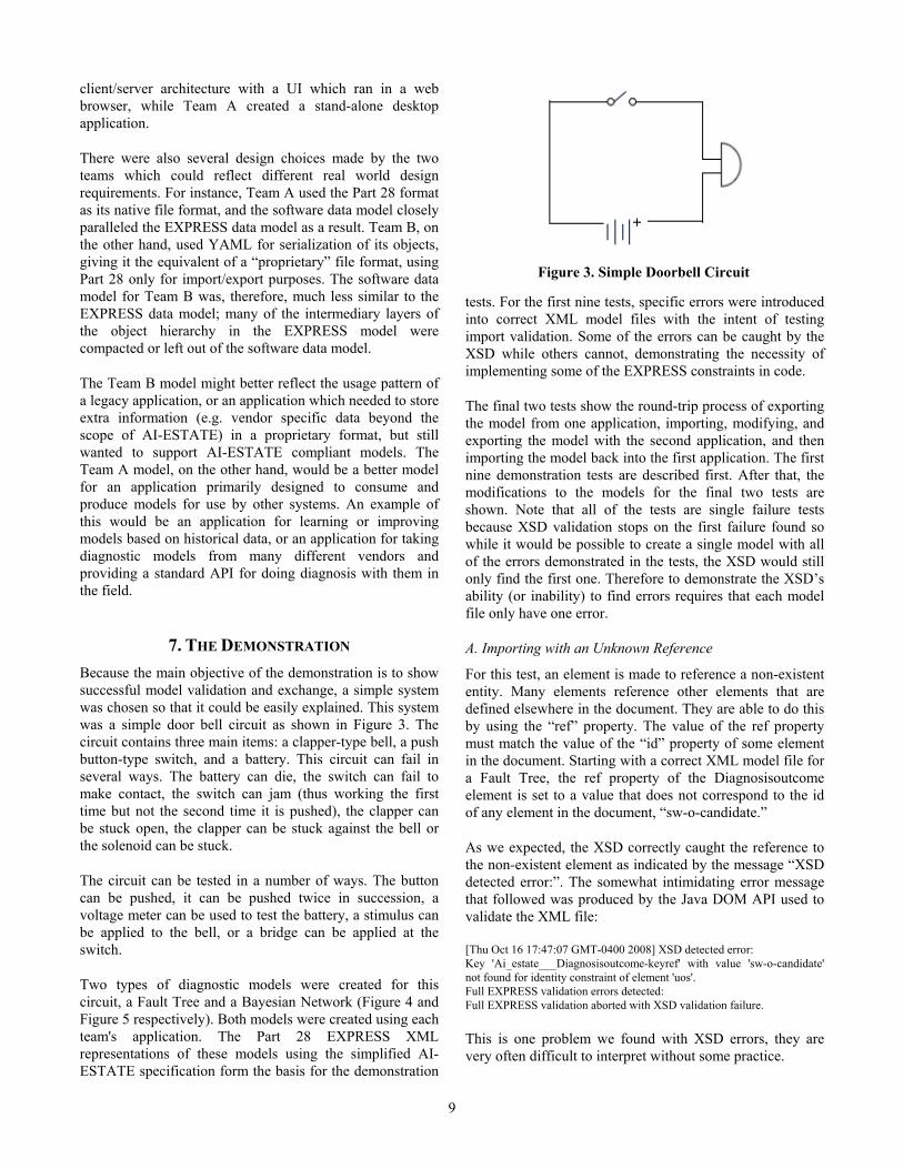
7. THE DEMONSTRATION Because the main objective of the demonstration is to show successful model validation and exchange, a simple system was chosen so that it could be easily explained. This system was a simple door bell circuit as shown in Figure 3. The circuit contains three main items: a clapper-type bell, a push button-type switch, and a battery. This circuit can fail in several ways. The battery can die, the switch can fail to make contact, the switch can jam (thus working the first time but not the second time it is pushed), the clapper can be stuck open, the clapper can be stuck against the bell or the solenoid can be stuck.
The circuit can be tested in a number of ways. The button can be pushed, it can be pushed twice in succession, a voltage meter can be used to test the battery, a stimulus can be applied to the bell, or a bridge can be applied at the switch.
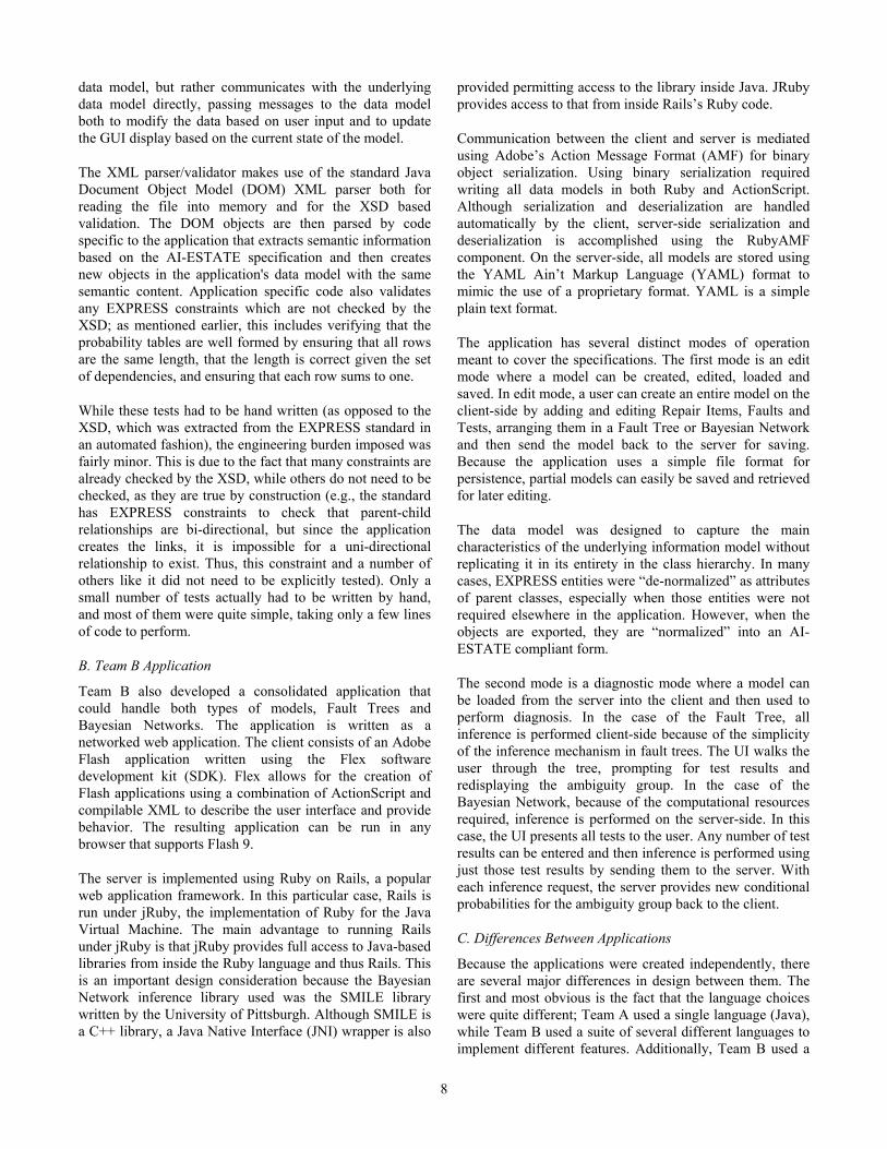
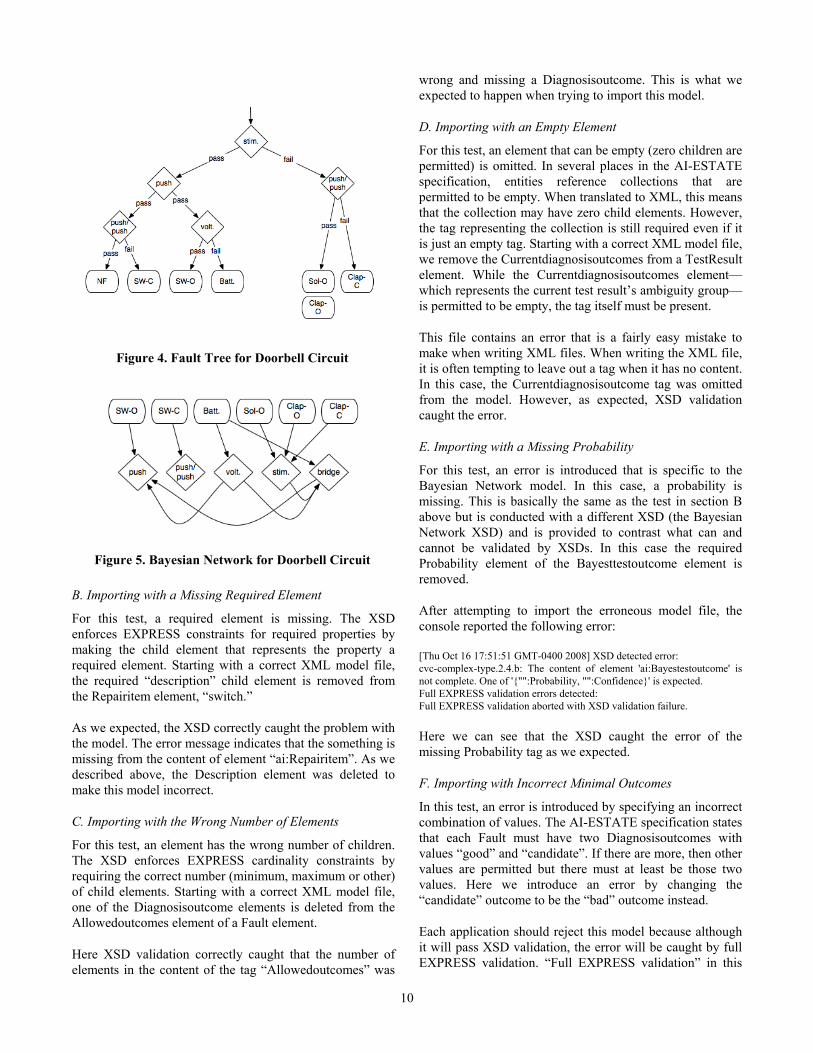
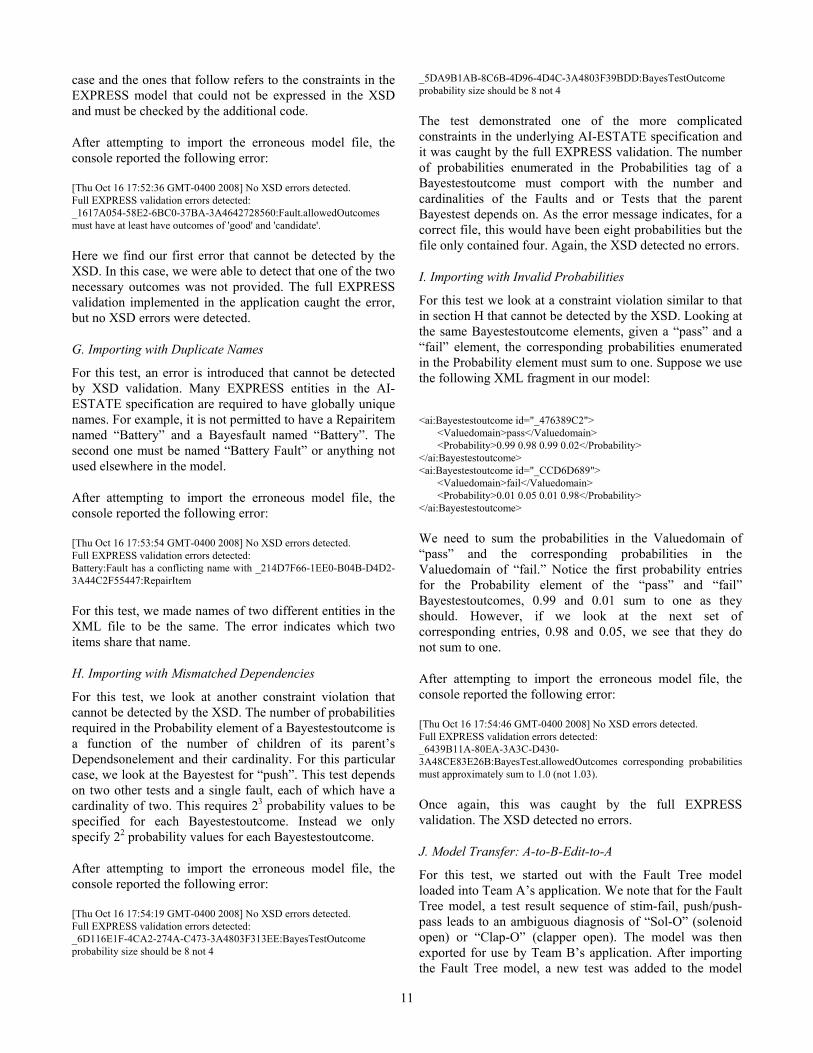
Two types of diagnostic models were created for this circuit, a Fault Tree and a Bayesian Network (Figure 4 and Figure 5 respectively). Both models were created using each team's application. The Part 28 EXPRESS XML representations of these models using the simplified AI-ESTATE specification form the basis for the demonstration
tests. For the first nine tests, specific errors were introduced into correct XML model files with the intent of testing import validation. Some of the errors can be caught by the XSD while others cannot, demonstrating the necessity of implementing some of the EXPRESS constraints in code.
The final two tests show the round-trip process of exporting the model from one application, importing, modifying, and exporting the model with the second application, and then importing the model back into the first application. The first nine demonstration tests are described first. After that, the modifications to the models for the final two tests are shown. Note that all of the tests are single failure tests because XSD validation stops on the first failure found so while it would be possible to create a single model with all of the errors demonstrated in the tests, the XSD would still only find the first one. Therefore to demonstrate the XSD’s ability (or inability) to find errors requires that each model file only have one error.
A. Importing with an Unknown Reference
For this test, an element is made to reference a non-existent entity. Many elements reference other elements that are defined elsewhere in the document. They are able to do this by using the “ref” property. The value of the ref property must match the value of the “id” property of some element in the document. Starting with a correct XML model file for a Fault Tree, the ref property of the Diagnosisoutcome element is set to a value that does not correspond to the id of any element in the document, “sw-o-candidate.”
As we expected, the XSD correctly caught the reference to the non-existent element as indicated by the message “XSD detected error:”. The somewhat intimidating error message that followed was produced by the Java DOM API used to validate the XML file:
[Thu Oct 16 17:47:07 GMT-0400 2008] XSD detected error: Key 'Ai_estate___Diagnosisoutcome-keyref' with value 'sw-o-candidate' not found for identity constraint of element 'uos'. Full EXPRESS validation errors detected: Full EXPRESS validation aborted with XSD validation failure.
This is one problem we found with XSD errors, they are very often difficult to interpret without some practice.
Figure 3. Simple Doorbell Circuit
10
B. Importing with a Missing Required Element
For this test, a required element is missing. The XSD enforces EXPRESS constraints for required properties by making the child element that represents the property a required element. Starting with a correct XML model file, the required “description” child element is removed from the Repairitem element, “switch.”
As we expected, the XSD correctly caught the problem with the model. The error message indicates that the something is missing from the content of element “ai:Repairitem”. As we described above, the Description element was deleted to make this model incorrect.
C. Importing with the Wrong Number of Elements
For this test, an element has the wrong number of children. The XSD enforces EXPRESS cardinality constraints by requiring the correct number (minimum, maximum or other) of child elements. Starting with a correct XML model file, one of the Diagnosisoutcome elements is deleted from the Allowedoutcomes element of a Fault element.
Here XSD validation correctly caught that the number of elements in the content of the tag “Allowedoutcomes” was
wrong and missing a Diagnosisoutcome. This is what we expected to happen when trying to import this model.
D. Importing with an Empty Element
For this test, an element that can be empty (zero children are permitted) is omitted. In several places in the AI-ESTATE specification, entities reference collections that are permitted to be empty. When translated to XML, this means that the collection may have zero child elements. However, the tag representing the collection is still required even if it is just an empty tag. Starting with a correct XML model file, we remove the Currentdiagnosisoutcomes from a TestResult element. While the Currentdiagnosisoutcomes element—which represents the current test result’s ambiguity group—is permitted to be empty, the tag itself must be present.
This file contains an error that is a fairly easy mistake to make when writing XML files. When writing the XML file, it is often tempting to leave out a tag when it has no content. In this case, the Currentdiagnosisoutcome tag was omitted from the model. However, as expected, XSD validation caught the error.
E. Importing with a Missing Probability
For this test, an error is introduced that is specific to the Bayesian Network model. In this case, a probability is missing. This is basically the same as the test in section B above but is conducted with a different XSD (the Bayesian Network XSD) and is provided to contrast what can and cannot be validated by XSDs. In this case the required Probability element of the Bayesttestoutcome element is removed.
After attempting to import the erroneous model file, the console reported the following error:
[Thu Oct 16 17:51:51 GMT-0400 2008] XSD detected error: cvc-complex-type.2.4.b: The content of element 'ai:Bayestestoutcome' is not complete. One of '{"":Probability, "":Confidence}' is expected. Full EXPRESS validation errors detected: Full EXPRESS validation aborted with XSD validation failure.
Here we can see that the XSD caught the error of the missing Probability tag as we expected.
F. Importing with Incorrect Minimal Outcomes
In this test, an error is introduced by specifying an incorrect combination of values. The AI-ESTATE specification states that each Fault must have two Diagnosisoutcomes with values “good” and “candidate”. If there are more, then other values are permitted but there must at least be those two values. Here we introduce an error by changing the “candidate” outcome to be the “bad” outcome instead.
Each application should reject this model because although it will pass XSD validation, the error will be caught by full EXPRESS validation. “Full EXPRESS validation” in this
Figure 4. Fault Tree for Doorbell Circuit
Figure 5. Bayesian Network for Doorbell Circuit
11
case and the ones that follow refers to the constraints in the EXPRESS model that could not be expressed in the XSD and must be checked by the additional code.
After attempting to import the erroneous model file, the console reported the following error:
[Thu Oct 16 17:52:36 GMT-0400 2008] No XSD errors detected. Full EXPRESS validation errors detected: _1617A054-58E2-6BC0-37BA-3A4642728560:Fault.allowedOutcomes must have at least have outcomes of 'good' and 'candidate'.
Here we find our first error that cannot be detected by the XSD. In this case, we were able to detect that one of the two necessary outcomes was not provided. The full EXPRESS validation implemented in the application caught the error, but no XSD errors were detected.
G. Importing with Duplicate Names
For this test, an error is introduced that cannot be detected by XSD validation. Many EXPRESS entities in the AI-ESTATE specification are required to have globally unique names. For example, it is not permitted to have a Repairitem named “Battery” and a Bayesfault named “Battery”. The second one must be named “Battery Fault” or anything not used elsewhere in the model.
After attempting to import the erroneous model file, the console reported the following error:
[Thu Oct 16 17:53:54 GMT-0400 2008] No XSD errors detected. Full EXPRESS validation errors detected: Battery:Fault has a conflicting name with _214D7F66-1EE0-B04B-D4D2-3A44C2F55447:RepairItem
For this test, we made names of two different entities in the XML file to be the same. The error indicates which two items share that name.
H. Importing with Mismatched Dependencies
For this test, we look at another constraint violation that cannot be detected by the XSD. The number of probabilities required in the Probability element of a Bayestestoutcome is a function of the number of children of its parent’s Dependsonelement and their cardinality. For this particular case, we look at the Bayestest for “push”. This test depends on two other tests and a single fault, each of which have a cardinality of two. This requires 23 probability values to be specified for each Bayestestoutcome. Instead we only specify 22 probability values for each Bayestestoutcome.
After attempting to import the erroneous model file, the console reported the following error:
[Thu Oct 16 17:54:19 GMT-0400 2008] No XSD errors detected. Full EXPRESS validation errors detected: _6D116E1F-4CA2-274A-C473-3A4803F313EE:BayesTestOutcome probability size should be 8 not 4
_5DA9B1AB-8C6B-4D96-4D4C-3A4803F39BDD:BayesTestOutcome probability size should be 8 not 4
The test demonstrated one of the more complicated constraints in the underlying AI-ESTATE specification and it was caught by the full EXPRESS validation. The number of probabilities enumerated in the Probabilities tag of a Bayestestoutcome must comport with the number and cardinalities of the Faults and or Tests that the parent Bayestest depends on. As the error message indicates, for a correct file, this would have been eight probabilities but the file only contained four. Again, the XSD detected no errors.
I. Importing with Invalid Probabilities
For this test we look at a constraint violation similar to that in section H that cannot be detected by the XSD. Looking at the same Bayestestoutcome elements, given a “pass” and a “fail” element, the corresponding probabilities enumerated in the Probability element must sum to one. Suppose we use the following XML fragment in our model:
<ai:Bayestestoutcome id="_476389C2"> <Valuedomain>pass</Valuedomain> <Probability>0.99 0.98 0.99 0.02</Probability> </ai:Bayestestoutcome> <ai:Bayestestoutcome id="_CCD6D689"> <Valuedomain>fail</Valuedomain> <Probability>0.01 0.05 0.01 0.98</Probability> </ai:Bayestestoutcome>
We need to sum the probabilities in the Valuedomain of “pass” and the corresponding probabilities in the Valuedomain of “fail.” Notice the first probability entries for the Probability element of the “pass” and “fail” Bayestestoutcomes, 0.99 and 0.01 sum to one as they should. However, if we look at the next set of corresponding entries, 0.98 and 0.05, we see that they do not sum to one.
After attempting to import the erroneous model file, the console reported the following error:
[Thu Oct 16 17:54:46 GMT-0400 2008] No XSD errors detected. Full EXPRESS validation errors detected: _6439B11A-80EA-3A3C-D430-3A48CE83E26B:BayesTest.allowedOutcomes corresponding probabilities must approximately sum to 1.0 (not 1.03).
Once again, this was caught by the full EXPRESS validation. The XSD detected no errors.
J. Model Transfer: A-to-B-Edit-to-A
For this test, we started out with the Fault Tree model loaded into Team A’s application. We note that for the Fault Tree model, a test result sequence of stim-fail, push/push-pass leads to an ambiguous diagnosis of “Sol-O” (solenoid open) or “Clap-O” (clapper open). The model was then exported for use by Team B’s application. After importing the Fault Tree model, a new test was added to the model
12
“Open” (for “open” bell casing). By visual inspection of the opened bell, this test can resolve the previously noted ambiguity. After creating the test, it was added to the proper place in the Fault Tree. The model was then exported and then imported back into Team A’s application where the changes were visible. The process completed successfully as expected.
K. Model Transfer: B-to-A-Edit-to-B
For this test, we started out with the Bayes Network and Team B’s application. We first exported the model and loaded it into Team A’s application. For this test we noted that the battery, bell and switch are not the only components of the bell circuit. There is also the wiring. For this modification, we added a new Repairitem (wiring), a new Fault (wiring fault) and a new Test (short). For simplicity, we made the Test depend directly on only the wiring fault. After editing the model, we exported it and then re-imported it into Team B’s application where the changes were visible. The process completed successfully as expected.
8. CONCLUSIONS Two of the primary motivations behind the DoD adopting consensus standards for ATS development are to reduce cost by improving interoperability and to minimize repeated design of similar systems. The IEEE SCC20 standards focus on promoting information interoperability between components of a test or health monitoring system. The emphasis by the DOD on acquisition reform based on commercial standards for ATS, combined with declining budgets mandates the need for more affordable health management system development and operation.
A key objective of the demonstration reported here was to show that information can be shared between applications in such a way that re-engineering is minimized, external agreements on handling the data are minimized and, if possible, eliminated, and information validation is provided beyond simple structural validation. An associated concern is whether the implementation of standards purporting to provide these characteristics can be done in a cost-effective manner. It is clear from this demonstration that AI-ESTATE satisfies all of these concerns when exchanging diagnostic models. A pair of complete fault tree and Bayesian diagnostic systems was developed, including facilities to export, import, and semantically validate diagnostic models. Furthermore, these systems were developed from scratch by three graduate students working part time for four months.
ACKNOWLEDGMENTS We thank Heidi Preston for permitting us to use the Jen-X tool and for her assistance in resolving some issues, both with the tool and with our models. We also thank the Decision Systems Laboratory at the University of Pittsburgh
for allowing us to use their SMILE reasoning engine in one of the Bayesian applications. We thank Charles Robertson for allowing us to use his BayesNetBuilder engine for the other Bayesian application. Finally, we thank Michael Malesich, Jennifer Fetherman, Michael Seavey Mukund Modi, Joseph Stanco, Timothy Wilmering, Michelle Harris, Darryl Busch, and the anonymous reviewers for their guidance, both in the completion of this project and in the preparation of this paper. This work was supported via the Johns Hopkins University Applied Physics Laboratory under contract N00024-03-D-6606 with the US Navy.
REFERENCES [1] IEEE Std 1232-2002, IEEE Standard for Artificial
Intelligence Exchange and Service Tie to All Test Environments (AI-ESTATE), Piscataway, New Jersey: IEEE Standards Association Press, 2002.
[2] IEEE P1232, Draft IEEE Standard for Artificial Intelligence Exchange and Service Tie to All Test Environments (AI-ESTATE), D1.0, Piscataway, New Jersey: IEEE Standards Association Press, 2008.
[3] ISO 10303-11:1994, Industrial Automation Systems and Integration—Product Data Representation and Exchange—Part 11: Description Methods: The EXPRESS Language Reference Manual, Geneva, Switzerland: International Organization for Standardization, 1994.
[4] ISO 10303-28:2007, Industrial Automation Systems and Integration—Product Data Representation and Exchange—Part 28: XML Representation of EXPRESS Schemas and Data using XML Schemas, Geneva, Switzerland: International Organization for Standardization, 2007.
[5] ISO 10303-21:1994, Industrial Automation Systems and Integration—Product Data Representation and Exchange—Part 21: Implementation Methods: Clear Text Encoding of the Exchange Structure, Geneva, Switzerland: International Organization for Standardization, 1994.
[6] Busch, D., “Validation of XML Data Against an EXPRESS Schema Using XSLT Translation to Part 21 Format,” IEEE AUTOTESTCON 2007 Conference Record, IEEE Press, pp. 64–71, September 2007.
[7] W3C, Web Services Description Language (WSDL), v1.1, W3C Note, http://www.w3.org/TR/wsdl, March 15, 2001.
[8] Preston H., T. Rondo, and J. Tennison, The Jen-X Tool for EXPRESS-to-Part 28 Conversion, v. 2.0, available from http://pdesinc.aticorp.org/vendor/Jen-X.html.
13
BIOGRAPHIES
John Sheppard is the RightNow Technologies Distinguished Professor of Computer Science at Montana State University. He is also an Associate Research Professor at Johns Hopkins University. His research interests include algorithms for diagnostic and prognostic reasoning, machine learning and data mining in temporal systems, and reinforcement learning.
Dr. Sheppard holds a BS in computer science from Southern Methodist University and an MS and PhD in computer science from Johns Hopkins University. He is a fellow of the IEEE and currently serves as Vice Chair of the IEEE Standards Coordinating Committee 20 (SCC20) on Test and Diagnosis for Electronic Systems
Steve Butcher is currently pursuing his PhD in computer science at the Johns Hopkins University. He has served as a lecturer in economics and grader in computer science. He received his BA in economics from the California State University, Sacramento, his MA in economics from The American University, Washington, DC, and his MS in
computer science from Johns Hopkins. His research interests are in machine learning and include Bayesian networks and evolutionary computation.
Patrick Donnelly is currently pursuing his Ph.D in computer science at Johns Hopkins University. He previously received a BS in computer science and an AB in music history and Italian literature from Washington University in St. Louis. He also holds an MSE in computer science from the Whiting School at Johns Hopkins, and both the MM in musicology and the MM in
computer music from the Peabody Conservatory at Johns Hopkins. His research interests are primarily in machine learning in the musical domain.
Benjamin Mitchell is currently pursuing a PhD in the Johns Hopkins University department of computer science. He has previously received a BA in computer science from Swarthmore College, and an MSE in computer science from Johns Hopkins University. His interests are in artificial intelligence and machine learning, with an emphasis on finding
solutions to the problems involved in autonomous mobile robotics.