demonstration of a wide dynamic range angular rate sensor...
TRANSCRIPT

Demonstration of a Wide Dynamic Range Angular Rate Sensor Based on Frequency Modulation
Sergei A. Zotov, Alexander A. Trusov, Andrei M. Shkel
MicroSystems Laboratory, Mechanical and Aerospace Engineering University of California, Irvine, CA, USA
[email protected], [email protected], [email protected]
Abstract— This paper reports a detailed characterization of a new rate gyroscope based on the mechanical frequency modulation (FM) of the input rotation. The FM approach tracks the resonant frequency split between two high-Q mechanical modes of vibration in a MEMS Coriolis Vibratory Gyroscope (CVG) to produce a frequency-based measurement of the input angular rate. The FM approach was implemented using a silicon micromachined Quadruple Mass Gyroscope (QMG) transducer. Structural characterization of a vacuum packaged QMG showed symmetrical Q-factors on the order of 1 million over a wide temperature range from -40 ˚C to +100 ˚C. High speed rate table testing of the FM angular rate sensor demonstrated inherent linearity up to 18,000 deg/s (50 revolutions per second, limited by the setup) with a dynamic range exceeding 125 dB. Interchangeable operation of the QMG transducer in conventional AM and proposed FM regimes provides a dynamic range above 155 dB (from sub-deg/hr to 18,000 deg/s).
I. INTRODUCTION
Conventional vibratory rate gyroscopes are operated as analog Amplitude Modulation (AM) systems, where the mechanical sense-mode sinusoidal response is excited by the input angular rate amplitude-modulated by the drive-mode velocity due to the Coriolis effect. Mode matching of conventional high-Q angular rate gyroscopes increases the signal-to-noise-ratio at the tradeoff of open loop linear range and bandwidth [1]. These constraints stem from a fundamental Q-versus-bandwidth tradeoff and dynamic range limitations of analog AM systems. The AM-based angular rate operation of mode-matched vibratory gyroscopes is also very sensitive to the value of the sense-mode Q-factor, resulting in significant scale factor drifts over practical variations in the operational temperature and pressure. To address these challenges, a novel operating principle for a rate sensor which relies on tracking of the resonant frequencies of two high-Q mechanical modes of vibration to produce a quasi-digital FM measurement of the input angular rate was recently introduced in [2]. This rate sensor architecture is enabled by a combination of a symmetric, high Q, silicon micromachined Quadruple Mass Gyroscope (QMG) [3] and a new FM-based principle of operation and instrumentation [4], which takes advantage of a previously ignored mechanical FM effect in vibratory rate gyroscope dynamics, Fig. 1. This paper provides a more detailed experimental characterization of the FM gyroscope, including demonstration of wide linear and dynamic ranges.
II. FREQUENCY BASED DETECTION OF ANGULAR RATE
Fig. 1 shows a schematic of a z-axis vibratory gyroscope considered as a proof mass m suspended in the x-y plane of vibration. Assuming negligible damping, the free vibrations of a mode matched device in the moving device frame Oxy are:
( )( ) ,02
,0222
22
=Ω+Ω−++Ω
=Ω−Ω−++Ω−
xyyx
yxxy
zzz
zzz
ωω (1)
where ω is the mechanical natural frequency for Ωz=0 input.
The device reference frame Oxy is rotating relative to an inertial frame Oξη with Ωz rate. In the inertial frame Oξη, the gyro dynamics decouples into two separate equations:
.0,0 22 =+=+ ηωηξωξ (2)
The solution to (2) is ξ(t)=Asin(ωt) and η(t)=Bsin(ωt+φ). By choosing the inertial frame and initial conditions properly, the gyroscope vibrations are along a fixed line in inertial space:
ξ(t)=Asin(ωt), η(t)=0. (3) The free vibration pattern (3) can be now mapped back to the rotating reference frame Oxy attached to the gyroscope:
x(t)=Asin(ωt)cos(Ωzt), y(t)=Asin(ωt)sin(Ωzt). (4)
This work was supported by the ONR/NSWCDD under Grants N00014-09-1-0424 and N00014-11-1-0483.
Figure 1. Concept of the FM-based rate sensor. Rotation causes a split between the two initially matched modes, producing an FM rate output.
x
y
x
y
PLL
PLL
Gyro Output
FM (Digital) z
z
Y-mode, FFT
X-mode, FFT
z
m
(measured)
(measured)
978-1-4244-9288-6/11/$26.00 ©2011 IEEE 149

Using trigonometric identities and assuming a quasi-static input angular rate Ωz, (4) is equivalent to
( )( ),)cos()cos(5.0
,)sin()sin(5.0
21
21
ttAy
ttAx
λλλλ
+−=+= (5)
where
,, 21 zz Ω−=Ω+= ωλωλ (6) are the effective modal frequencies with respect to the rotating reference frame Oxy in presence of Ωz≠0 input. Gyroscope’s vibrations contain only one frequency ω with respect to the inertial frame (3). At the same time, two splitting frequencies λ1,2=ω±Ωz are observed (5) with respect to the device moving frame Oxy, Fig. 2. The frequency modulation effect (4) is inherent to the moving reference frame and enables measuring the input rate Ωz from the observed split in modal frequencies λ1,2 according to
( ).5.0 21 λλ −=Ω z
The FM based approach is also valid for non-ideal gyroscopes with initial mismatch between two modes [2].
III. SYMMETRIC HIGH-Q TRANSDUCER DESIGN
Several design criteria must be met by the mechanical sensor element to fully realize the advantages of the proposed FM operation. A geometrically symmetric and mode-matched structure is needed to optimize the minimal detectable rate signal and increase the temperature stability of the sensor. At the same time, identical high Q is needed in both modes of mechanical vibration to maximize the modal frequency stability and rate resolution. These requirements are satisfied by an x-y symmetric, dynamically balanced, anti-phase operated gyroscope, such as the recently introduced Quadruple mass Gyroscope (QMG) architecture [3,5].
The mechanical structure of the QMG mechanical sensor element comprises four identical, symmetrically decoupled tines with linear coupling flexures as well as a pair of anti-
phase synchronization lever mechanisms for both in-plane modes of balanced anti-phase vibration, Fig. 3. This x-y symmetric system of four anti-phase tines provides the structure with two anti-phase, dynamically balanced modes of mechanical vibration at a single operational frequency. The complete x-y structural symmetry of the device improves robustness of frequency matching against the fabrication imperfections and temperature induced frequency drifts.
IV. EXPERIMENTAL CHARACTERIZATION
This section describes experimental evaluation of a vacuum sealed QMG instrumented for FM rate measurement.
A. Prototype Fabrication and Packaging
The QMG sensor element used for the experimental characterization was fabricated using an in-house, single mask, wafer scale SOI process with a conductive 100 μm thick device layer and a 5 μm thick buried oxide. First, a hard mask for sensor structures was defined by patterning a thermally grown 1 μm layer of surface oxide with a Surface Technology Systems (STS) Advanced Oxide Etching (ASE) tool. The gyroscope structures were then defined by DRIE using a Unaxis Versaline VL-7339 tool. The singulated sensors were released using a timed 20 % hydrofluoric acid wet etch. The released QMG devices were bonded to ceramic DIP packages using Au-Sn eutectic solder and wire bonded. To enable stand-alone high Q operation, the packaged sensors were vacuum sealed using custom made glass lids with getter material providing robust sub-mTorr vacuum inside the package cavity [6], Fig. 4.
B. Structural Characterization
The structural x- and y-modes of a vacuum sealed QMG prototype were experimentally characterized at different temperatures using ring-down tests in a Test Equity 107 thermal chamber. Exponential fits of the time domain amplitude decay data showed time constants τx=167 s and τy=169 seconds for the two modes, respectively, confirming
(a) x-mode displacement. (b) y-mode displacement.
Figure 3. Finite element modeling of QMG showing two balanced, low dissipation modes of anti-phase vibration at the same frequency.
Figure 4. Photograph of an SOI prototype of QMG sensor vacuum packaged at sub-mTorr cavity pressure using a custom lid with getters.
Figure 2. Free vibrations of an ideal mode-matched gyroscope with respect to the rotating frame of reference Oxy show two frequencies: the gyroscope’s natural frequency ω and the input rotation frequency Ωz.
x
y
t
t
=0
Envelope at freqz . Gyro oscillation at freq.
X-mode
Y-mode
150

structural and damping symmetry, Fig. 5. The Q-factors were calculated from the measured decay constants τ according to Q=πfnτ, where the measured natural frequency is fn 2.2 kHz for both modes. The measured Q-factors of above 1.1 million agree well with the fundamental thermoelastic limit computed using FEM software COMSOL. Characterization of Q-factors over a -40 ˚C to +100 ˚C temperature range is shown in Fig. 6. For T> 0 ˚C, the data exhibits 1/T3 dependency, which is characteristic for thermoelastic dissipation [7]. Below 0 ˚C the device Q-factor levels off at approximately 1.7 million, attributed to anchor loss due to slight structural imbalances.
C. Interface Electronic and Signal Processing
For rate table characterization a vacuum packaged QMG was mounted to a PCB containing signal detection electronics. Front-end amplification of the output signals was done using two transimpedance and a differential instrumentation amplifier for both x- and y-modes. Signal processing and demodulation was implemented in real-time using a programmable Zurich Instruments HF2 lock-in amplifier. Separation of the useful signal from the feedthrough signal was accomplished using electromechanical amplitude modulation (EAM), where a carrier voltage of 0.5 V at 52 kHz is applied to the proof mass. The signals from both the x- and y-modes containing FM modulated angular rate information were fed into two separate Phase Lock Loops (PLLs). The two PPLs tracked the natural frequencies of the respective vibratory modes in order to produce the angular rate output and provide closed-loop excitation to the gyroscope, Fig. 7.
D. Demonstration of Mechanical Frequency Modulaion
In order to experimentally demonstrate the effect of mechanical frequency modulation in a rotating gyroscope, a vacuum packaged QMG with a mismatch of approximately 0.1 Hz was tested on an Ideal Aerosmith 2102 rate table. Initially, the rate table was stationary and one of the gyroscope’s x-mode was excited into resonance by closing the gate, Fig. 7. The gate was then opened to allow free vibration, and an input angular rate was applied. Acquisition of the x- and y-modes of free vibration was done using a LeCroy WaveRunner 64Xi oscilloscope, while an FFT analysis was simultaneously conducted on an HP 35665A Dynamic Signal Analyzer. Measured time domain vibrations of the x- and y-modes in presence of a 100 deg/s angular rate input are shown in Fig. 8. Both signals contain sinusoidal components at a 2.2 kHz initial mechanical frequency as well as a lower frequency signal produced by the constant input rotation.
The experiment demonstrates the energy exchange between x- and y-modes and the frequency modulation of the input rotation rate described by the simple mathematical model (4). The pattern of vibrations remains fixed in inertial space, which can be used for the realization of a micromachined whole angle gyroscope [3, 8].
Figure 7. Schematic of signal processing for FM based angular rate sensor instrumentaiton, including detection and closed-loop excitation.
Figure 8. Measured output of x- and y-modes of a vacuum sealed QMG experimentally illustrates the rate dependent frequency split phenomenon.
Vacuum sealed gyroscopeVacuum sealed gyroscopeVacuum sealed gyroscope
X-mode
Demod PLL
Carrier
Carrier
X-mode
Switch
oscillation
First ( )1
modal freq.
Y-mode
Demod PLL
Y-modeoscillation
Second ( )2
modal freq.Carrier
Y-m
od
eX
-mo
de
1 2 3 4 5 6 7 8
Time, s
zzz
Time, s1 2 3 4 5 6 7 8
1 2 3 4 5 6 7 81 2 3 4 5 6 7 8
Envelope at freqz .
Gyro oscillation at freq.
Figure 5. Experimental characterization of the packaged QMG using ring-down test, showing identical Q-factor for both x- and y-modes.
Figure 6. Q-factor vs. temperature for packaged QMG, showing 1/T3 dependence characteristic of thermoelastic dissipation (for T > 0 °C).
1
0.9
0.8
0.7
0.6
0.5
0.4 1/e
0 40 80 120 160 200Time, s
Norm
aliz
edam
pli
tudes
of
vib
rati
on
Measured decay:X-mode
Y-mode
0.375
0.36
0.365
0.371/e
167 168 169 170
y=169 s
x=167 s
1.8
1.6
1.4
1.2
1.0
0.8
-40 -20 0 20 40 60 80 1000.6
Q-f
acto
r,M
illi
on
Temperature, C
Measured data
Q1/T3
Anchor loss limit
QTED
151
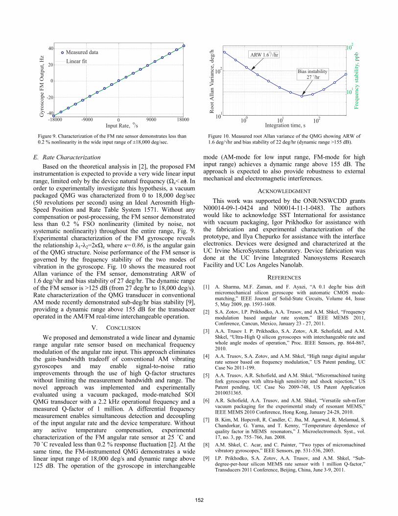
Figure 10. Measured root Allan variance of the QMG showing ARW of 1.6 deg/√hr and bias stability of 22 deg/hr (dynamic range >155 dB).
10
101
2
RootA
llan
Vari
ance,deg/h
10 10100 1 2
Integration time, s
Fre
quency
stabil
ity,ppb
101
Bias instability27 /hr
ARW 1.6 / hr
102
Figure 9. Characterization of the FM rate sensor demonstrates less than 0.2 % nonlinearity in the wide input range of ±18,000 deg/sec.
Gy
rosc
op
eF
MO
utp
ut,
Hz
0
20
40
9000
Input Rate, /s
Measured data
Linear fit
0
18000-9000-18000
-20
-40
E. Rate Characterization
Based on the theoretical analysis in [2], the proposed FM instrumentation is expected to provide a very wide linear input range, limited only by the device natural frequency (Ωz<ω). In order to experimentally investigate this hypothesis, a vacuum packaged QMG was characterized from 0 to 18,000 deg/sec (50 revolutions per second) using an Ideal Aerosmith High-Speed Position and Rate Table System 1571. Without any compensation or post-processing, the FM sensor demonstrated less than 0.2 % FSO nonlinearity (limited by noise, not systematic nonlinearity) throughout the entire range, Fig. 9. Experimental characterization of the FM gyroscope reveals the relationship λ1-λ2=2κΩz where κ=0.86, is the angular gain of the QMG structure. Noise performance of the FM sensor is governed by the frequency stability of the two modes of vibration in the gyroscope. Fig. 10 shows the measured root Allan variance of the FM sensor, demonstrating ARW of 1.6 deg/√hr and bias stability of 27 deg/hr. The dynamic range of the FM sensor is >125 dB (from 27 deg/hr to 18,000 deg/s). Rate characterization of the QMG transducer in conventional AM mode recently demonstrated sub-deg/hr bias stability [9], providing a dynamic range above 155 dB for the transducer operated in the AM/FM real-time interchangeable operation.
V. CONCLUSION
We proposed and demonstrated a wide linear and dynamic range angular rate sensor based on mechanical frequency modulation of the angular rate input. This approach eliminates the gain-bandwidth tradeoff of conventional AM vibrating gyroscopes and may enable signal-to-noise ratio improvements through the use of high Q-factor structures without limiting the measurement bandwidth and range. The novel approach was implemented and experimentally evaluated using a vacuum packaged, mode-matched SOI QMG transducer with a 2.2 kHz operational frequency and a measured Q-factor of 1 million. A differential frequency measurement enables simultaneous detection and decoupling of the input angular rate and the device temperature. Without any active temperature compensation, experimental characterization of the FM angular rate sensor at 25 ˚C and 70 ˚C revealed less than 0.2 % response fluctuation [2]. At the same time, the FM-instrumented QMG demonstrates a wide linear input range of 18,000 deg/s and dynamic range above 125 dB. The operation of the gyroscope in interchangeable
mode (AM-mode for low input range, FM-mode for high input range) achieves a dynamic range above 155 dB. The approach is expected to also provide robustness to external mechanical and electromagnetic interferences.
ACKNOWLEDGMENT
This work was supported by the ONR/NSWCDD grants N00014-09-1-0424 and N00014-11-1-0483. The authors would like to acknowledge SST International for assistance with vacuum packaging, Igor Prikhodko for assistance with the fabrication and experimental characterization of the prototype, and Ilya Chepurko for assistance with the interface electronics. Devices were designed and characterized at the UC Irvine MicroSystems Laboratory. Device fabrication was done at the UC Irvine Integrated Nanosystems Research Facility and UC Los Angeles Nanolab.
REFERENCES [1] A. Sharma, M.F. Zaman, and F. Ayazi, “A 0.1 deg/hr bias drift
micromechanical silicon gyroscope with automatic CMOS mode-matching,” IEEE Journal of Solid-State Circuits, Volume 44, Issue 5, May 2009, pp. 1593-1608.
[2] S.A. Zotov, I.P. Prikhodko, A.A. Trusov, and A.M. Shkel, “Frequency modulation based angular rate system,” IEEE MEMS 2011, Conference, Cancun, Mexico, January 23 - 27, 2011.
[3] A.A. Trusov I. P. Prikhodko, S.A. Zotov, A.R. Schofield, and A.M. Shkel, “Ultra-High Q silicon gyroscopes with interchangeable rate and whole angle modes of operation,” Proc. IEEE Sensors, pp. 864-867, 2010.
[4] A.A. Trusov, S.A. Zotov, and A.M. Shkel, “High range digital angular rate sensor based on frequency modulation,” US Patent pending, UC Case No 2011-199.
[5] A.A. Trusov, A.R. Schofield, and A.M. Shkel, “Micromachined tuning fork gyroscopes with ultra-high sensitivity and shock rejection,” US Patent pending, UC Case No 2009-748, US Patent Application 2010031365.
[6] A.R. Schofield, A.A. Trusov, and A.M. Shkel, “Versatile sub-mTorr vacuum packaging for the experimental study of resonant MEMS,” IEEE MEMS 2010 Conference, Hong Kong, January 24-28, 2010.
[7] B. Kim, M. Hopcroft, R. Candler, C. Jha, M. Agarwal, R. Melamud, S. Chandorkar, G. Yama, and T. Kenny, “Temperature dependence of quality factor in MEMS resonators,” J. Microelectromech. Syst., vol. 17, no. 3, pp. 755–766, Jun. 2008.
[8] A.M. Shkel, C. Acar, and C. Painter, ”Two types of micromachined vibratory gyroscopes,” IEEE Sensors, pp. 531-536, 2005.
[9] I.P. Prikhodko, S.A. Zotov, A.A. Trusov, and A.M. Shkel, “Sub-degree-per-hour silicon MEMS rate sensor with 1 million Q-factor,” Transducers 2011 Conference, Beijing, China, June 3-9, 2011.
152