demonstration of possible flow conditions in a culvert
TRANSCRIPT

D emonstration of Possible F low Conditions in a Culvert M. R. CARSTENS, Associate Professor, Georgia Institute of Technology and A. R. HOLT, Lt. U.S. Army Corps of Engineers, Fort Belvoir, Virginia
e THE majo~ity of possible flow profiles within a highway culvert were produced in a two-dimensional laboratory channel. The flow profiles were photographed; classified by the position of the control section; and analyzed in detail. From this qualitative study, the effects of entrance streamlining, barrel length and roughness, and outlet submergence are readily visualized.
NOMENCLATURE
The following nomenclature is used:
depth of flow
uniform flow depth or normal depth,
critical depth
height of the rectangular culvert section,
adverse slope (Sa <0) ,
horizontal slope (S0= 0 with y~ m) ,
mild slope (S0 > 0 and y0 > Ye ),
steep slope (Sa> 0 and y0 <Ye ) ,
Critical slope (S '.> 0 and y = y ), and 0 0 c
bottom slope
APPARATUS
In order to obtain a photographic record of many of the flow profiles in a highway culvert , a two-dimensional model was constructed ,with sidewalls of clear plastic. With rear lighting through the transparent culvert barrel, the water surface was readily photographed. The culvert barrel was rectangular in cross-section, O. 167 foot wide by O. 300 foot high by 3. 00 feet long. The culvert slope and the discharge through the culvert were adjustable. Slide gates could be inserted either upstream downstream from the culvert barrel. A removable insert was used to alter the inlet from an unstreamlined inlet to a streamlined inlet. With this experimental arrangement, a large number of geometric and flow variations could be qualitatively observed.
SCOPE
The outlet conditions were varied from that of a free outlet to that of a completely submerged outlet. This control was by means of a downstream slide gate and a perpendicular drop in the channel bottom at the barrel outlet section.
The value of the critical depth y 6 in relation to the culvert height D is a primary
variable in the analysis of flow conditions through a highway culvert. The value of D
was fixed but the value of y was varied by discharge adjustment. In Figures 1 through 5, the black line parallel tocthe culvert is pla ced on the value of Ye·
The length, "roughness, and slope of the barrel are interdependent (except for short culverts in which the length-height ratio is less than about three) in the effect upon the form of the free surface profile: The validity of this statement is apparent by consider-
l
2
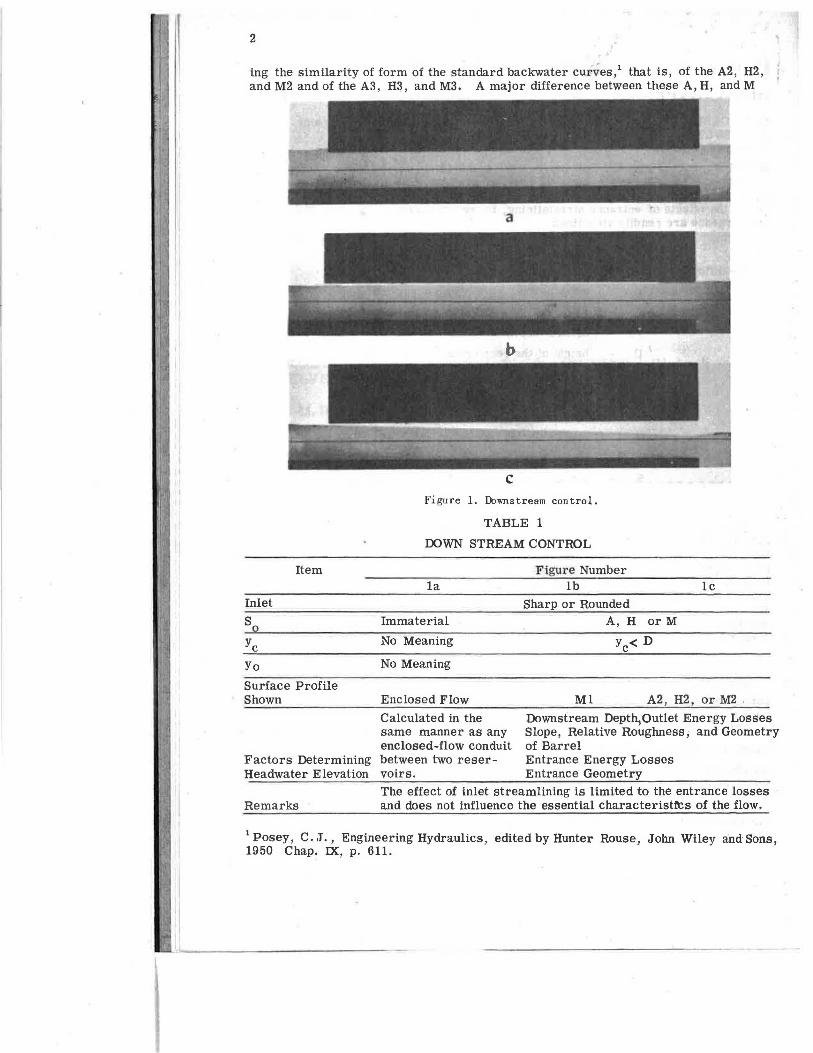
ing the similarity of form of the standard backwater cur,.;es,1 that is, of the A2, H2, and M2 and of the A3, H3, and M3. A major difference between these A, H, and M
Item
Inlet
Yo Surface Profile Shown
c Figure I. D:iwnstream control.
TABLE 1
DOWN STREAM CONTROL
la
Immaterial
No Meaning
No Meaning
Enclosed Flow
Calculated in the same manner as any enclosed-flow conduit
Figure Number lb
Sharp or Rounded A, H or M
Y<D c
le
Ml A2, H2, or M2 ,
Downstream Depth,Outlet Energy Losses Slope, Relative Roughness; and Geometry of Barrel
Factors Determining between two reserHeadwater Elevation voirs.
Entrance Energy Losses Entrance Geometry
Remarks The effect of inlet streamlining is limited to the entrance losses and does not influence the essential characteristfcs of the flow.
1 Posey, C. J., Engineering Hydraulics, edited by Hunter Rouse, John Wiley and Sons, 1950 Chap. IX, p. 611.

3
profiles is in the length of channel required to obtain a given depth change. The profiles on the adverse slope are much shorter than on a mild slope. Hence, for purposes of illustration, the depth changes have been exaggerated with adverse slopes in Figures
Item
Inlet So Ye y
Surface Profile Shown Factors Determining Headwater Elevation
Remarks
2a
TABLE 2
OUTLET CONTROL
Figure Number 2b and 2c
Sharp or Rounded A , H, or M y < D
Upstream portion enclosed; A2, H2, or M2 downstream portion -A2, H2, or M2 Elevation of Outlet Slope, Relative Roughness, and Geometry of.,the barrel Entrance Energy Losses Entrance Geometry
c
Figures 2b and 2c are identical except for the degree of inlet streamlining. The difference in the two flow conditions is restricted only to the energy losses at the inlet.
Figure 2. Outlet control.
le 2a, 2b, 2c, 4c, 4e, 4f, 5c, an·d 5d. There are no similar profiles to the Ml, Sl,

4
S2, and S3 profile which can be obtained by slope adjustment. However, the length of channel required to obtain a given depth change can be adjusted by roughness variation. As the channel roughness is increased, the length of the surface profile is decreased. In Figure 5d added roughness was used. Thus the geometric length of the culvert was fixed at a value of lOD but the effective length of the culvert was greater in the cases mentioned.
Only the extreme limits of the inlet geometry have been illustrated. The sides and bottom of the inlet were suppressed. One limit was obtained by the use of a sharp (right-angle) junction between the barrel roof and the headwall. With the sharp inlet, the contracted jet would be the same as the jet from under a sluice gate with a coefficient of contraction of approximately O. 6. Since this contraction occurs solely on the upper surface and since the surface waves are a minimum with supressed sides, this inlet condition represents an extreme limit of surface contraction. The limit of no jet contraction was obtained with a well-rounded junction between the barrel roof and the headwall. These two extremes of inlet geometry are shown in Figures 3 and 4.
The control would be upstream from the culvert only in case the flow were supercritical approaching the culvert. This condition was obtained by means of an adjustable sluice gate upstream from the inlet as shown in Figure 5."
Item
Inlet
So Ye
Yo Surface Profile Shown
Factors Determining Headwater Elevation
Remarks
TABLE 3
TUBE CONTROL
3a
Rounded s
Yo:!> D
Uniform Flow in Barrel
Slope, Relative Roughness, and Geometry of the barrel. Entrance Energy Loss. Entrance Geometry On a steep slope with a rounded inlet, the profile sequence with increas ing discharge is as follows: a
(a) Figure 4g; (b) Figure 3a; (c) an unsteady
flow pattern in which "slugs" of air are periodically transported;
(d) Figure 3b (when the headwater elevation is in excess of 1. 5D).
Figure Number 3b
Sharp or Rounded Immaterial
Yet!: D No Meaning but limit is Yo > D
Enclosed Flow
Calculated in the same manner as any enclosed-flow conduit discharging into the atmosphere
If the inlet is rounded and yo t?: D, barrel will flow full. However, if the inlet is sharp, the control may shift to inlet control (Figure 4).
astraub, Lorenz G., Anderson, Alvin G., and Bowers, Charles E., "Importance of Inlet Design on Culvert Capacity", St. Anthony Falls Hydraulic Laboratory Technical Paper, No. 13, Series B, 1953.
5
ANALYSIS
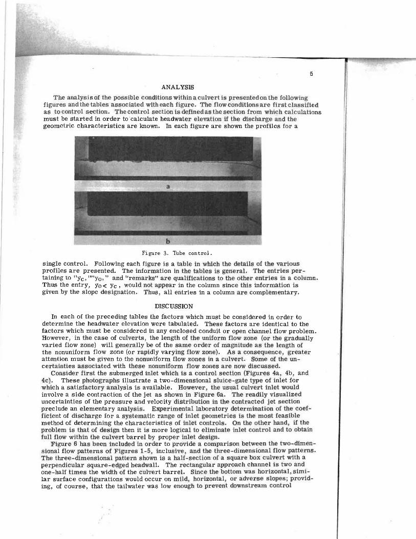
The analysis of the possible conditions within a culvert is presented on the following figures and the tables associated with each figure. The flow conditions are first classified as to control section. The control section is defined as the section from whic;h calculations must be started in order to 'calculate headwater elevation if the discharge and the geometric characteristics are known. In each figure are shown the profiles for a
Figure 3. Tube control.
single control. Following each figure is a table in which the details of the various profiles are presented. The information in the tables is general. The entries pertaining to "Ye, '"'y0 ," and "remarks" are qualifications to the other entries in a column. Thus the entry, Yo< Ye, would not appear in the column since this information is given by the slope designation. Thus, all entries in a column are complementary.
DISCUSSION
In each of the preceding tables the factors which must be considered in order to determine the headwater elevation were tabulated. These factors are identical to the factors which must be considered in any enclosed conduit or open channel flow problem. However, · in the case of culverts, the length of the uniform flow zone (or the gradually varied flow zone) will generally be of the same order of magnitude as the length of the nonuniform flow zone (or rapidly varying flow zone). As a consequence, greater attention must be given to the nonuniform flow zones in a culvert. Some of the uncertainties associated 1with these nonuniform flow zones are now discussed.
Consider first the submerged inlet which is a control section (Figures 4a, 4b, and 4c). These photographs illustrate a two-dimensional sluice-gate type of inlet for which a satisfactory analysis is available. However , the usual culvert inlet would involve a side contraction of the jet as shown in Figure 6a. The readily visualized uncertainties of the pressure and velocity distribution in the contracted jet section preclude an elementary analysis . Experimental laboratory determination of the coefficient of discharge for a systematic range of inlet geometries is the most feasible method of determining the characteristics of inlet controls. On the other hand, if the problem is that of design then it is more logical to eliminate inlet control and to obtain full flow within the culvert barrel by proper inlet design.
Figure 6 has been included in order to provide a comparison between the two-dimensional flow patterns of Figures 1-5, inclusive, and the three-dimensional flow patterns. The three-dimensional pattern shown is a half-section of a square box culvert with a perpendicular square-edged headwall. The rectangular approach channel is two and one-half times the width of the culvert barrel. Since the bottom was horizontal, similar surface configurations would occur on mild, horizontal, or adverse slopes; providing, of course, that the tailwater was low enough to prevent downstream control

6
Figure 4. Inlet control.

Item 4a
TABLE 4
INLET CONTROL
Figure Number 4b 4c 4d 4e
7
4f 4g Sharp Sharp or Rounded
s A, H, or M s Ye Ye> 0. 6D D> Ye> 0.6D Ye< D y Yo <0.6D Yo> 0.6D Surface Profile
Factors Determining Headwater Elev.
Remarks
S2 S3 A3,H3 A3,H3, A3, H3, or or M3 orM3; M3;
Hydraul- Surface ic Jump Wave
Entrance Geometry If the flow profiles shown are steady, there must be adequate admission of air. This air may be admitted over the free surface as in Figures 4c and 4f. Air may also be admitted
S2
through an opening between This condition the headwall and culvert can arise either barrel as in Figures 4d and4e. by side contraction, Air might also. be admitted bottom contraction, in sufficient quantity with or by change of conditions favorable to slope at the inlet. violent vortex formation. In addition, the pressure must be negative at the barrel roof following the inlet if the barrel flowed full.
(Figure 1) and that the culvert was short enough (or smooth enough) to prevent outlet control (Figure 2). Figure 6a is directly comparable with Figure 4c. All of the entries in Table 4 pertaining to Figure 4c apply equally to Figure 6a. The outstanding difference in the two patterns is the pronounced wave action in the three-dimensional case. These waves originate at the junction of the headwall and culvert barrel. Perhaps the most-significant difference in the two patterns is absence of a two-dimensional counterpart to Figure 6b. From Figure 6b it is apparent that the culvert inlet is a control section even before the inlet is submerged; whereas in the two-dimensional case the control will remain at the outlet (Figure 2a) until the inlet is submerged. Consequently the flow pattern illustrated by Figure 6a is a natural consequence of a rising hydrograph in the three-dimensional flow. Conversely, the flow pattern illustrated by Figures 2a, 2b, or 3b is a natural consequence of a rising hydrograph in the twodimensional flow and even though the pattern of Figure 4c is stable the barrel must initially be vented to obtain this pattern.
The significance of the geometry of the inlet can be illustrated by comparing unstreamlined and streamlined inlets. First by proper streamlining, the energy inlet loss is reduced. Since the inlet energy loss is generally a small portion of the total energy loss, the advantage of entrance streamlining for this purpose alone is likely to be insignificant. The only difference between Figure 2b and Figure 2c is that of inlet streamlining. The difference in headwater elevation is not discernable from the photographs, indicating that the inlet streamliiling was of dubious value in this case. The second effect of inlet streamlining is that of eliminating the contracted jet downstream from the inlet. The only difference between Figure 3a and Figure 4b is that

8
of inlet streamlining. The greatly reduced headwater elevation of Figure 3a in contrast to that of Figure 4b indicates a decided superiority of the streamlined inlet in this case. The energy inlet losses are negligible and the streamlined inlet advantage
Figure 5. Upstream control.
is attributable solely to the elimination of the jet contraction. Shoemaker and Clayton2
have experimented with inlets composed of geometrically plane surfaces which also eliminate the jet contraction.
Even in the case of full flow within the culvert barrel uncertainties exist as to the average energy content of the water, at the unsubmerged outlet(Figure 3b). The outlet section is definitely a nonuniform flow zone with nonhydrostatic pressure distribution and nonuniform velocity distribution. The computations for headwater elevation are based upon an energy analysis. Consequently, the error in estimating the average energy content at the outlet will result in the same error in the computed headwater elevation. The usual assumption, that the piezometric headline intersects the mid-
2 Shoemaker, Roy H., and Clayton, Leslie A., "Model Studies of Tapered Inlets for Box Culverts," Culvert Hydraulics, Highway Research Board, Research Report 15-B, 1953.

Item
Inlet
s Ye Yo
Surface Profile Shown
Factors Determining Headwater Elevation
Remarks
5a
Yo< y at inlet
TABLE 5
UPSTREAM CONTROL Figure Number
5b 5c
Sharp or Rounded 5d
s A, H, or M
Ye > Y Yo> Y at
inlet
y <: 0 . 7D
9
S2 S3 A3 , H3 or M3 A3, H3, or0
M3 ; Hydraulic Jump; A2, H2, or M2.
Relative Roughness, Slope, Distance from the Upstream Control, and Upstream Channel Geometry. None of these profiles is likely to occur in a , highway culvert at design discharges. The side contraction at the culvert inlet would likely cause the culvert to be a control section. In this event the profile would be one of those shown on Figures 1, 2, 3, or 4.
a
b Figure 6,
height of the culvert outlet may lead to an appreciable error in headwater computations for a short culvert of considerable height. A series of unpublished masters degree theses of the State University of Iowa (Waldo E. Smith, 1924; H. D. Brockman, 1926 , FredB. Smith, 1927;J.C. Ducommun, 1928; RaymondN. Weldy, 1929; NolanPage, 1931 and Rueda-Briceno , 1954) indicated that the average energy content at the outlet is essentially a function of the Froude number. These results indicate that the average energy content is greater than that determined from the midheight rule for values of the Froude number less than 3. 4 and conversely the average energy content is less for values of the Froude number greater than 3. 4.
Another zone,of nonuniform flow to which special attention must be given in the analysis of flow through culverts is the unsubmerged outlet control section (Figure 2). Two de(lth characteristics are apparent from the photographs. First, the outlet depth

10
is less than the computed critical depth Ye which is show~-by the black line on the photo,._ graphs. Second; the position at which the depth of flow y is equal to the computed critical depth Ye is an appreciable distance upstream from the outlet. Again the pressure and velocity distributions are unknown at the outlet with the result that the average energy content is uncertain. However , the pressure distribution will be nearly hydrostatic a short distance upstream from the outlet. Thus the average energy content of the water could be closely approximated for the point at which the depth is equal to the critical depth. Hence this point is a logical starting point for the headwater computations in a culvert with outlet control.
SUMMARY
The majority of possible flow profiles within a highway culvert have been presented by photographs. Tabular information was presented delineating the conditions for which a given profile could exist. Finally, some of the uncertainties pertaining to the nonuniform flow zones within a culvert were discussed.