demu c&w maintenance - indian railways
TRANSCRIPT

DEMU C&W Maintenance
Objectives
• DEMU component design & functional operations
• Specifically bogie & Air suspension system
• DEMU interior’s look
• Special J&K DEMUs
• Schaku couplers
• Newly introduced BEML SS DEMU/EMU

Special DEMU coaches introduced in J&K : Each coach will run twice daily in both directions & 8 coach rakes will be plying in 12 service trips daily -

J&K DEMU DPC Special Engine
• Aerodynamic High Power diesel multiple units • 1400 HP diesel engine in the train {peak speed =
100Kmph, Seating capacity/trailer coach = 576} • Engine has heating system for quick & troublefree
starts in the freezing winters {Engine OST=2000rpm} • The driver's cabin has heating & defogging unit to
take care of cold climatic conditions • DPC has single lookout glass windows giving
panoramic view • Snowcutting type cattle guard attached at the
driving end of the train for clearing snow on the tracks during winter

Salient features of J&K DEMU rake
• Public information system with display & announcement facilities included in the coaches having air suspension on bogie bolster giving 10% better riding comfort characteristics
• Compartment with wider doors for physically challenged people
• Broad view {panoramic} windows • Overhead water tanks having side filling system in two
lavatories at one end of the coach • Coaches are vestibuled for passenger migration in the
train {preventing uneven overcrowding in coaches} & maintained at 20 degree Celsius during winter

DEMU maintenance in J&K
• Maintenance of all ICF built rolling stock {DEMU} will be at newly built Badgam workshop just north of Srinagar in N.Rly. Ferozepur Division
• Frequencies for POH – Ist POH 3 yr.s following mfg.
– Subsequent POH intervals = 18 months
– Codal life = 25 yr.s
• Frequencies for IOH = 9 months at Workshops

Special Bogie components • Air suspension system under bogie bolster
– 4 point suspension on air filled rubber bellows – 4 Levelling valves per coach – 2 Duplex valves per coach
• EPU, Magnet valve, Relay valve in twin pipe Air Brake System connected to MR {FP NLB = 20mm dia. & BP NLB = 25mm dia.}
• Newly introduced Failure Indicator cum Brake Applicator {FIBA} as a fail safe mode function
• Duplex valve operates if pressure differential across 2 rubber bellows on a bogie bolster exceeds 1 +/- 0.5 bars in uneven loading on the bogie bolster
• Air bellows follow equation of state for open & closed systems • Air pressure in bellow balances load • Bogie bolster height is sensed by the Levelling valves & the
levelling lever remains insensitive within +/-10 degrees angular deflections
• Air bellow height is dependent on its air volume

Newly installed FIBA

Duplex valve & Levelling valves

Vertical Ride Index Comparisons : Trial speed - 70 Kmph.

Side horizontal Ride Index comparisons between air suspensions & coiled springs in DEMU bogie bolsters

Air Springs’ technical data
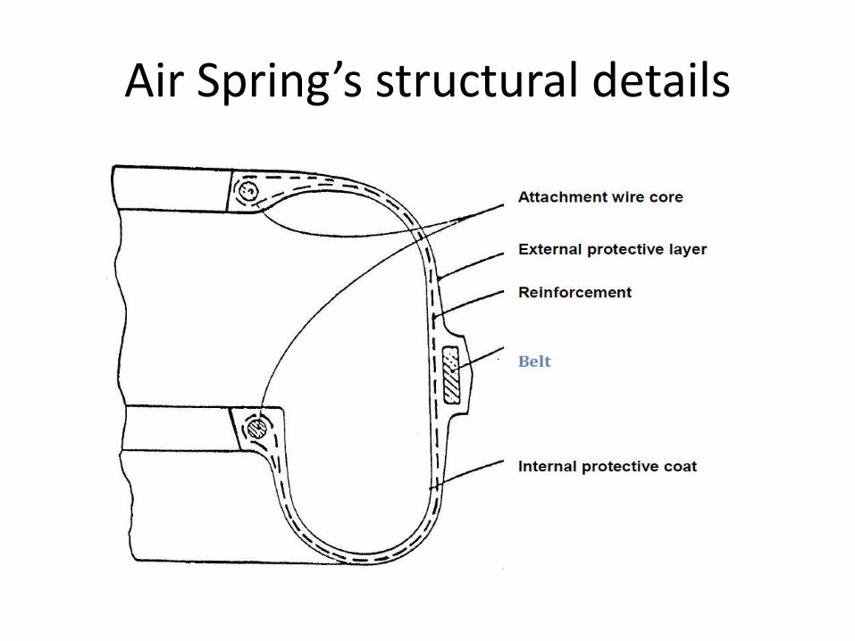
Air Spring’s structural details

Levelling valve’s delayed reactions

Air spring’s working principle

Air spring adjusting deflections

Air Suspension spring loads

Air suspension spring overloaded

Height adjustment

Air suspension spring offloaded
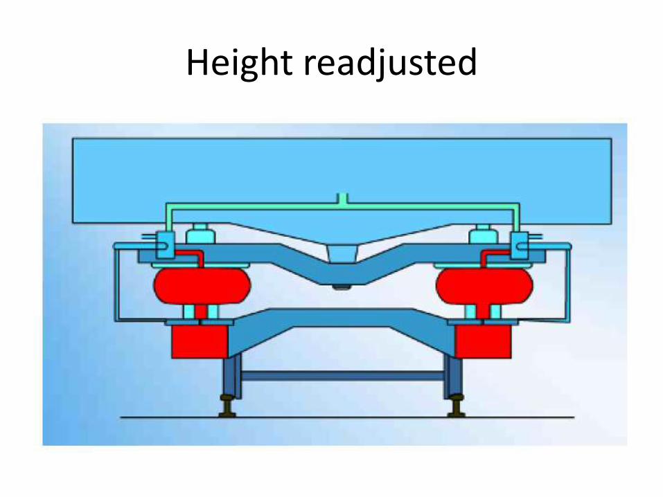
Height readjusted

Air spring technical parameters

Air spring testing at 6 bars {gauge}: Inflation heights {255-260}mm

Air spring rubber bellow wall structure

Duplex Check Valve
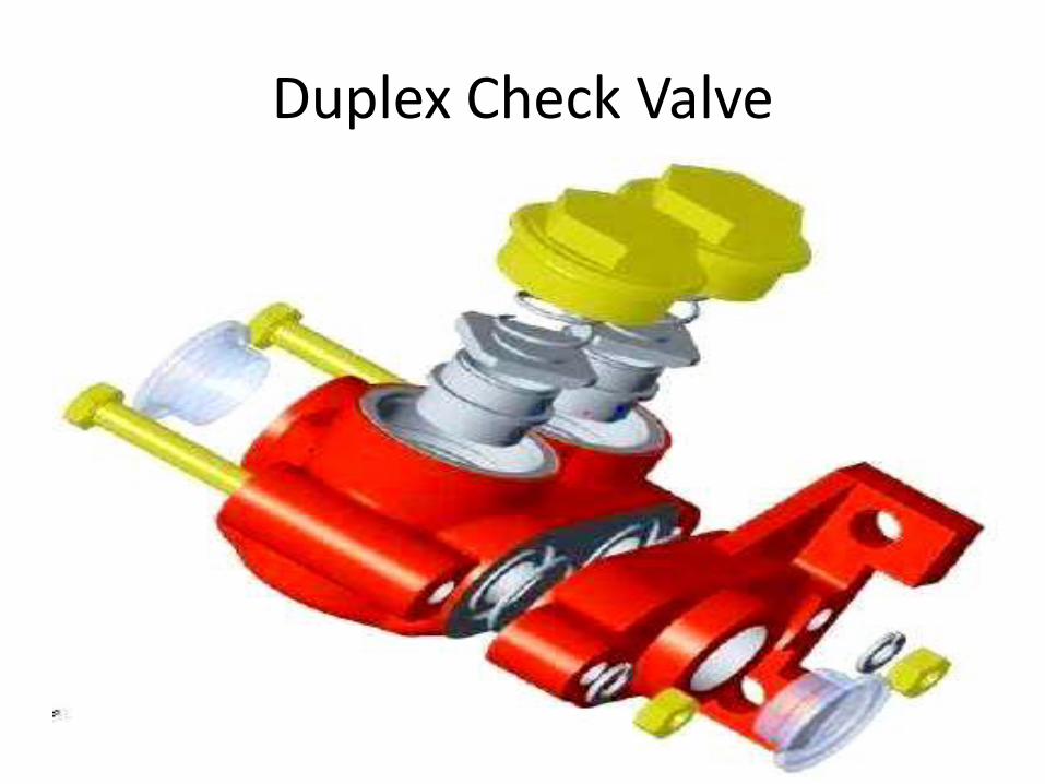
Duplex Check Valve

Levelling valves

3 – POINT AIR SUSPENSION SYSTEM
AS
DUPLEX
CHECK
VALVE
INSTALLATION
LEVER
ISOLATING COCK FOR
AIR-SUSPENSION
TWO WAY DIRT
COLLECTOR
AS
CHECK
VALVE
MAIN RESERVOIR PIPE LINE
INSTALLATION LEVER
LEVELING VALVE
20
LTR
S. R
ESER
VO
IR
20
LTR
S. R
ESER
VO
IR
150
LT
RS
.
RE
SE
RV
• In this system the bellow of one bogie is controlled by individual levelling valves. • But the bellows of other bogie are controlled by only one leveling valve. PNEUMATIC OPERATION
UNBALANCE BALANCE
MAIN RESERVOIR PIPE LINE
LEVELING
VALVE
LEVELING VALVE
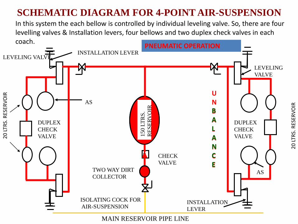
SCHEMATIC DIAGRAM FOR 4-POINT AIR-SUSPENSION
DUPLEX
CHECK
VALVE
AS
DUPLEX
CHECK
VALVE
INSTALLATION
LEVER
ISOLATING COCK FOR
AIR-SUSPENSION
TWO WAY DIRT
COLLECTOR
AS
CHECK
VALVE
INSTALLATION LEVER
20
LTR
S. R
ESER
VO
IR
20
LTR
S. R
ESER
VO
IR
15
0 L
TR
S.
RE
SE
RV
OIR
In this system the each bellow is controlled by individual leveling valve. So, there are four levelling valves & Installation levers, four bellows and two duplex check valves in each coach.
PNEUMATIC OPERATION
UNBALANCE
BALANCE

Air Brake system controls & Cut off Angle Cocks
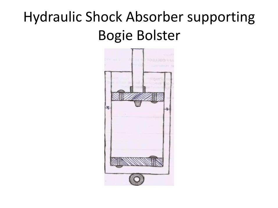
Hydraulic Shock Absorber supporting Bogie Bolster

ICF Axleguide Dashpot
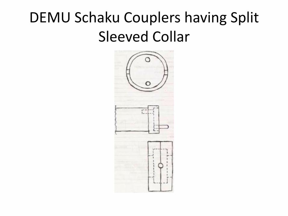
DEMU Schaku Couplers having Split Sleeved Collar

ICF DEMU Solebar Cambering
• +12 mm hogging camber at headstock ends
• 0 mm hogging/sagging at Body Bolster points
• +24 mm hogging camber at carriage centreline
• -10 mm deflection at headstock ends in reverse solebar cambering
• -20 mm deflection at carriage centreline in reverse solebar cambering

SS EMU/DEMU

New SS EMU/DEMU by BEML

SS EMU BEML

SS EMU Design
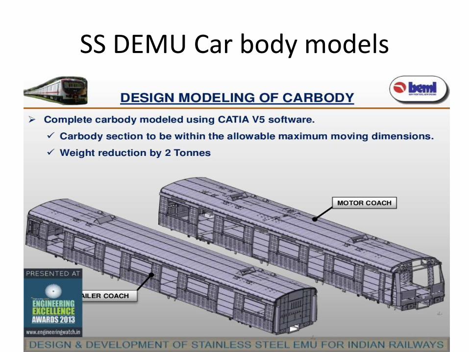
SS DEMU Car body models

SS DEMU furnishing development
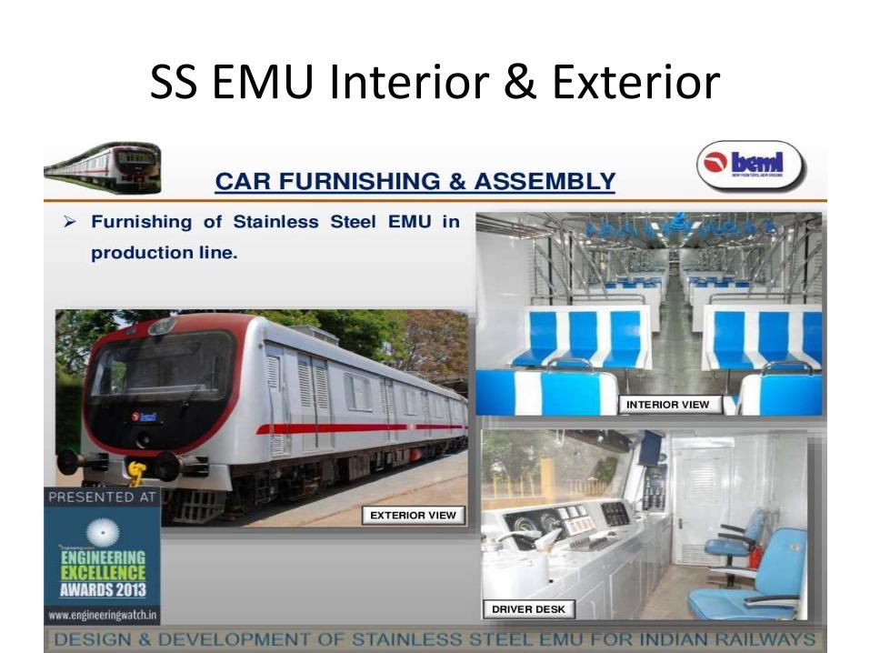
SS EMU Interior & Exterior

SS DEMU DPC & TC

SS DEMU TC & DPC

SS DEMU Manufacturing by BEML

SS DEMU Underframe, Roof & Body walls manufacturing by BEML

SS DEMU fabrication infrastructures

SS EMU Production planning

RDSO/RITES passed SS EMU at BEML

SS EMU 1st Prototype Rake

THANKS