demu fixing anchors eta t-fixx 12/15-e -...
TRANSCRIPT

ETA_T-FIXX 12/15-EDEMU FIXING ANCHORS
CONCRETE

DEMU FIXING ANCHORS T-FIXX
Genera l note
This approval only applies to original HALFEN products manufactured by HALFEN. The specifications in this approval are not transferable to other products. Users are fully liable for personel injuries and material damage caused by third-party products used instead of HALFEN products.
Use of third-party products

Deutsches Institut
für BButechnlk DlBt
Approvtll body for eOl1struetlon produets alld types of tOllstnlellon
Btlutcehnisehes Prüfalllt
An Institution estoblishod by the Fedcral allel Lacndcr Governmcnts
European Technical Assessment
* * * OosJgnatcd
* according 10 * Articlo 29 01 Regula·
* Hon (EU) No 30512011 * and member 01 EOTA
(Europoan Organl.
* saUon forTechnlcal * Assessmonl)
* * *
ETA-13/0222 of 4 December 2015
Mambar of
www.cota.cll
English translation prepared by DI Bt - Original version in German language
General Part
Technical Assessment Body issuing the European Technical Assessment:
Trade name of the construction product
Product family to which the construction product belongs
Manufacturer
Manufacturing plant
This European Technical Assessment contains
This European Technical Assessment is issued in accordance with Regulation (EU) No 305/2011, on the basis of
Deutsches Institut für Bautechnik
Deutsches Institut für Bautechnik
DEMU Fixing anchor T-FIXX
Cast-in anchor with internal threaded socket
Halfen GmbH Liebigstraße 14 40764 Langenfeld DEUTSCHLAND
HALFEN Herstellwerke
15 pages including 3 annexes which form an integral part of this assessment
European Assessment Document (EAD) 330012-00-0601
Kolonnenstraße 30 B 1 10829 Berlin 1 GERMANY I Phone: +493078730-0 I Fax: +493078730-320 I Email: [email protected]
Z69717.15 8.06.01-265/15
European Technlcal Assessmen! ET A-13/0222 English translalion prepared by DIBt
Deutsches Institut
für Bautechnik DlBt
Page 2 of 15 I 4 December 2015
The European Technical Assessment is issued by the Technical Assessment Body in its official language. Translations 01 this European Technical Assessment in other languages shall lully correspond to the original issued document and shall be identified as such.
Communication 01 this European Technical Assessment, including transmission by electronic means, shall be in lull. However, partial reproduction may only be made with the wrilten consent 01 the issuing Technical Assessment Body. Any partial reproduction shall be identified as such.
This European Technical Assessment may be withdrawn by the issuing Technical Assessment Body, in partieular pursuant to inlormation by the Commission in accordance with Article 25(3) 01 Regulation (EU) No 305/2011.
Z69717.15 8.06.01-265/15
Deutsches Institut
für Bautechnik DlBt
European Technlcal Assessmen! ETA-13/0222 Page 3 of 1514 December 2015
English translation prepared by DISt
Specifie part
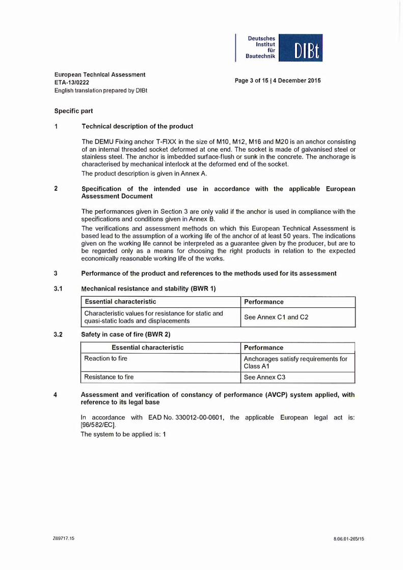
1 Teehnieal description of the product
The DEMU Fixing anehor T-FIXX in Ihe size of M10, M12, M16 and M20 is an an chor eonsisling of an inlernal lhreaded socket deformed al one end. The sockel is made of galvanised steel or slainless sleel. The anehor is imbedded surfaee-flush or sunk in Ihe eonerele. The anehorage is eharaelerised by meehanieal inlerloek al Ihe deformed end of Ihe socket. The produel descriplion is given in Annex A.
2 Speeitieation of the intended use in aeeordanee with the applicable European Assessment Document
The performances given in Seetion 3 are only valid if the anehor is used in complianee wilh Ihe speeifiealions and eondilions given in Annex B. The veriliealions and assessmenl melhods on whieh Ihis European Teehnieal Assessmenl is based lead 10 Ihe assumplion 01 a working lile 01 Ihe anehor 01 al leasl 50 years. The indiealions given on Ihe working lile eannol be inlerpreled as a guaranlee given by Ihe producer, bul are 10 be regarded only as a means lor ehoosing Ihe righl produels in relalion 10 Ihe expeeled eeonomieally reasonable working lile 01 Ihe works.
3 Pertormanee of the product and reterenees to the methods used tor ils assessment
3.1 Mechanieal resistanee and slability (BWR 1)
Essential charaeteristic
Charaelerislie values for resislanee lor slalie and quasi-slalie loads and displaeemenls
3.2 Safety in case of fire (BWR 2)
Essential eharaeteristic
Reaelion 10 fire
Resislanee 10 lire
Performance
See Annex C1 and C2
Performance
Anehorages salisly requiremenls lor Class A1
See Annex C3
4 Assessment and verifieation of eonstancy of performance (AVCP) system applied, with referenee to its legal base
269717.15
In aeeordanee wilh EAD No. 330012-00-0601, Ihe applieable European legal ael is: [96/582/EC). The syslem 10 be applied is: 1
8.06.01-265/15

European Technlcal Assessment ET A-13/0222
English translation prepared by DIBt
Deutsches Institut
für Bautechnik DIBt
Page 4 of 15 I 4 December 2015
5 Technical details necessary for the implementation of the AVCP system, as provided for in the applicable EAD
Technical details necessary for Ihe implementation of the AVCP system are laid down in the control plan deposited with Deutsches Institut fOr Bautechnik.
Issued in Berlin on 4 December 2015 by Deutsches Institut fOr Bautechnik
Uwe Bender beglaubigt: Head of Department Tempel
Z69717.15 8.06.01-265/15

Page 5 01 European Technlcal Assessment ETA-13/0222 01 4 December 2015
English translation prepared by DIBt
DEMU T-FIXX
eonerete member
fixture
serew
washer
data ell� tw --
Deutsches Institut
für Bautechnik
T-FIXX
��_, ____________ h�n�o�ln� ____________ 1
h = thiekness of conerete member
tfix = thiekness of fixture
tw = thiekness of washer
hnom = embedment depth
DEMU Fixing anehor T-FIXX
Prodllct description Instalied condition
Z69829.15
11
DlBt
Annex A1
8.06.01-265115

Page 6 01 European Technlcal Assessment ETA-13/0222 01 4 December 2015
English translation prepared by DIBt
dnom
d ----I
,
I I ,
/ T , , , / / / / / / , / , / / / / /
/
/,� J �!�
d2 - -
E E N
:5 ...J
...J
Deutsches Institut
für Bautechnik
:g: u .lll '" -0 'ö � .s:;: .2' Q) :S
I
DlBt
There are two different materials available tor the DEMU Fixing anchor T-FIXX:
Material 1: Fixing anchor in galvanised steel
Material 2: Fixing anchor in stainless steel
TableA1: Dimensions 01 DEMU Fixing an chor T-FIXX
d dnom L� d, Thread Material 1 Material 2 Material 1 + 2 Material 1 Material 2 Material 1 [Olm] [mml [Olm] [Olm] Imm Imml Im 011 M10 13.5 13.5 10.4 - 13.6 18.1 17.3 50/75 M12 17.0 17.2 12.5-16.1 23.0 23.0 50170/95 M16 21.3 21.3 16.1 -22.1 29.1 28.0 60/100/125 M20 26.9 26.9 20.2 - 27.6 34.7 33.5 70/100/145
DEMU Fixing anchor T-FIXX
Product description Dimensions
Z69829.15
L Material 2
Imml 50/65
50170/115 60/801110
70/100/125
Annex A2
8.06.01-265f15

Page 7 01 European Technlcal Assessment ETA-13/0222 014 December 2015
English Iranslation prepared by DIBI
®
DEMU T-FIXX M ...
Table A2: SpoclllcaUon and material of fixing anchor
lIem Component
2
.0308 (E235) 1 1. , 1.0044 (5275) /1.0533 (E295) /1.0570 (5355) /
Fixing anchor .0580 (E355) /1.0255 (P235TR2) ace. EN 10305-1,
Data clip
or -3, all delivery condltlon +N, I 1)
1 : 2:
Deutsches Institut
für Bautechnik
Marking:
DIBt
e.g.: DEMU T-FIXX M10x50 GV
DEMU: identifying mark of the producer
T-FIXX: name of the anchor
M 1 Ox50: size
GV: material
Material:
GV: galvanised steel
A4: stainless steel
Table A3: Speciflcation and matellal of fixing components I suppl. relnlolcement (not Included w ith the fixing system)
Appr. Componenl
Washer
Sc rew
Suppl. relnforcemonl
Material 10r usa with fixing ancllors
made of malerial 1
Sieal acc. EN 10025, galvanised I)
D'men,'ons nce. EN 150708917093-1
Steal ace. EN ISO 898-1, galvanised 11, ,trongÜ1 grade 4.6, 5.6 or 8.8
B500A or 85008
De\ailing ace. CENITS 1992-4:2009
"thickness of caeUng � 5IJm ace. EN ISO 4042
Material lor use wilh fixing anchors
made of material 2 Slainlo" '10011.4401/1.4404/1.4571/1.4362 1 1.4578/1.4062/1.4162/1.4662/1.4439/1.4462/ 1.4539/1.4565/1.4529/1.4547, ace. EN 10088
Slainloss '10011.4401/1.4404/1.4571/1.4362/ 1.4578/1.4062/1.4162/1.4662/1.4439/1.4462/ 1.4539/1.4565 /1.4529/1.4547, ace. EN ISO 3506-1, ,trongÜ1 grade M-50, M-70 or M-80 ISlalnloss reinforeomenl slool rospoet. B500A or 85006 meeting Ü10 requirements (ar conerete cover
Cn.naee. EN1992-1
Data clip: 5ection and top view (with example for marking)
DEMU Fixing anchor T-FIXX
Producl descriplion Marking and materials
269829.15
Annex A3
8.06.01-265115

Page 8 01 European Technlcal Assessmen! ETA-13/0222 01 4 December 2015
English translation prepared by DIB!
Specifications of Intended use
Anchorages sub)ect to: • Statie and quasi-statie loads. • Fire exposure: only for eonerete C20/25 to C50/60.
Base materials:
Deutsches Institut
tür Bautechnik
Reinforeed or unreinforeed normal weight eonerete aecording to EN 206:2013. • Strength elasses C20/25 to C90/105 aeeording to EN 206:2013.
Craeked or uneraeked eonerete.
Use condltlons (Envlronmental condltlons) • Anehorages subjeet to dry internal eonditions (material 1 and 2 ace. Annex A3).
DlBt
External atmospherie exposure (ineluding industrial and marine environment), or exposure in
permanently damp internal conditions, If no particular aggressive conditions exist (material 2 ace. Annex
A3).
Note: Partieularly aggressive eonditions are e,g. permanent alternating immersion in seawater or the
splash zone of seawater, chloride atmosphere of indoor swimming pools or atmosphere with extreme
ehemieal pollution (e.g. in desulfurization plants or road tunnels, where de-ieing materials are used).
Design:
Anehorages are designed under the responsibillty of an engineer experieneed in anehorages and
eonerete work.
• Verifiable ealeulation notes and drawings are prepared taking aecount of the loads to be anehored. The
position of the anehor is indieated on the design drawings (e. g. position of the anehor relative to
reinforeement or to supports, ete.).
Anchorages under statie or quasi-statle aetions are designed in aeeordanee with:
- CEN/TS 1992-4:2009, part 1 and 2 • Anehorages under fire exposure are designed in aeeordanee with:
- CEN/TS 1992-4:2009, part 1, Annex 0 (Ioeal spalling of the eonerete cover must be avoided)
The serew is chosen with corresponding serew-in length ace. to Annex B2, Table B1 and with the
strength elass ace. to Annex Cl and C2 subjeet to the required steel resistanee and with the material
ace. to Annex A3, Table A3.
Installation: • Anehor installation earried out by appropriately qualified personnel and under the supervision of the
person responsible for teehnieal matters of the site.
Use of the anehor only as supplied by the manufaeturer without any manipulation or exehanging the
components. • The anehors are fixed on the formwork so that no movement of the anehors will oeeur du ring the time
of laying the reinforeement and of plaeing and eompaeting the conerete. • Adequate compaetlon elose to the anehor particularly at head of the bolt, e. g. without slgnifieant voids.
The cast-in anehor is protected against ingress of eonerete into the threaded socket. • The setting torques given in Annex B2 are not exeeeded. • The inner area of the socket of the anehor made of galvanlsed steel has to be protected agalnst Ingress
water.
DEMU Fixing an chor T-FIXX
Intended use Specifications
Z69829.15
Annex B1
8.06.01-265/15

Page 9 of European Technlcal Assessment ETA-13/0222 of 4 December 2015
Ellglish translation prepared by DIBt
Direel eenlael belween fixlure and dala clip
The fixlure is braeed le Ihe dala clip, if neeessary by suilable washers.
General applicalien
The fixlure is braeed le Ihe eenerele, Ihe fixing aneher being embedded flush er reeessed in Ihe eenerele.
ble 81: Installation parameters
IM.,lmum screw-in length
DEMU Fixing aneher T-FIXX
Intended use
L$d,mal(
d,
Positions 01 the lixture, installation parameters
Z69829.15
Deutsches Institut
für Bautechnik
I I) lenglh Dlllicraw Ls
DIBt
1) tw + t"x + Lsd,min � Ls :s; tw + tfl)( + LSd.max
2) Iw + I,,, + Iv + L'd.min " L, " Iw + I,,, + Iv + L'd.max
32.0
12.0 14.0 18.0 22.0
Annex 82
8.06.01-265/15

Page 10 of European Teehnleal Assessment Deutsches ETA-13/0222 of 4 Deeember 2015 Institut
für English translation prepared by DIBt Bautechnik
�Smln C!:Smlo
DlBt
The mentioned spacings, edge distances and member thicknesses apply also for fixing anchors installed in the front edge.
Table B2: Mln. aliowed thlckness of concrete mamber, rnln. edge dlstanees and spaclng
Thread d mml M10 M12 M16 M20 Mlnlmium spaelng Smo [mm] 100 100 100 120 Minimum edge dlslance emin [mm] 50 50 50 60
Minimum thlckness of concrele member hmln HOlm] hnom + Cnom l}
"c""", acc. EN 1992-1 wilh c""'" � 20mm For fixing anchors made of slainless sleel a minimum concrele cover c""'" = 20m m is suflicient.
DEMU Fixing anchor T-FIXX
Inlended use Annex B3
Arrangement of fixing anchors and member Ihickness
Z69829.15 8.06.01-265/15

Page 11 of European Technlcal Assessmen! ETA-13/0222 of 4 December 2015
English translation prepared by DIBt
Installation instruction - part 1
1. Sccpe 01 delivery
2. Fixing 01 the anchor to the lormwork
1"11 ,j "" -,
-=-::1:' • ., •
3. Pouring and ccmpacting 01 concrete
DEMU Fixing anchor T-FIXX
Intended use Installation instruction - part 1
Z69829.15
Deutsches Institut
tür Bautechnik DIBt
1) Selection 01 lixing anchor in accordance with the planning documents.
1a) DEMU T-FIXX made 01 galvanised steel (GV) or stainless steel (A4)
1b) Data clip lor T-FIXX GV, colour: grey Data clip lor T-FIXX A4, colour: white
1) Attach data clip to the fixing anchor.
2) Fix the anchor to the lormwork with the help 01 DEMU assembly accessories (e. g. nailing plate) or alternatively by hexagon bolts.
---> The inside 01 the threaded socket must be protected against ingress 01 dirt and water.
3) II necessary, supplementary reinlorcement has to be placed according to the planning documents.
1) Pour concrete carelully, make sure the anchor stays in place!
2) Compact ccncrete carelully, avoid direct contact between compacting device and an chor.
---> The anchor must not be moved by lorce or damaged!
Annex B4
8.06,01-265/15

Page 12 of European Technlcal Assessmen! ETA-13/0222 of 4 December 2015
Eng/ish translation prepBred by DIBt
Installation instruction - part 2
Deutsches Institut
tür Bautechnik DlBt
4. Hardening of the concrete, striking the formwork
5. Mounting of fixture
6. Maximum torque moments
. ,
DEMU Fixing an chor T-FIXX
Intended use Installation instruction - part 2
Z69829.15
1) Remove assembly accessories and forrnwork.
2) Check if the inside of the threaded socket is free from dirt, otherwise clean it; further protection against ingress of water, dirt, etc. until required for use.
1) Make sure that the concrete has reached its final strength.
2) Check the length of the required bol!. --> Maximum I minimum screw-in length according
Annex B2!
3) Mounting of the fixture ---+ Use fixing components according Annex A3,
Table A3. -. Maximum torque moments, see table below! --> Take additionally care of assembly advices
for the fixture.
Apply torque moment with the help of a torque wrench. Tinst must not be exceeded.
Maximum torqua moment Ttn ..
Thread Id IImmll M10 I M12 I M16 I M20 Max. torque moment I max. T.SI IINm) I S 8 I S 10 I S 30 I S 60
Annex 85
8.06.Q1-265115

Page 13 01 European Technlcal Assessment ETA-13/0222 014 December 2015
English Iranslation prepared by 0181
Table C1: Characterl5tlc valuoslor tension loads
'hre .. 10 Imm Sloollollu,o, fixing da 0 . sieel sl,onglh 4.6) m,'
IN,... II IkN) Partl,1 sofolV faelo, 1-) Iv"," II
M'O I I sleel 17.5
Deutsches Institut
für Bautechnik
I M,2
I 29,2
OIO."."u'O, IIx'ng aneoo, ano screw (m'n. Slee' Slreng . maOa 01 Slaln'e" Sleel '0 A4{j01
IN" .• IikN) I 24.9 Partial s.fetV faclo, Iv, .. " Ii-) 2.79 �folhrro, fix'ng aneho' and serow (mln. Sleel slrenglh A'-70) mada of stalnlo" Sloel
Partl,1 sololV laclo,
'IXlng a� I I Charaet. , In eraeked eonerele Charael. 'In j eonerole Fixing ancho, In slalnlO" steel Charael. , In craeked conerele Charaet. lin' j conere'e
I factors 10r NR�,p In cracked and concrale
Partial solelv laelo,
,cono fallu,o
Etfecti\!3 enchorage depth
IN".. IIkN) 24.9
Iv"," 11-)
C20/25 IN". . IikN) 17.1 C20/25 IN" .. IikN) 2'.0
C20/25 I" .• kN) 13.8 C20/25 ".' kN) 19.3 <0''''0 <0'01" <0,,,,, <0'0/00 <0'''55 <050160
V,. "
IM'O,"O: 43. IM10x85": 58.
111" Ilmm) .Ml0x75": 68.7
I Factor 10 Illk� Into account the Innuance of load transter Ik" 11-1 I i In cracked and uncracked concrale Ik� , 11-)
: spaclng Is" ... Ilmm) i : edgo dlslanee Ic" , .. Ilmm)
IPortlal safolV focto, Iv" " 11-1
I ; of cone,ele momber " Ilmm) I: spacing IS",,. Ilmm) I: edgo dlslaneo Ic"" . Imm)
IPartlal .. felv faclo' IV",. " 1-)
I "In absence of olher national I ; "onlv slalnfoss steel; " onlv ' I lsloel
ITable C2: Dispiacemonis under tension loads
IThroad Imm) Ml0 ITonsion load IkN) 7 IShorlUm. , I Ö", ImOl) 0 3 Ilong timo, i I ö,,_ Imm) 0.6
DEMU Fixing anchor T-FIXX
Performances
42.2 2.86
43.5
28.3 39.6
I 27.5
I 38.5
IMl2x70:
iM12x115": -
M12 12 0.5 1.0
Characteristic values for tension loads, displacements lInder tension loads
Z69829.15
DIBt
I M'6 I M'O
I 47.4 I 61.4 1.7'
I 69.7 I 90.3
I 2.79
I 69.7 I 90.3 2.79
I '6.3 I 56.6
I 64.8 I 79.2
38.9 47.0 54.5 I 65.7
.20 1.48 1.80 2.00 2.20 2.40 1.50
.,. IM'OX/O: 61.' 71.3 91.2
: 116, : 136.
. 116. -8.5
11.9 3.0' 11" 1.5' 11"
1.50
2.0' h"
6.0' 11" 3.0' h"
1.50
M16 M20 19 25 0.3 0.2 0.6 0.4
Annex C1
8.06.01-265/15

Page 14 of European Technlcal Assessment ETA-13/0222 of 4 December 2015
English Iranslation prepared by 0181
Deutsches Institut
für Bautechnik DlBt
ITable C3: Choracterlstlc vnlues ror shear loads
!up Id 11010111
'Wl1hOUI I ; 1992·4·2, 6.3.3.1) Ik, 11'1 ISleel f,l1ure, fixing anchor ond ,cr.w (mln. SIeei, ) mod. of, Iv". l[kNI lPartial Iv." 11'1
M10
, Sle.1 6.8
ISle.' f,lIure, fixing ,nehor and ,cr.w (mln. Sleel Slrenglh �4-50) mede of ,"'n'e" Sleel I IV".. IIkNI 12.5
1P0rt�1 Iv." 11-1 2.33 IStool falluro, fixing .nchor and ,crew (mln. ,teel ,'reng'h �4-70) m,d. 01 "laini." ,'eel
i I IV"., IlkN] 12.5 IP.rt�1 ,.f.ty faclor Iv." 11-1
1siieärl0'dS wlth lever arm 1SiOCIT,lIure, , r 'nd $Crew (mln. ,'eel ,'r.ng'h 1.6) made I I" eel
I
I I I
I IM""" IINm] 29.9 I IPart1a1 safety faclor Iv", 11-1 ISt.ell.llure, I ,crew (mln. Sloel ,'reng'h i.6) made of I I 1" •• 1
I IM""., IINm) 37.4 I IParllal,.fetyfaclor Iv." '. 11,] ISle.1 fplluro, fixing I 'cr.w (mln. Sle.' ,'reng'h 1.8) made of I I I
I IM"".. IINm) 66.9 I IParl�1 ,ol.ty factor Iv." 11') 1.45 I
I . ".el Slr.nglh .\4-50) mad.· I s Sleel I IM"
".. IINm] 37.4 I Porl�1 saf.ty faclor 'V'" ., 1[·)
I I
M12
14.6
21.1 2.38
21.6
1.0
I 23.7 1.45
I 34.6
I I 34.6 2.33
52.4 I 133.2 1.67
65.5 I 166.5 1.67
104.6 I 263.6 1.25 I 65.5 I 166.5
2.36
I
I 2.33
I
I
I
I 1.45
I
30.7
45.1
45.1
259.6
324.5
541.4
324.5
I
Part�1 saf.ty factor M" "., IINm) 52.3 I 91.7 I 233.1 I 454.4
I
Partial ,al.ty factor
V"," 11·) 1.56
M'"" IINm) 101.3 I 104.6 I 366.0 I 796.2 V," " 11-1 2.33 I 1.33 I 2.33
2.' 116X! ''': 2. Foclor k, [.] C': 2.(
Partial safety faclor
,edge f,lIur. (wl!hout ,uPPt I
lenglh of fixing anchor (for shear loads)
, diameter Parl�1 ,alety factor
V'" '
I.
11')
1 10101]
110101) 11-1
IM10x50: 30. IM12x50: . 45.cIM12x70: . 55.
IM12x115": .
13.5 17.0/17.2 ')
1.50
1.50
� 2.
46. 76�
. 77.0[M20x125": 101.
. 102.' • 21.3 26.9
121.
, In ab,enc. of othar nallonal , : "only ,tainies, ,t •• I; "only! , ,'ael; ., highar' I I , for slalnlas"teel
lable C4: DIsplacements under sheer loads
Thread d Olm M10 M12 M16 M20 Shear load V kN 13 19 24 28 Shor! time dlsplacemenls 6.. [Olm] 2,0 2.0 2.0 3.0 lang time displacements öv- [Olm] 3.0 3.0 3.0 4.5
DEMU Fixing anchor T-FIXX
Performances Annex C2
Characteristic values for shear loads, disp[acements lmder shear loads
Z69829.15 8.06.01-265/15

Page 15 of Eu,opean Technlcal Assessmen! ETA-13/0222 of 4 Decembe, 2015
English Iranslation prepared by 0181
Table e5: Characterlstlc va lues lor reslstenee to flre
Thread slze d Hmm Ml0 Steel fallure 'or tension end shear load (FRII,I,II = NRk, •• !! = VRk .. ,I')' fixina anchor end screw made of aalvanised steel
R30
Characterlstic resistence R60
R90
R120
Partial safety factor
R30
Characteristlc reslstance R60
R90
R120
Partial salety laclor
FRII.I,h FRII.I.fi FRk .•. fi FR� .• .f' VM',fi I) M Rk, • .11
MUR",.f' M Rk .• .t. MURk .• .,i
V/'b.h
[kNJ 0.8
[kNJ 0.7
[kNJ 0.5
[kNJ 0.4
[-J [NmJ 1.1
[NmJ 1.0
[NmJ 0.7
[NmJ 0.6
[-J Steal fallure for tension end sheer load (FRII .•. II = NRk,s,tl = Vnk .. ,,,), fixing an chor end screw made of stainless steel
R30
CharacterisUc resistence R60
R90
R120
Partial safety factor
R30
Charecteristic reslstance R50
R90
R120
Partial safety faclor
Pull-oul lallur.
Characteristic reslstance I R90
I R120
Partial sarety raclor
Concrete co ne 'ellure
Characterisllc resistance I R90
I R120
Characteristlc spaclng
Characteristlc edge dlstance
Partial salety laclor
Concrel. p'y-oul lollu'.
Characleristic r9slstance I R90
I R120
Partial solety laclor
Concrete edge tellure
Characteristic reslstence R90
R120
Partial ,alely laclor
'/ In absence of other national reoulations
DEMU Fixing anchor T-FIXX
Performances
FR� .•. fi FRk,l.n FRk,I.1i FRk."� Yl.b.fl 'I MU Rk.t}' M RI. .• ,f1 M Rk,." MU RII .• J,
V,.b.� 'I
NR�p.r1 NR�p,f1 VMP.� 'I
NR�.e.'i NRk.e.1i Str.I(� Ccl.IU YMeJ,'J
VRk,cp.n VRk,cp.li YMe.fl"
VR�.e,(r VRk.eJi YMe." "
Characte,istic values for resistance to fire
Z69829.15
[kNJ 1.2
[kNJ 1.0
[kNJ 0.8
[kNJ 0.7
[-J [NmJ 1.9
[NmJ 1.5
[NmJ 1.2
[NmJ 1.0
[-J
[kNJ [kNJ [-J
[kNJ [kNJ [mmJ [mmJ [-J
[kNJ [kNJ [-J
[kNJ [kNJ [-J
I
Deutsches Institut
für Bautechnik
M12
1.7
1.3
1.1
0.8
1.00
2.6
2.0
1.7
1.3
1.00
2.5
2.1
1.7
1.3
1.00
3.9
3.3
2.6
2.1
1.00
,
DlBt
M16
2.8
2.1
1.8
1.4
6.7
5.0
4.3
3.3
4.2
3.5
2.8
2.2
10.0
8.3
5.7
5.3
NRk p,f.(iO) = 0.25 • NRk p NRl.p,f.(120) = 0.20 • NRk p
1.00
NU Rk.e.r(�) - hel200 • W Rk.e S NU Rk.e NURk.e.f.('ZO) = 0.8 • he�200 • NU Rk,e S NURk.<:
4.0' h�f
2.0· her
1.00
VRk.cP.I"(9G) = k, • NRk.eJ�9G) VRk.CflJ(120) = k, • NRk,e.r(120)
1.00
V'Rk.<:.f(90) = 0.25' V'Rk,e V"Rk.e.r(1201 = 0.20' VRke
1.00
M20
3.6
2.7
2.3
1.8
13.0
9.7
BA 6.5
5.4
4.5
3.6
2.9
19.5
16.2
13.0
10.4
Annex C3
8.06.01-265/15

NOTES REGARDING THIS CATALOGUETechnical and design changes reserved. The information in this publication is based on state-of-the-art technology at the time of publication. We reserve the right to make technical and design changes at any time. HALFEN GmbH shall not accept liability for the accuracy of the information in this publication or for any printing errors.
The Quality Management System of Halfen GmbH is certified for the locations in Germany, France, the Netherlands, Austria, Poland, Switzerland and the Czech Republic according to DIN EN ISO 9001:2008, Certificate No. QS-281 HH.
Furthermore HALFEN is represented with sales offices and distributors worldwide. Please contact us: www.halfen.com
Austria HALFEN Gesellschaft m.b.H.Leonard-Bernstein-Str. 101220 Wien
Phone: +43 - 1 - 259 6770 E-Mail: [email protected]: www.halfen.at
Fax: +43 - 1 - 259 - 6770 99
Belgium / Luxembourg HALFEN N.V.Borkelstraat 1312900 Schoten
Phone: +32 - 3 - 658 07 20E-Mail: [email protected]: www.halfen.be
Fax: +32 - 3 - 658 15 33
China HALFEN Construction Accessories Distribution Co.Ltd.Room 601 Tower D, Vantone CentreNo. A6 Chao Yang Men Wai StreetChaoyang District Beijing · P.R. China 100020
Phone: +86 - 10 5907 3200E-Mail: [email protected]: www.halfen.cn
Fax: +86 - 10 5907 3218
Czech Republic HALFEN s.r.o.Business Center ŠafránkovaŠafránkova 1238/1155 00 Praha 5
Phone: +420 - 311 - 690 060E-Mail: [email protected]: www.halfen-deha.cz
Fax: +420 - 235 - 314 308
France HALFEN S.A.S.18, rue Goubet75019 Paris
Phone: +33 - 1 - 445231 00E-Mail: [email protected]: www.halfen.fr
Fax: +33 - 1 - 445231 52
Germany HALFEN Vertriebsgesellschaft mbHLiebigstr. 14 40764 Langenfeld
Phone: +49 - 2173 - 970 - 0E-Mail: [email protected]: www.halfen.de
Fax: +49 - 2173 - 970 225
Italy HALFEN S.r.l. Soc. UnipersonaleVia F.lli Bronzetti N° 2824124 Bergamo
Phone: +39 - 035 - 0760711E-Mail: [email protected]: www.halfen.it
Fax: +39 - 035 - 0760799
Netherlands HALFEN b.v.Oostermaat 37623 CS Borne
Phone: +31 - 74-267 14 49E-Mail: [email protected]: www.halfen.nl
Fax: +31 - 74-267 26 59
Norway HALFEN ASPostboks 20804095 Stavanger
Phone: +47 - 51 82 34 00E-Mail: [email protected]: www.halfen.no
Fax: +47 - 51 82 34 01
Poland HALFEN Sp. z o.o.Ul. Obornicka 28760-691 Poznan
Phone: +48 - 61 - 622 14 14E-Mail: [email protected]: www.halfen.pl
Fax: +48 - 61 - 622 14 15
Sweden Halfen ABVädursgatan 5412 50 Göteborg
Phone: +46 - 31 - 98 58 00E-Mail: [email protected]: www.halfen.se
Fax: +46 - 31 - 98 58 01
Switzerland HALFEN Swiss AGHertistrasse 25 8304 Wallisellen
Phone: +41 - 44 - 849 78 78E-Mail: [email protected]: www.halfen.ch
Fax: +41 - 44 - 849 78 79
United Kingdom /Ireland
HALFEN Ltd.A1/A2 Portland CloseHoughton Regis LU5 5AW
Phone: +44 - 1582 - 47 03 00E-Mail: [email protected]: www.halfen.co.uk
Fax: +44 - 1582 - 47 03 04
United States of America HALFEN USA Inc.8521 FM 1976P.O. Box 547Converse, TX 78109
Phone: +1 800.423.91 40E-Mail: [email protected]: www.halfenusa.com
Fax: +1 877.683.4910
For countries not listed HALFEN International
HALFEN International GmbHLiebigstr. 14 40764 Langenfeld / Germany
Phone: +49 - 2173 - 970 - 0 E-Mail: [email protected]: www.halfen.com
Fax: +49 - 2173 - 970 - 849
CONTACT HALFEN WORLDWIDE
HALFEN is represented by subsidiaries in the following 14 countries, please contact us:
© 2
015
HA
LFEN
Gm
bH, G
erm
any
appl
ies
also
to
copy
ing
in e
xtra
cts.
B - 9
08 -
E - 1
2/15
PD
F 1
2/15