density of materials - fao.org
TRANSCRIPT


Density of materials
SINKING MATERIALS FLOATING MATERIALS
■ Metals ■ Wood Multiplication factor* Multiplication factor* Type Density
(g/cc) freshwater sea water Type Density
(g/cc) freshwater sea water aluminium 2.5 0.60 + 0.59 + bamboo 0.50 1.00- 1.05- brass 8.6 0.88 + 0.88 + cedar, red 0.38 1.63- 1.70- bronze 7.4 0.86 + 0.86 + cedar, white 0.32 2.13- 2.21- to 8.9 0.89 + to 0.88 + cork 0.25 3.00- 3.10- cast iron 7.2 0.86 + 0.86 + cypress 0.48 1.08- 1.14- to 7.8 0.87 + 0.87 + fir 0.51 0.96- 1.01- copper lead 8.9 0.89 + 0.88 + oak, dry 0.65 0.54- 0.58- 11.4 0.91 + 0.91 + oak, green 0.95 0.05- 0.08- steel 7.8 0.87 + 0.87 + pine 0.65 0.54- 0.58 - tin 7.2 0.86 + 0.86 + pine, Oregon 0.51 0.96- 1.01- zinc 6.9 0.86 + 0.85 + pine, poplar 0.41 1.44- 1.50- oplar 0.48 1.08- 1.14- spruce 0.40 1.50- 1.57-
DE
NSI
TY
OF
MA
TE
RIL
S
teak 0.82 0.22- 0.25- walnut 0.61 0.64- 0.68- ■ Textiles
Multiplication factor*
■ Fuel Type Density
(g/cc) freshwater sea water Multiplication factor*
aramide (kevlar) 1.20 0.17 + 0.15 + Type Density
(g/cc) freshwater sea water cotton 1.54 0.35 + 0.33 + petrol (normal or
super) 0.72 0.39 - 0.43- hemp 1.48 0.32 + 0.31 + petrol for lamps 0.79 0.27- 0.30- linen 1.50 0.33 + 0.32 + diesel fuel 0.84 0.19- 0.22- manilla 1.48 0.32 + 0.32 + crude oil, heavy 0.86 0.16- 0.19- polyamide (PA) 1.14 0.12 + 0.10 + crude oil, light 0.79 0.27- 0.30- polyester (PES) polyviny
1.38 0.28 + 0.26 + fuel oil, heavy 0.99 0.01- 0.04-
alcohol (PVA) polyvinyl
1.30 0.23 + 0.21 + fuel oil, intermediate
0.94 0.06- 0.09- chloride (PVC) 1.37 0.27+ 0.25 + (merchant vessels) polyvinylidene 1.70 0.41 + 0.40 + ramie 1.51 0.34 + 0.32 + ■ Textiles sisal 1.49 0.33 + 0.31 + Multiplicatie factor* ■ Other Materials
Type Density (g/cc) freshwater sea water
Multiplication factor* polyethylene 0.95 0.05- 0.08- Type Density
(g/cc) freshwater sea water polypropylene
0.90 0.11- 0.14 -
brick 1.9 0.47 + 0.46 + polystyrene, expanded
0.10 9.00- 9.26-
chalk 2.4 0.58 + 0.57 + concrete 1.8 0.44 + 0.43 + ■ Others to 3.1 0.68 + 0.67 + ice 1 0.95 0.11- 0.14- I earthenware 2.2 0.55 + 0.53 + oil 0.90-0.95 glass 2.5 0.60 + 0.59 + Examples of loss of buoyancy as a function of duration of immersion: rubber 1.0 0.00 0.03 - after 0 days 10 days 15 days
to 1.5 0.33 + 0.32 + cork 4.5 kgf 4.0
sandstone 2.2 0.55 + 0.53 + wood 2.0 kgf 1.0 0 stone 2.5 0.60 + 0.59 + ebony 1.25 0.20 + 0.18 +
' Multiplication factor used to calculate the weight in water' of different materials, as shown on page 4.

Weight in water, with examples for materials and
for a rigged gillnet
24.6 x 0.10( + ) = 2.46 kg flotation in sea water
■ Example c: Calculating the weight in water of a bottom gillnet
component weight(kg) in air
weight (kg) in sea water
ropes: 2 x 90 m PP Ø 6 mm
3.060 -0.430 -
netting: 900 x 11 meshes 140 mm stretched mesh PAR 450 tex with bolchlines 1.360 + 0.136 + floats: 46 corks x 21 g (in air) (or 50 floats of 60 gf each)
0.970 - 3.000 -
sinkers: 180 lead sinkers, 80g each (in air) (1 or 111 stones, avg. weight 200 g (2)
14.400
22.200
+13.100 +
TOTAL (1)19.790
DE
NSI
TY
OF
MA
TE
RIL
S
(2) 27.590 9.806 +
P = A x {1 - DW/DM}*
where : P = weight (kg) in water A = weight (kg) in air DW = density (g/cc) of water (freshwater
1.00; sea water 1.026) DM = density (g/cc) of material * The term in brackets, the multiplication factor, has been calculated for the materials most commonly used in fisheries, with the results given in the tables on pages 2-3. The factor followed by a + sign indicates a sinking force. The factor followed by a - sign indicates a buoyant or floating force. To obtain the weight in water of a certain quantity of material, simply multiply its weight in air by the factor. Example a: 1.5 kg of cork in air The table on page 3 gives the multiplication factor for cork:
freshwater : 3.00(-) sea water : 3.10( -)
so, 1.5 x 3.00(-) = 4.5 kg flotation in freshwater 1.5 x 3.10H = 4.65 kg flotation in sea water Example b: 24.6 kg of polyamide (nylon) in air The table on page 3 gives the multiplication factor for polyamide:
freshwater : 0.12( + ) sea water : 0.10( + )
so, 24.6 x 0.12( + ) = 2.95 kg flotation in freshwater
The weight of a gillnet in water is calculated by adding the weights of the different components, taking into account the sign of the factor. The sign of the total indicates the type of net we have made; thus, this gillnet with a + sign would be a bottom net with a sinking force of 9.806 kg.

Safe working load, breaking load, safety factor
■ Definitions ■ Safe working load — Safe working load (SWL), is the maximum load that an item is certified to lift in service. Another equivalent term in use is Working load limit. — Breaking load (BL) is the maximum load that an item can hold with a static load before it breaks. Another equivalent term in use is Breaking strength. — Safety factor
= breaking load safe working load
Very important : The loads used in these calculations are static loads. Dynamic or shock loads increase the stress considerably, and thus increase the possibility of breakage. ■ Values of the safety factor (a) For ropes
Diameter (mm) 3-18 20-28 30-38 40-44 48-100 Safety factor 25 (est) 20 15 10 8
STR
EN
GT
H O
F H
AR
DW
AR
E
(b) For wire ropes and metal hardware : safety factor about 5—6.

Synthetic fibres and commercial names ■ Polyamide (PA) ■ Polypropylene (PP) ■ Polyester (PES)
Akvaflex PP (Nor) Courlene PY (UK) Danaflex (Den) Drylene 6 (UK) Hostalen PP (Ger) Meraklon (Ital) Multiflex (Den) Nufil (UK) Prolene (Arg) Ribofil (UK) Trofil P (Ger) Ulstron (UK) Velon P (USA) Vestolen P (Ger) ■ Copolymers (PVD) Clorene (Fran) Dynel (USA) Kurehalon (Jap) Saran (Jap, USA) Tiviron (Jap) Velon (USA) Wynene (Can)
Dacron (USA) Diolen (Ger) Grisufen (E. Ger) Tergal (Fran) Terital (Ital) Terlenka (Neth, UK) Tetoron (Jap) Terylene (UK) Trevira (W. Ger)
■ Polyvinyl alcohol (PVA) Cremona (Jap) Kanebian (Jap) Kuralon (Jap) Kuremona (Jap) Manryo (Jap) Mewlon (Jap) Trawlon (Jap) Vinylon (Jap)
■ Commercial names of combined twines for netting Kyokurin Cont. fil PA + Saran Livlon Cont. fil PA + Saran
SYN
THET
IC F
IBR
ES
Marlon A Cont. fil PA + St. PVA Marlon B Cont. fil PA + Saran Marlon C Cont. fil PA + Cont. fil PVC Marlon D Cont. fil PA + Saran Marlon E St. PA + St. PVA (or PVC) Marumoron Cont. fil. PA + St. PVA Polex PE + Saran Polysara PE + Saran Polytex PE + cont. fil. PVC Ryolon Cont. fil. PES + Cont. fil. PVC Saran-N Cont. fil. PA + Saran Tailon (Tylon P) Cont. fil. PA + St. PA Temimew St. PVA + St. PVC Cont. fil. = continuous fibres
Amilan (Jap) Anid (USSR) Anzalon (Neth) Caprolan (USA) Denderon (E. Ger) Enkalon (Neth, UK) Forlion (ltd) Kapron (USSR) Kenlon (UK) Knoxlock (UK) Lilion (ltd) Nailon (ltd) Nailonsix (Braz) Nylon (many coun) Perlon (Ger) Platil (Ger) Relon (Roum) Roblon (Den) Silon (Czec) ■ Polyethylene (PE) Akvaflex (Nor) Cerfil (Port) Corfiplaste (Port) Courlene (UK) Drylene 3 (UK) Etylon (Jap) Flotten (Fran) Hiralon (Jap) Hi-Zex (Jap) Hostalen G (W. Ger) Laveten (Swed) Levilene (ltd) Marlin PE (Ice) Norfil (UK) Northylen (Ger) Nymplex (Neth) Rigidex (UK) Sainthene (Fran) Trofil (Ger) Velon PS (LP) (USA) Vestolen A (Ger)
St. = staple fibre

Synthetic fibres: physical properties
■ Nylon, polyamide (PA)
Sinks (density = 1.14) Good breaking strength and resistance to Abrasion Very good elongation and elasticity
■ Polyester (PES) Sinks (density = 1.38) Very good breaking strength Good elasticity Poor elongation (does not stretch)
■ Polyethylene (PE) Floats (density = 0.94-0.96) Good resistance to abrasion Good elasticity
■ Polypropylene (PP) Floats (density = 0.91-0.92) Good breaking strength Good resistance to abrasion
■ Polyvinyl alcohol (PVA) Sinks (density = 1.30-1.32) Good resistance to abrasion Good elongation
SYN
THET
IC F
IBR
ES
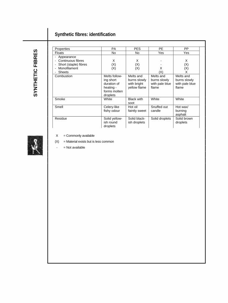
Synthetic fibres: identification
Properties PA PES PE PP Floats No No Yes Yes - Appearance - Continuous fibres - Short (staple) fibres - Monofilament - Sheets
X
(X) (X)
X
(X) (X)
- - X
(X)
X
(X) (X) X
Combustion Melts follow-ing short duration of heating -forms molten droplets
Melts and burns slowly with bright yellow flame
Melts and burns slowly with pale blue flame
Melts and burns slowly with pale blue flame
Smoke White Black with soot
White White
Smell Celery-like fishy odour
Hot oil faintly sweet
Snuffed out candle
Hot wax/ burning asphalt
SYN
THET
IC F
IBR
ES
Residue Solid yellow-ish round droplets
Solid black-ish droplets
Solid droplets Solid brown droplets
X = Commonly available (X) = Material exists but is less common - = Not available
Twine: number, tex, denier, metres/kg, diameter
■ Simple fibres Titre (denier) : Td = weight (g) of 9000 m of fibre Metric number : Nm = length (m) of 1 kg of fibre English number for cotton : Nec = length (in multiples of 840 yd) per lb International system: tex = weight (g) of 1000 m of fibre
■ Finished twine Runnage, metres/kg : m/kg = length (m) of 1 kg of finished twine Resultant tex : Rtex = weight (g) of 1000 m of finished twine ■ Equivalents and conversions
TWIN
Textile\system PA PP PE PES PVA Titre/denier 210 190 400 250 267
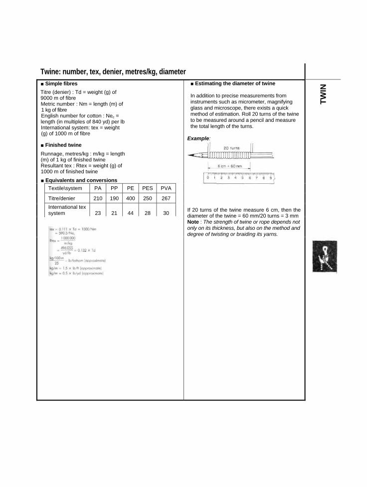
■ Estimating the diameter of twine In addition to precise measurements from instruments such as micrometer, magnifying glass and microscope, there exists a quick method of estimation. Roll 20 turns of the twine to be measured around a pencil and measure the total length of the turns.
Example:
International tex system 23 21 44 28 30
If 20 turns of the twine measure 6 cm, then the diameter of the twine = 60 mm/20 turns = 3 mm Note : The strength of twine or rope depends not only on its thickness, but also on the method and degree of twisting or braiding its yarns.
Twin : calculation of tex
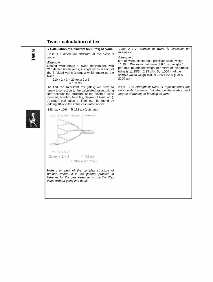
■ Calculation of Resultant tex (Rtex) of twine Case 1 : When the structure of the twine is known Example: Netting twine made of nylon (polyamide), with 210 denier single yarns, 2 single yarns in each of the 3 folded yarns (strands) which make up the twine.
210 x 2 x 3 = 23 tex x 2 x 3 = 138 tex
Case 2 : A sample of twine is available for evaluation Example ; 5 m of twine, placed on a precision scale, weigh 11.25 g. We know that twine of R 1 tex weighs 1 g per 1000 m, and the weight per metre of the sample twine is 11.25/5 = 2.25 g/m. So, 1000 m of the sample would weigh 1000 x 2.25 = 2250 g, or R 2250 tex
TWIN
To find the Resultant tex (Rtex) we have to apply a correction to the calculated value, taking into account the structure of the finished twine (twisted, braided, hard lay, degree of twist, etc.). A rough estimation of Rtex can be found by adding 10% to the value calculated above:
Note : The strength of twine or rope depends not only on its thickness, but also on the method and degree of twisting or braiding its yarns
138 tex + 10% = R 152 tex (estimate)
Note : in view of the complex structure of braided twines, it is the general practice in fisheries for the gear designer to use the Rtex value without going into detail.

Twine: equivalents of numbering systems
Eg.: twisted nylon (polyamide) twine m/kg Rtex
g/1000m yds/lb
a/ No of yarns denier
No. of deniers Td
Tex
20 000 13 500 10 000
50 75
100
9 9216 6964 960
210x234
420630840
47 70 93
6 450 4 250 3 150
155 235 317
3 199 2 1801 562
69
12
1 2601 8902 520
140 210 280
2 500 2 100 1 800
450 476 556
1 2401 041
893
151821
3 1503 7804 410
350 420 490
1 600 1 420 1 250
625 704 800
794704620
242730
5 0405 6706 300
559 629 699
1 150 1 060
980
870 943
1 020
570526486
333639
6 9307 5608 190
769 839 909
TWIN
910 850 790
1 099 1 176 1 266
451422392
424548
8 8209 450
10 080
979 1 049 1 119
630 530 400
1 587 1 887 2 500
313263198
607296
12 60015 12020 160
1 399 1 678 2 238
360 310 260
2 778 3 226 3 846
179154129
108120144
22 68025 20030 240
2 517 2 797 3 357
238 225 200
4 202 4 444 5 000
118112
99
156168192
32 76035 28040 320
3 636 3 916 4 476
180 155 130
5 556 6 452 7 692
897764
216240264
45 36050 40055 440
5 035 5 594 6 154
100 10 000 50 360 75 600 8 392
a/ yds/lb = approx. (m/kg)/2 Note: 210 denier = 23 Tex
m/kg = approx. (yds/lb) x 2

Twines: nylon (polyamide PA), multifilament twisted or braided
A = breaking load, dry without knots (single twine) B = breaking load, wet, knotted (single twine)
■ Twisted, continuous filament ■ Braided, continuous filament m/kg Rtex Diam.
mm A kgf
B kgf
m/kg Rtex Diam. Appox. mm
A kgf
B kgf
20 000 13 300 10 000
50 75
100
0.24 0.24 0.33
3.14.66.2
1.82.73.6
740645590
1 350 1 550 1 700
1.50 1.65 1.80
82 92 95
444952
6 400 4 350 3 230
155 230 310
0.40 0.50 0.60
91418
69
11
515410360
1 950 2 4502 800
1.95 2.30 2.47
110 138 154
607481
2 560 2 130 1 850
390 470 540
0.65 0.73 0.80
222630
141618
280250233
3 5504 0004 300
2.87 3.10 3.25
195 220 235
99 112117
TWIN
1 620 1 430 1 280
620 700 780
0.85 0.92 1.05
343943
212224
200167139
5 0006 0007 200
3.60 4.05 4.50
270 320 360
135155178
1 160 1 050
860 950
1.13 1.16
4751
2628
11510895
8 7009 30010 500
4.95 6.13 5.40
435 460 520
215225245
970 830 780
1 030 1 200 1 280
1.20 1.33 1.37
556467
293435
817157
12 300 14 000 17 500
5.74 5.93 6.08
600 680 840
275315390
700 640 590
1 430 1 570 1 690
1.40 1.43
1.5
758291
404347
500 385 315
2 000 2 600 3 180
1.61.92.0
110138165
567384
294 250 200
3 400 4 000 5 000
2.22.4
2.75
178210260
90104125
175 125
91
6 000 8 000 11 000
2.853.353.8
320420560
150190250

Twine, nylon (polyamide PA), monofilament and multimonofilament, Japanese numbering system
A = breaking load, dry without knots (single twine) B = breaking load, wet, knotted (single twine)
Diam. mm m/kg Tex* A kgf B
kgf 0.10 0.12 0.15
90 900 62 500 43 500
111623
0.650.91.3
0.4 0.55 0.75
0.18 0.20 0.25
33 300 22 700 17 200
304458
1.62.33.1
1.0 1.4 1.8
0.30 0.35 0.40
11 100 8 330 6 450
90120155
4.76.37.7
2.7 3.6 4.4
0.45 0.50 0.55
5 400 4 170 3 570
185240280
9.51214
5.5 6.5 7.5
0.60 0.70 0.80
3 030 2 080 1 670
330480600
172429
8.8 12.5
15 0.90 1.00 1.10
1 320 1 090
900
755920
1 110
364247
19 22 25
TWIN
1.20 1.30 1.40
760 650 560
1 3201 5401 790
556575
30 35 40
1.50 1.60 1.70
490 430 380
2 0602 3302 630
8698
110
46 52 58
1.80 1.90 2.00
340 300 270
2 9603 2903 640
120132145
65 72 75
2.50 180 5 630 220 113
Japanese numbering system for Monofilament ■ Multimonofilament
N' Japan Diam. (mm) N" Japan diam.
(mm) Diameter* x number of (mm) filaments m/kg A
Kgf 0.20 0.55 0.20 x 4 6 250 9 2 - 12 - 0.20 X 6 4 255 14 0.25 0.60 0.20 x 8 3 125 18 3 14 0.20 x 10 2 630 24 0.30 0.70 0.20 x 12 2 120 26 4 - 18 - 0.35 0.80 5 - 24 0.40 30 0.90 6 - 7 0.45 8 0.50
10 -
* for monofilament, tex and Rtex are the same.

Twine: polyester (PES), polyethylene (PE), polypropylene (PP) A = breaking load, dry without knots (single twine)
B = breaking load, wet, knotted (single twine) POLYESTER (PES) ■ twisted, continuous filaments
POLYPROPYLENE (PP) ■ twisted, continuous filaments
m/kg Rtex Diam. mm
A kgf*
B kgf m/kg Rtex
Diam. approx. mm
A kgf
B kgf
11 100 5 550 3 640
90 80
275
0.40 0.50
5.3 10.5
16
2.85
7.3
4 7603 4702 780
210 290 360
0.60 0.72 0.81
131519
89
11 2 700 2 180 1 800
370 460 555
0.60 0.70 0.75
212732
9.31214
2 3301 8201 560
430 550 640
0.90 1.02 1.10
252838
141519
1 500 1 330 1 200
670 750 830
0.80 0.85 0.90
374246
161820
1 090840690
920 119011
10
1.34 1.54 1.70
445871
233036
TWIN
1 080 1 020 900
925 980
1 110
0.95 1.00 1.05
505460
222426
520440350
1 920 2 290 2 820
1.95 2.12 2.32
92112132
475970
830 775 725
1 200 1 290 1 380
1.10 1.15 1.20
636873
282930
300210177
3 300 4 700 5 640
2.52 2.94 3.18
152190254
80100130
665 540 270
1 500 1 850 3 700
1.25 1.35 1.95
78 96
180
324078
POLYETHYLENE (PE) ■ twisted or braided thick filaments ■ twisted staple fibres
m/kg Rtex Diam. approx. mm
A kgf
B kgf m/kg Rtex
Diam. approx. mm
A kgf
B kgf
5 260 2 700 1 430
190 370 700
0.50 0.78 1.12
7..5 1027
5.57
19
4 7603 3302 560
210 300 390
0.60 0.73 0.85
91318
6 9
12 950 710 570
1 050 1 410 1 760
1.42 1.64 1.83
36 4960
243584
1 250 1 010 720
800 990
1 390
1.22 1.36 1.62
323857
222436
460 360 294
2 170 2 800 3 400
2.04 2.33 2.56
7593
116
546783
530420325
1 900 2 360 3 070
1.94 2.18 2.48
73 86
100
465459
225 190 130
4 440 5 300 7 680
2.92 3.19 3.68
135 170 218
97125160
240185150
4 100 5 400 6 660
2.90 3.38 3.82
150 215 300
88 120 170
100 10 100 3.96 290 210

Vegetable fibre ropes*
Tarred Cotton Hemp
Diameter mm
kg/100 m R kgf Standard Extra
3.0 1.056 45 Diametermm"
kg/ 100 m
R kgf
kg/ 100 m
R kgf
3.5 1.188 55 10 6.6 631 7.8 600 4.0 1.320 66 11 8.5 745 10.0 708 4.5 1.585 77 13 11.3 994 13.3 944 5.0 1.915 88 14 14.3 1 228 17.0 1 167 5.5 2.448 100 16 17.2 1 449 20.3 1 376 6.0 2.905 113 19 25.3 2017 29.8 1 916 6.5 3.300 127 21 30.0 2318 35.4 2 202
24 40.2 3 091 47.4 2 936 Sisal 29 59.0 4 250 70.0 4 037
Standard Extra 32 72.8 5 175 86.0 4916 Diameter
mm" kg /
100 m R kgf kg/
100 m R kgf 37 94.8 6 456 112.0 6 133
6 2.3 192 3.3 336 40 112.0 7 536 132.0 7 159 8 3.5 290 4.7 505 48 161.0 10 632 190.0 10 100
ROPE
10 6.4 487 6.4 619
11 8.4 598 9.0 924 Manilla 13 10.9 800 11.0 1 027 Standard Extra
14 12.5 915 14.0 1 285 Diameter
mm" kg/
100 m R kgf kg/
100 m R kgf
16 17.0 1 100 17.2 1 550 10 6.2 619 6.2 776 19 24.5 1630 25.3 2 230 11 9.15 924 9.25 1 159 21 28.1 1 760 29.30 2 390 13 11.2 1 027 12.4 1 470 24 38.3 2 720 39.5 3 425 14 14.2 1 285 15.0 1 795 29 54.5 3 370 56.0 4 640 16 17.5 1 550 18.5 2 125 32 68.0 4 0501 70.0 5510 19 25.5 2 230 26.65 2 970 37 90.0 5 220 92.0 7 480 21 29.7 2 520 30.5 3 330 40 24 40.5 3 425 41.6 4 780 48 29 58.4 4 800 59.9 6 380
32 72.0 5 670 74.0 7 450 37 95.3 7 670 98.0 9 770 40 112.5 8 600 115.8 11 120 48
R = Breaking strength, dry Safe working load, see page 5 " In English-speaking countries the size of a rope is sometimes measured by its circumference in inches (in.) or by its diameter in inches Diameter of rope 0 (mm) = approx. 8 x c (inch) Example: 0 (mm) of a rope of 2.25 inch circumference 0 (mm) = 2.25 x 8=18 mm (approximate)

Synthetic fibre rope*
Diameter
mm" Polyamide kg/100
(PA) R kgf
Polyethy ene kg/100m
(PE) Rkgf
Polyester kg/100m
(PES) R kgf
Polypropy ene Kg/100m
(PP) Rkgf
4 1.1 320 1.4 295 _ . 6 2.4 750 1.7 400 3 565 1.7 550 8 4.2 1 350 3 685 5.1 1 020 3 960
10 6.5 2 080 4.7 1 010 8.1 1 590 4.5 1 425 12 9.4 3 000 6.7 1 450 11.6 2 270 6.5 2 030 14 12.8 4 100 9.1 1 950 15.7 3 180 9 2 790 16 16.6 5 300 12 2 520 20.5 4 060 11.5 3 500 18 21 6 700 15 3 020 26 5 080 14.8 4 450 20 26 8 300 18.6 3 720 32 6 350 18 5 370 22 31.5 10 000 22.5 4 500 38.4 7 620 22 6 500 24 37.5 12 000 27 5 250 46 9 140 26 7 600 26 44 14 000 31.5 6 130 53.7 10 700 30.5 8 900 28 51 15 800 36.5 7 080 63 12 200 35.5 10 100 30 58.5 17 800 42 8 050 71.9 13 700 40.5 11 500 32 66.5 20 000 47.6 9 150 82 15 700 46 12 800 36 84 24 800 60 11 400 104 19 300 58.5 16 100 40 104 30 000 74.5 14 000 128 23 900 72 19 400
R = breaking strength, dry
ROPE
Direction of twist of twines, ropes and cables
' Safe working load see page 5 " Conversioninch-mm, seepage 15

Rope: joining knots and loops
Some knots are used more than others. In selecting which knot to use the following points should be considered : — the use of the knot — the type of rope — whether the knot will slip — whether the knot is permanent.
■ Joining two cords ■ Loops
ROPE

Knots for stoppers and mooring
Some knots are used more than others. In selecting which knot to use the following points should be considered : — the use of the knot — the type of rope — whether the knot will slip — whether the knot is permanent. ■ For stopping a rope from running through a narrow space (i.e. sheave)
ROPE
■ To close the codend of a trawl (codend knot)
■ To shorten a rope
■ Knots for mooring
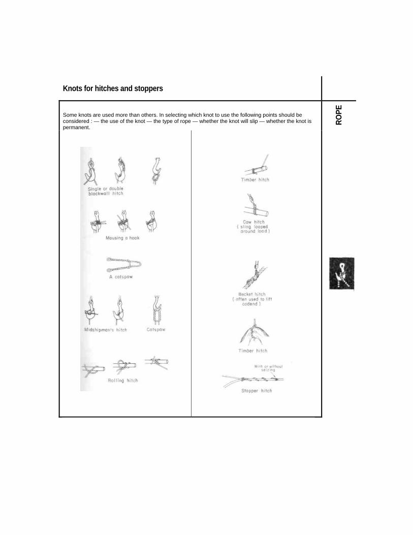
Knots for hitches and stoppers
Some knots are used more than others. In selecting which knot to use the following points should be considered : — the use of the knot — the type of rope — whether the knot will slip — whether the knot is permanent.
ROPE

Loss of breaking strength due to knots and splices
ROPE

Combination wire (1)*
■ Steel - Sisal 3 strands Untreated Tarred Diameter
(mm) kg/m Rkgf kg/m Rkgf 10 12 14
0.094 0.135 0.183
1 010 1 420 1 900
0.103 0.147 0.200
910 1 285 1 750
16 18 20
0.235 0.300 0.370
2 400 3 100 3 800
0.255 0.325 0.405
2 200 2 800 3 500
22 25 28
0.445 0.565 0.700
4 600 5 700 7 500
0.485 0.615 0.760
4 200 5 300 6 700
30 0.820 8 400 0.885 7 600
■ Steel - Sisal 4 strands
ROPE
Untreated Tarred Diameter (mm) kg/m Rkgf kg/m Rkgf
12 14 16
0.135 0.183 0.235
1 420 1 900 2 400
0.147 0.200 0.255
1 285 1 750 2 200
18 20 22
0.300 0.370 0.445
3 100 3 800 4 600
0.325 0.405 0.485
2 800 3 500 4 200
25 28 30
0.565 0.700 0.775
5 700 7 200 8 400
0.615 0.760 0.840
5 300 6 400 7 600
R = Breaking strength dry *Safe working loads, see page 5

22 Combination wire (2)*
■ Steel -Manilla B, 4 strands Untreated Tarred Diameter
(mm) kg/m Rkgf kg/m Rkgf 12 0.138 1 500 0.150 1 370 14 0.185 2 000 0.205 1 850 16 0.240 2 500 0.260 2 350 18 0.305 3 300 0.335 3 000 20 0.380 4 000 0.410 3 800 22 0.455 5 000 0.495 4 600 25 0.575 6 200 0.630 5 700 28 0.710 7 600 0.775 6 900 30 0.790 8 900 0.860 8 200 32 0.890 9 500 0.970 8 750 34 1.010 11 200 1.100 10 200 36 1.140 12 000 1.235 11 000 40 1.380 15 000 1.495 14000 45 1.706 18 500 1.860 17 500
50 2.045 22 500 2.220 20 000
ROPE
■ Steel - Polypropylene
Diameter (mm)
Number of strands
kg/m Rkgf
10 3 0.105 1 230 12 3 0.120 1 345 14 3 0.140 1 540 16 3 0.165 2 070 18 3 0.240 3 000 14 6 0.250 4 000 16 6 0.275 4 400 18 6 0.350 5 300 20 6 0.430 6 400 22 6 0.480 7 200 24 6 0.520 7 800 26 6 0.640 9 700
R = Breaking strength dry
* Safe working loads, see page 5

Floatlines and leadlines
Braided with a centre core of lead Diameter
(mm) kg/100 m Rkgf
2 2.5
2.3 - 3.5 4.6
73
3 3.5 4
6.5-7.1 9.1
11.1 -12.3
100
200
■ Floatline (with floats inside)
4.5 5
14.5 15.2-18.1 300
Principal advantages (1) and disadvantages (2)
1) Ease of rigging; less entanglement in the meshes.
Diameter (mm)
kg/100m Rkgf
7.2 8
7.5 12.5
360 360
8 9.5
18.8 21.3
360 360
9.5 9.5
23.8 27.5
360 360
ROPE
2) Need to calculate the rigging as a function of the distance between the floats; fragility of some types of float when passing through certain gillnet haulers.
11.1 12.7
30.0 37.5
360 675
Floatline (with floats inside)
Interval between floats (cm)
Flotation gf/100m Rope with a lead core in three strands
52 480 Diameter kg/100m Rkgf 47 500 6 8.7 495 35 570 7 11.2 675 20 840 8 13.3 865 35 2850 10 21.6 1 280
20 3 000
12 26.6 1 825 14 33.0 2510
■ Leadline (with leads inside)
Principal advantages (i) and disad-vantages (2)
1) Ease of rigging; uniform weight of leadline; better hanging; no entanglement in meshes.
2) In the case of breaking, loss of leads; difficult to repair; high cost.
R = breaking strength
there are also leadlines of 0.75; 0.90; 1.2; 1.5; 1.8 kg/100m

Steel wire rope: structure, diameter and use
Examples of common marine wire rope
Type Structure and diameter Example of Use S
7x7(6/1) central heart: steel
12 to 28 mm
Standing rigging +
6x7 (6/1) Central heart: textile
8 to 16 mm
Standing rigging Warps for small trawlers Small coastal vessels
+
6x12(12/fibre) Central heart, strand cores, fibre
8 to 16 mm
Bridles and warps for small trawlers moorings and running rigging ++
WIR
E RO
PE
6x19 (9/9/1) Central heart of steel or textile
16to30mm
Trawler warps +
6x19(12/6/1) Central heart of textile
8 to 30 mm
Trawler's sweeps and warps running rigging
+
6x24(15/9/fibre) Central heart and strand cores of textile
8 to 40 mm
Purse wire bridles and otter board strops, running rigging moorings and towing
++
6x37(18/12/6/1) Central heart of textile
20 to 72 mm
Purse wire moorings and running rigging mooring
++
S = flexibility + = poor or average ++ = good
As a general rule, the greater the number of strands, and the greater the number of filaments per strand, the greater the flexibility of the cable.

Galvanised steel wire rope: runnage. breaking strength* 25
(for structure, see page 24) examples 6x7 (6/1) 6x12 (12/fibre)
diam. mm
kg/ 100 m
R kgf
diam. mm
kg/ 100 m
R kgf
8 22.2 3 080 6 9.9 1 100 9 28.1 3 900 8 15.6 1 940
10 34.7 4 820 9 19.7 2 450 11 42.0 5 830 10 24.3 3 020 12 50.0 6 940 13 58.6 8 140 12 35.0 4 350 14 68.0 9 440 14 47.7 5 930 15 78.1 10 800 16 62.3 7 740 16 88.8 12 300
6x19(9/9/1) 6x19(12/6/1)
diam. mm
kg/ 100 m
R kgf
diam. mm
kg/ 100 m
R kgf
16 92.6 12 300 8 21.5 2 850 17 105 13 900 10 33.6 4 460 18 117 15 500 12 48.4 6 420 19 131 17 300
14 65.8 8 730
WIR
E RO
PE
20 145 19 200 16 86.0 11 400 21 160 21 200 18 109 14 400 22 175 23 200 23 191 25 400 20 134 17 800 24 208 27 600 22 163 21 600
24 193 25 700 25 226 30 000 26 245 32 400 6x 37 (18/12/6/1)
diam mm
kg/ 100 m
R kgf
6 x24(15/9/fibre) 20 134 17 100 Diam mm
kg/ 100 m
R kgf 22 163 20 700
8 19.8 2 600 24 193 24 600 10 30.9 4 060 12 44.5 5 850 26 227 28 900
14 60.6 7 960 R = Breaking strength 16 79.1 10 400 (steel 145 kgf/mm2) 18 100 13 200
* Safe Working Loads, see page 5 20 124 16 200 21 136 17 900 22 150 19 700 24 178 23 400 26 209 27 500
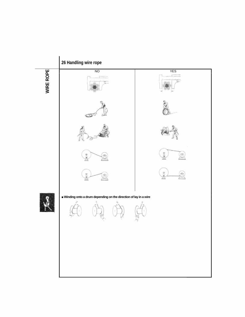
26 Handling wire rope
NO YES
WIR
E RO
PE
■ Winding onto a drum depending on the direction of lay in a wire

Matching wire ropes with drums and sheaves
the diameter of a drum (D) relative to the diameter of the wire rope (0) to be held on the drum —
■ Drums:
D/ depends on the structure of the wire rope, and depending on the particular situation, D should range from 20 to 48 . In practical use on board fishing vessels, depending on the space available, the following values are common :
D = 14 or more The diameter of a sheave (D) relative to the diameter of the wire rope (0) to be used with the sheave —
■ Sheaves :
D/ depends on the structure of the wire rope, and depending on the particular situation, D should range from 20 to 48 . In practical use on board fishing vessels, depending on the space available, the following values are common:
D = 9 or more
Width of sheave relative to the diameter of the wire rope
WIR
E RO
PE
■ Location of sheave relative to drum
Maximum fleet angle of a steel wire between a fixed sheave and a drum with manual or automatic spooling gear:
L - C x 5 (or more); C x 11 is recommended (In order to let a sheave shift with changing wire angles, it is often better to use a flexibly attached block rather than a fixed sheave.) ■ Cable clamps should be fastened with nuts on the standing part of the wire

Steel wire rope, small diameter
■ Stainless steel, heat treated and painted (examples) Construction diam.
mm R
kgf Construction diam. mm
R kgf
1.00 0.91 0.82 0.75 0.69 0.64 0.58
75 60 50 45 40 34 28
2.2 2.0 1.8 1.6 1.5 1.4 1.3
220 180 155 130 115 100
85
WIR
E RO
PE
1.5 1.4 1.3 1.3 1.2 1.1 1.0 0.9 0.8 0.7 0.6 0.6
210 170 155 140 120 100 90 75 65 50 40 30
2.4 2.2 2.0 1.8 1.6 1.5 1.4
290 245 200 175 155 130 110
2.2 2.0 1.8 1.6 1.5
290 245 200 175 155
1.9 1.8 1.6 1.5 1.3 1.2 1.1
290 245 200 175 155 135 110
■ Galvanised steel, not lubricated Number of Diameter
mm Strands Wires Diameter of
wires mm
kg/m Rkat (steel 80 - 90 kgf/mm )
2 5 1 plus 6 0.25 0.016 125 3 6 1 plus 6 0.30 0.028 215 4 6 1 plus 6 0.40 0.049 380 5 6 7 0.50 0.081 600 6 6 9 0.50 0.110 775
R = breaking stength

Meshes: Definition
■ Types of mesh nets ■ Dimension of mesh, stretched mesh (a), and mesh opening (OM)
Knotted netting
NET
WEB
BING
Knotted netting (Raschel type)
Hexagonal mesh
b = bar length
Meshes of metallic or plastic netting see page 107
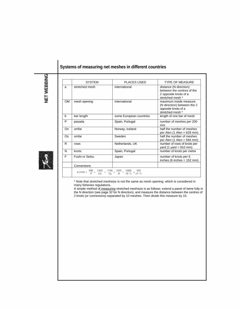
Systems of measuring net meshes in different countries
SYSTEM PLACES USED TYPE OF MEASURE
a stretched mesh international distance (N direction) between the centres of the 2 opposite knots of a stretched mesh *
OM mesh opening international maximum inside measure (N direction) between the 2 opposite knots of a stretched mesh *
b bar length some European countries length of one bar of mesh
P pasada Spain, Portugal number of meshes per 200 mm
On omfar Norway, Iceland half the number of meshes per Alen (1 Alen = 628 mm)
Os omfar Sweden half the number of meshes per Alen (1 Alen = 594 mm)
NET
WEB
BING
R rows Netherlands, UK number of rows of knots per yard (1 yard = 910 mm)
N knots Spain, Portugal number of knots per metre
F Fushi or Setsu Japan number of knots per 6 inches (6 inches = 152 mm)
Conversions
* Note that stretched meshsize is not the same as mesh opening, which is considered in many fisheries regulations.
A simple method of measuring stretched meshsize is as follows: extend a panel of twine fully in the N direction (see page 32 for N direction), and measure the distance between the centres of 2 knots (or connexions) separated by 10 meshes. Then divide this measure by 10.

Knots and edges or selvedges
■ Knots
NET
WEB
BING
Sheet bend
Double sheet bend
The height of the single knot is approximately equal to three times the diameter of the twine.
Reef knot
■ Edges and selvedges

Definition of cuts
NET
WEB
BING

Cutting rates
■ Cutting rate
D = number of meshes to decrease H = number of meshes in height
■ Values of the parts of a cut
Bars B
Sideknots N
Meshes T
1T2B 4N3B
NET
WEB
BING
Decrease in meshes D
0.5 0 1 1 +2x0.5 4x0 + 3x0.5
Height in meshes H
0.5 1 0 0 + 2x0.5 4x1 + 3x0.5
0.5 0.5
0 1
1 0
2 1 1.5/ 5.5=3/11

Common cutting rates and tapers
Number of meshes decreasing (or increasing) in width 1 2 3 4 5 6 7 8 9 10
1 AB 1T2B 1T1B 3T2B 2T1B 5T2B 3T1B 7T2B 4T1B 9T2B
2 1N2B AB 1T4B 1T2B 3T4B 1T1B 5T4B 3T2B 7T4B 2T1B
3 1N1B 1N4B AB 1T6B 1 T3B 1T2B 2T3B 5T6B 1T1B 7T6B
4 3N2B 1N2B 1N6B AB 1T8B 1T4B 3T8B 1T2B 5T8B 3T4B
5 2N1B 3N4B 1N3B 1N8B AB 1T10B 1T5B 3T10B 2T5B 1T2B
6 5N2B 1N1B 1N2B 1N4B 1N10B AB 1T12B 1T6B 1T4B 1T3B
7 3N1B 5N4B 2N3B 3N8B 1N5B 1N12B AB 1T14B 1T7B 3T14B
8 7N2B 3N2B 5N6B 1N2B 3N10B 1N6B 1N14B AB 1T16B 1T8B
9 4N1B 7N4B 1N1B 5N8B 2N5B 1N4B 1N7B 1N16B AB 1T18B
10 9N2B 2N1B 7N6B 3N4B 1N2B 1N3B 3N14B 1N8B 1N18B AB
11 5N1B 9N4B 4N3B 7N8B 3N5B 5N12B 2N7B 3N16B 1N9B 1N20B
NET
WEB
BING
12 11N2B 5N2B 3N2B 1MB 7N10B 1N2B 5N14B 1N4B 1N6B 1N10B
13 6N1B 11N4B 5N3B 9N8B 4N5B 7N12B 3N7B 5N16B 2N9B 3N20B
14 13N2B 3N1B 11N6B 5N4B 9N10B 2N3B 1N2B 3N8B 5N18B 1N5B
15 7MB 13N4B 2N1B 11N8B 1MB 3N4B 4N7B 7N16B 1N3B 1N4B
16 15N2B 7N2B 13N6B 3M2B 11N10B 5N6B 9N14B 1N2B 7N18B 3N10B
17 8N1B 15N4B 7N3B 13N8B 6N5B 11N12B 5N7B 9N16B 4N9B 7N20B
18 17N2B 4N1B 5N2B 7N4B 13N10B 1MB 11N14B 5N8B 1N2B 2N5B
Num
ber o
f mes
hes
in h
eigh
t (or
dep
th)
19 9N1B 17N4B 8N3B 15N8B 7N5B 13M12B 6N7B 11N16B 5N9B 9N20B
N = Sideknots T = Meshes B = Bars

Estimation of weight of netting
■ Knotless netting W = H x L x Rtex/1000 = H x L x (1000/m/kg)
■ Knotted netting W = H x L x Rtex/1000 x K = H x L x (1000/m/ka)
Where W = H x L x Rtex/1000 x K = H x L x (1000/m/ka)
W = estimated weight (g) of netting H = number of rows of knots in the height of the netting 2 x number of meshes L = Stretched length (m) of netting Rtex and m/kg = the size of twine in the netting K = knot correction factor to take into account the weight of the knots (single knot); see table below K = (knot correction factor) for different netting panels
Twine diameter (d) in mm Stretched meshsize (mm) 0.25 0.50 0.75 1.00 1.50 2.00 3.00 4.00
NET
WEB
BING
20 30 40
1.20 1.13 1.10
1.40 1.27 1.20
1.60 1.40 1.30
1.80 1.53 1.40
1.80 1.60
- 2.07 1.80
- - -
- - -
50 60 80
1.08 1.07 1.05
1.16 1.13 1.10
1.24 1.20 1.15
1.32 1.27 1.20
1.48 1.40 1.30
1.64 1.53 1.40
1.96 1.80 1.60
2.07 1.80
100 120 140
1.04 1.03 1.03
1.08 1.07 1.06
1.12 1.10 1.09
1.16 1.13 1.11
1.24 1.20 1.17
1.32 1.27 1.23
1.48 1.40 1.34
1.64 1.53 1.46
160 200 400
1.02 1.02
1.05 1.04 1.02
1.07 1.06 1.03
1.10 1.08 1.04
1.15 1.12 1.06
1.20 1.16 1.08
1.30 1.24 1.12
1.40 1.32 1.16
800 1 600
- -
- -
- -
1.02 -
1.03 -
1.04 1.02
1.06 1.03
1.08 1.04
Example : Knotted netting of twisted nylon twine, R1690 tex (590 m/kg), 100 mm bar length (200 mm stretched mesh length), height 50 meshes, length 100 meshes 50 meshes = 100 rows of knots in height Stretched length = 100 meshes x 0.200 m = 20 m Diameter of twisted polyamide twine 1690 Rtex = 1.5 mm (see page 12) K in the table above =1.12 (stretched mesh 200 mm; diameter 1.5 mm) W= 100 x 20 x (1690/1000) x 1.12 = 3785 g = about 3.8 kg

Calculating twine surface area
The drag of a net is proportional to the number and type of meshes in the netting, and to the orientation of the net panel(s) in the water.
NET
WEB
BING
where
S = twine surface area (square metres) N = number of meshes at the top of the panel n = number of meshes at the bottom of the panel H = number of meshes in the height of the panel a = stretched mesh (mm)
= diameter of twine (mm) Example : In the piece of netting shown above on the right, if N = 16; n = 6;
H = 6; a = 80 mm; 0 = 1.5 mm

Calculating twine surface area of a trawl
NET
WEB
BING
■ NET WEBBING: CALCULATING TWINE SURFACE AREA OF A TRAWL
PANEL Surface
No of Panels
H
A (mm)
(mm)
Twine Area
A 4 21 24 504 80 1.13 181 0.36 B 2 61 90 5490 80 1.13 181 1.99 C 1 279 30 8370 60 0.83 100 0.84 D 2 194 140 27160 60 0.83 100 5.43 E 2 136 100 13600 40 0.83 66 1.80 F 2 54 90 4860 80 1.13 181 1.76 G 2 97 30 2910 60 0.83 100 0.58 J 2 86 150 12900 40 1.13 90 2.32
Twine surface area without knots TOTAL S = 15.08 m2
In order to compare the twine surface areas of two trawls, the trawls should be as nearly the same shape as possible. In the case of such comparisons the surfaces of the lengthening pieces and the codend (parts without oblique orientation), will cause no significant drag, and can be disregarded.

Hanging ratios, definition and calculation ■ Hanging ratio (E) is commonly defined as : F = L / Lo = Length of rope on which a net panel is mounted (L) / Length of stretched netting
hung on the rope (Lo) Example: 200 meshes of 50 mm stretched mesh size hung on a rope of 8 m
■ Other expressions used for hanging ratio :
NET
WEB
BING
Estimate of the height as mounted % of stretched height
0.10 0.20 0.30
10% 20% 30%
10 5
3.33
90% 80% 70%
900% 400% 233%
99% 98% 95%
0.40 0.45 0.50
40% 45% 50%
2.5 2.22 2.00
60% 55% 50%
150% 122% 100%
92% 89% 87%
0.55 0.60 0.65
55% 60% 65%
1.82 1.66 1.54
45% 40% 35%
82% 67% 54%
84% 80% 76%
0.71 0.75 0.80
71% 75% 80%
1.41 1.33 1.25
29% 25% 20%
41% 33% 25%
71% 66% 60%
0.85 0.90 0.95
85% 90% 95%
1.18 1.11 1.05
15% 10% 5%
18% 11% 5%
53% 44% 31%
0.98 98% 1.02 2% 2% 20%
1) Also called external hanging co-efficient 2) Also called percentage of hanging in — Setting in x 100 — Looseness percentage of hanging — Hang in (Asia, Japan) 3) Also called Hang in ratio (Scandinavia)
Note : It is recommended that only the hanging ratio E be used
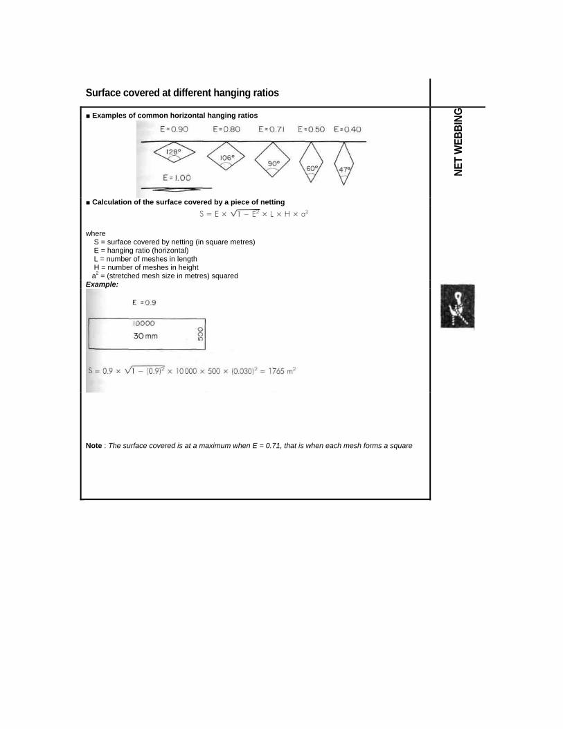
Surface covered at different hanging ratios
■ Examples of common horizontal hanging ratios
■ Calculation of the surface covered by a piece of netting
where S = surface covered by netting (in square metres) E = hanging ratio (horizontal) L = number of meshes in length H = number of meshes in height a2 = (stretched mesh size in metres) squared
NET
WEB
BING
Example:
Note : The surface covered is at a maximum when E = 0.71, that is when each mesh forms a square

Mounted height of a net
■ Calculation of mounted height The actual height of a mounted (rigged or hung) net depends on the stretched height and the hanging ratio. The general formula permitting estimation in all cases is :
mounted height (m) = stretched height (m) Where E2 = horizontal hanging ratio multiplied by itself Example: Given the piece of netting described on the preceding page with hanging ratio of 0.90 : Stretched height of netting
500 meshes of 30 mm, 500 x 30 = 15000 mm = 15 m Mounted height = stretched height x
NET
WEB
BING
■ Table for estimating mounted height
Example:
Given the piece of netting described on the preceding page, mounted with the horizontal hanging ratio 0.90, we can deduce from the table above (E to A to H) that its mounted height is 44% of the stretched height. Stretched height = 500 meshes of 30 mm = 500 x 30 mm = 15 m Mounted height = 44% of 15 m = 6.6 m

Joining panels of netting
■ Netting with straight edges (i.e. AB, AT, and AN)
Netting having the same number of meshes, and meshes of the same size, or approximately the same size.
Netting having a different number of meshes or meshes of a different size
Example of joining 2/3
2 meshes of 45 mm on 3 meshes of 30 mm
(2 x 45 = 3 x 30)
NET
WEB
BING
■ Netting cut obliquely with a combination of cuts B and N orT Pieces having a different number of meshes and different cuts

Mounting (hanging or rigging) panels of netting
Examples NE
T W
EBBI
NG

Terms for describing fish hooks
FISH
HOO
KS
■ - Examples of fish hook characteristics
Regular hooks Forged hooks Number gap (mm) Shank diam.
(mm) Number gap (mm) Shank diam.
(mm)
12 11 10
9.5 10 11
1 1 1
2 1 1/0
10 11 12
1 1 1
9 8 7
12.5 14 15
1.5 1.5 2
2/0 3/0 4/0
13 14.5 16.5
1.5 1.5 2
6 5 4
16 18 20
2 2.5 3
5/0 6/0 8/0
10 27 29
2.5 3 3.5
3 2 1
23 26.5 31
3 3.5 4
10/0 12/0 14/0
31 39 50
4 5 6
1/0 35 4.5

Principal types of fish hooks ■ Straight hooks ■ Reversed hooks ■ Specialised hooks for particular
species or fishing methods 'J' shape, ring eye
Circle hook
Reversed, flatted shank
Large gap
Trolling
Double hook, tuna Trolling
FISH
HOO
KS
Shank bent down
Flatted shank
With swivel
■ Double and treble hooks
Double, reversed
Double, closed
Treble, straight
Longlines
Flatted shank, hole in flat,
for tuna or shark
Pole and line
Tuna jig hook, barbless
Barbless, for tuna poles and line
■ Kirbed (offset) hooks
Kirbed, ring eye
Treble, reversed

Lures, knots for fish hooks
■ Lures
FISH
HOO
KS
■ Knots for ring-eyed hooks
■ Knots for flatted shank hooks

Swivels, snaps, knots for longlines
■ Swivels
LINE
FIS
HING
ACC
ESSO
RIES
■ Snaps
■ Knots for joining branchline or snood to mainline
■ Knots for joining branchline to snood

Floats for seines: examples
Examples : in expanded PVC, two types of manufacture
L Ø Ø Wt. (g) in air
buoyancy kgf
195 150 28 350 2.2 203 152 28 412 2.2 203 175 28 515 3.0
L Ø Ø Wt. (g) in air
buoyancy kgf
192 146 26 326 2.4 198 151 28 322 2.5 198 174 33 490 3.5
FLOA
TS
For the dimensions given, the buoyancy varies depending on the material.
Rough estimation of the buoyancy may be found by measuring the float.
Estimation of the number of floats necessary for a seine :
There are a great variety of seine floats, with L ranging from 100 to 400 mm; 0 from 75 to 300 mm; and buoyancy from 300 to 22 000 gf.
Durability is a most important char-acteristic of a seine float.

Floats for gillnets and seines (1)
Examples Dimensions (mm)
Ø x L Ø Buoyancy
(gf)
30 x 50 50 x 30 50 x 40
6 8 8
30 50 67
65 x 20 65 x 40 70 x 20
8 8
12
55 110 63
70 x 30 80 X 20 80 x 30
12 12 12
95 88
131 80 x 40 80 x 75 85 x 140
12 12 12
175 330 720
100 x 40 100 x 50 100 x 75
14 14 14
275 355 530
100 x 90 100 x 100 125 x 100
14 14 19
614 690
1 060
150 x 100 25 1 523
FLOA
TS
Estimating the buoyancy from the size of the
Float: buoyancy (in gf) = 0.67 x L (cm) x Ø 2 (cm)2
Dimensions (mm)
Ø x L Ø
Buoyancy (gf)
76 x 44 88 x 51
8 8
70 100
101 x 57 140 x 89
10 16
160 560
Dimensions (mm)
Ø x L Ø Buoyancy
(gf) 76 x 45 89 x 51 102 x 57
8 8
10
70 100 160
140 x 89 158 x 46
16 8
560 180
Estimation of the buoyancy from the size of a float
buoyancy (in gf) = 0.5 x L (cm) x Ø 2 (cm)2 Ø2 = external diameter multiplied by itself

Floats for gillnets and seines (2)
Examples L
(mm) Ø
(mm) Ø
(mm) Buoyancy
(gf) 25 32 6 20 32 58 10 60 42 75 12 110 58 66 12 175
FLOA
TS
60 70 12 200
65 75 12 220
65 80 12 250
58 23 8
60 25 10
72 35 25
80 40 35
100 50 100
Ø (mm)
Ø (mm)
Buoyancy (gf)
146 100 110 146 88 200 146 82 240 184 120 310 184 106 450 200 116 590
200 112 550

Spherical floats and trawl floats
Examples from suppliers' catalogues Diameter
(mm) Volume (litres)
Buoyancy kgf
Maximum depth (m)
plastic, 200 4 2.9 1 500 center hole 200 4 3.5 350 280 11 8.5 600 plastic, 75 0.2 0.1 400 side hole 100 0.5 0.3 500 125 1 0.8 400-500 160 2 1.4 400-500 200 4 3.6 400-500
FLOA
TS
plastic, with "ears" 203 4.4 2.8 1 800 or lugs plastic 200 4 3.5 400 with screw 280 11-11.5 9 500-600 lug Aluminium 152 1.8 1.3 1 190. 191 3.6 2.7 820 203 4.4 2.8 1 000 254 8.6 6.4 1 000
The table below shows that, for floats of equal diameter (200 mm in this case), the volume and
buoyancy may vary a great deal, depending on the material and placement of holes or lugs.
Ø 200 mm Plastic,
center hole Plastic,
side hole Plastic, with screw lug
Aluminium, with lugs
Volume 4 4 4 4 4.4 Buoyancy (kgf) 2.9 3.5 3.6 3.5 2.8 * Note: The maximum effective depth of a float depends on the manufacture, and should be
specified by the supplier. It cannot be deduced from the appearance, shape or colour

Floats (buoys) for marking nets, lines and traps
Ø
(mm) L
(mm) Ø
(mm) B
(mm) C
(mm) Buoyancy
kgf
125 300 25 200 90 2.9 150 530 25 380 100 7.8 150 600 25 450 100 9.2 150 680 25 530 100 10.4 150 760 25 580 100 11.5 200 430 45 290 110 10.5
FLOA
TS
L (mm)
L (mm)
H (mm)
Ø (mm)
Buoyancy kgf
300 180
300 180
200 180
35 25
12 – 15 4
Ø (mm)
Ø (mm)
Ø (mm)
L (mm)
L (mm)
Buoyancy kgf
510 160 11 185 18 2 760 240 30 350 43 8
1 015 320 30 440 43 17 1 270 405 30 585 43 34 1 525 480 30 670 43 60 1 905 610 30 785 48 110 2 540 810 30 1 000 48 310
Ø (mm)
Ø (mm)
Ø (mm) L (mm) Buoyancy kgf
760 240 38 340 7.5 1 015 320 38 400 17 1 270 405 51 520 33.5
1 525 480 51 570 59

Groundrope leads and rings
Examples
■ Leads for ropes
L(mm) 25 38 38 32 32 32 25 45 45 45
Ø (mm) 16 16 13 10 8 6 6 5 5 6
G (g) 113 90 64 56 50 41 28 28 28 16
■ Leads for lines, examples of shapes
■ Example of mould for leads
■ Example of groundrope rings for a gillnet
Ex: Ø mm Ø mm Pg 210 5 105
220 6 128

Chains and thimbles*
Ø mm
Approximate Weight kg/m
Ø mm
Approximate weight kg/m
5 0.5 11 2.70 6 0.75 13 3.80 7 1.00 14 4.40 8 1.35 16 5.80 9 1.90 18 7.30
■ Chains
10 2.25 20 9.00
HAR
DWAR
E
High tensile steel Ø
mm LxE
(mm) S.W.L. Ton.f Breaking strength Ton.F
Weight kg/m
7 21 X 10.5 1.232 6.158 1.090 10 40x15 2.514 12.570 2.207 13 52x19.5 4.250 21.240 3.720 16 64x24 6.435 32.175 5.640
19 76 X 28.5 9.000 45.370 7.140 ■ Thimbles
■ Clips for wire rope
Cable clamps or 'bulldog grips'
Safe Working Load see page 5

Steel accessories for joining : shackles, links and clips*
Ø
(mm) C
(mm) O
(mm) S.W.L Ton.f
B.S. Ton.f
6 8
10
12 16 20
18 24 30
0.220 0.375 0.565
1.3502.2503.400
12 14 16
24 28 32
36 42 48
0.750 1.200 1.830
4.5007.25011.000
18 20 24
36 40 40
54 65 75
2.200 2.600 3.600
13.20016.00022.000
30 45 100 5.830 35.000
HAR
DWAR
E
■ Links and Clips
* Safe Working Load see page 5

Swivels
Ø (mm)
E (mm)
Ø (mm)
S.W.L.* Ton.f
B.S.** Ton.f
8 17 14 0.320 1.920 10 25 15 0.500 3.000 12 28 18 0.800 4.800 14 35 20 1.100 6.600 16 35 20 1.600 9.600 18 38 25 2.000 12.000 20 43 26 2.500 15.000
HAR
DWAR
E
25 50 33 4.000 24.000
■ Swivel, forged steel
30 60 40 6.000 36.000 ■ Swivel, tempered steel and hot galvanized
Ø mm
S.W.L.* Ton.f
Weight Kg
8 0.570 0.17 16 2.360 1.12 22 4.540 2.61 32 8.170 7.14
■ Swivel, high tensile stainless steel
A (mm)
B (mm)
C (mm)
S.W.L.* Ton.f
B.S.** Ton.f
Weight Kg
146 48 20 3 15 1.3 174 55 27 5 25 2.1
200 62 34 6 30 2.8

Hooks and 'G' links*
HAR
DWAR
E
"G" link High tensile steel
F
mm S.W.L.* Ton.f
B.S.* Ton.f
25 30 34 38
1.1 3.6 5.0 7.0
8 15 25 35
* Safe working load and breaking strength see page 5

Spreaders, codend release and purse rings
■ For trawl
■ For seine : Opening purse clips or rings
HAR
DWAR
E
Interior Diam, mm A
Exterior Width mm B
Exterior Length mm C
Thickness Mm
D
Opening Mm
E
Breaking strength
Ton.t
Weight kg
86 128 180 22 34 0.400 1.3 107 172 244 32 47 3.800 4.0 107 187 262 32 52 5.400 5.0 110 187 262 37 53 6.500 6.0 75 128 200 19 40 1.800 2.0 94 150 231 25 47 2.200 3.0
103 169 253 28 50 3.000 4.0 103 169 262 35 53 3.500 5.0 106 175 264 38 53 3.600 6.0 25 65 111 17 17 5.000 0.5 38 80 140 15 25 6.000 0.65 36 90 153 19 29 12.000 1.1

Elements of trawl groundropes: steel bobbins
Ø mm
L mm
A Weight in air Kg
B Weight in air
kg
200 165 7.5 9.5 250 215 10 12.5 300 260 18 22 350 310 29 34 400 360 35 40
Ø
mm L
mm Ø
mm A
Weight in air kg
B Weight in air kg
200 380 30 12 14
HAR
DWAR
E
250 570 32 15 17.5 300 610 35 25 29 350 660 60 42 46 400 715 60 51 56
Example of rigging a groundrope with bobbins (1), chains (2} and spacers (3)

Elements of trawl groundropes: steel bobbins
Examples ■ Bunts Ø (mm) 229 305 356 406
Wt. in air (kg) per piece 4.40 9.10 11.80 19.50
Wt. in water (kg) per piece 0.98 2.10 2.85 4.4
■ Bobbins Ø (mm) 305 356 406
Wt. in air (kg) per piece
5.10 8.00 11.50
Wt. in water (kg) per piece 1.65 2.20 3.50
HAR
DWAR
E
■ Spacers L(mm) 178 178 Ø (mm) 121 165 Ø (mm) 44 66
Wt. in air (kg) per piece 1.63 2.30 Wt. in water (kg)
per piece 0.36 0.57
■ Rings or "cookies" (made from old tyres) diameter ext. Ø (mm) 60 80 110 diameter int. Ø (mm) 25 30 30
Weight* (kg/m) 2.3 3.0 7.5
diameter ext. Ø (mm) diameter int. Ø (mm)
200 45
240 45
280 45
Weight* per piece (kg) 5.0 7.0 10.5
* Weight in air

Slings and tackles LI
FTIN
G