dentascan in oral imaging - units.it
TRANSCRIPT

Clinical Radiology (2001) 56: 700±713doi:10.1053/crad.2001.0785, available online at http://www.idealibrary.com on
Pictorial Review
DentaScan in Oral Imaging
K. M. AU-YEUNG, A. T. AHUJA, A. S. C. CHING, C. METREWELI
Department of Diagnostic Radiology and Organ Imaging, Prince of Wales Hospital, The Chinese University of HongKong, Shatin, N.T., Hong Kong
Received: 14 July 2000 Revised: 17 January 2001 Accepted: 9 April 2001
In the past, dental disease and lesions involving the jaw were either evaluated by plain radiography ortomography. The advent of spiral computed tomography (CT) and DentaScan is changing the imagingtrend. It is now not only used for pre-implant assessment but also in the diagnosis of lesions a�ecting thejaw. This pictorial review discusses the role of DentaScan in the various abnormalities that may a�ectthe mandible and maxilla. Au-Yeung, K. M. et al. (2001). Clinical Radiology 56, 700±713.
# 2001 The Royal College of Radiologists
Key words: DentaScan, oral pathology/computed tomography.
DentaScan is a computed tomography (CT) softwareprogram that allows the mandible and maxilla to be imagedin three planes: axial, panoramic and cross-sectional. It hasbeen widely used pre-operatively for implant surgery as itprovides a comprehensive assessment of the morphologyand measurement of the dental implant. Introduced in themid-1980s, DentaScan o�ered improvements in the evalu-ation of the osseous mandible and maxilla and has beenreported to be useful in head and neck surgery [1±3]. Wehave explored the clinical usefulness of DentaScan invarious oral lesions, other than mandibular implants.
IMAGING TECHNIQUES
All patients in this study were imaged using helical CT(High Speed Advantage, General Electric Medical System,Milwaukee, WI, U.S.A.). Since the DentaScan programdoes not permit angulation of the gantry, it is essential thatthe patient is properly positioned so that true axial imagesare obtained. During CT, the patient should remainmotionless. If both the mandible and maxilla are beingevaluated, a separate run should be performed for eachbecause the axial plane of the mandible is di�erent fromthat of the maxilla. From the preliminary lateral scout view,the upper and lower limits of the study and the scan planeparallel to the alveolar ridge for either maxilla or mandible
should be de®ned. Axial CT with 1 mm contiguous slices isperformed using a bone algorithm, dynamic mode, 15A cm®eld of view, 512 � 512 matrix, 140 kV and 70 mA. Thedata is transferred to the workstation for post-processing.The actual data acquisition time for maxilla or mandible
is about 15 min. From the workstation and using the axialscan data, a curved line along the midportion of thealveolus is created on an axial image of the mandible ormaxilla. The axial image chosen should be at the level of theroots of the teeth and demonstrate the full contour of themandible and maxilla [4]. The curved line de®nes the planeand location of the reformatted panoramic images. It alsomarks the beginning and the end of the cross-sectionalimages. The program, which is provided by General Electric(GE, Milwaukee, WI, U.S.A.), then automatically refor-mats the images.When the reconstruction is complete, three sets of images
are displayed: axial, cross-sectional, and panoramic. Typi-cally there are approximately 30±50 axial images, 40±100cross-sectional images, and ®ve panoramic images. It shouldbe noted that each CT view can be related to the other by aseries of scale marks that appear on the ®lms. Marks, whichrun along the side of the cross-sectional and panoramicimages, correspond to the direct axial slices that are used toreformat the images. Marks along the bottom of thepanoramic images correspond to numbered cross-sectionalimages. A millimeter scale displayed on the bottom of thecross-sectional ®lms is used to verify the degree ofmagni®cation and to obtain accurate measurements.The e�ective dose of the standard DentaScan Protocol is
around 8.16 mSv. The DentaScan is not free from artefact,
0009-9260/01/090700+14 $35.00/0 # 2001 The Royal College of Radiologists
Author for correspondence and guarantor of study: Dr K. M. Au-Yeung, Department of Diagnostic Radiology, Queen Mary Hospital,102 Pokfulam Road, Hong Kong. Fax: 852 2855 5497; E-mail:[email protected]

PICTORIAL REVIEW 701
Fig. 1 ± Mandibular erosion by a retromolar trigone squamous cell carcinoma (SCC). In a DentaScan series of (a) panoramic and (b) cross-sectionalviews, the mandible is edentulous with bony destruction of the angle of right mandible and soft tissue thickening in the panoramic and cross-sectionalview. The mandibular canal is preserved but the mandibular foramen is destroyed as seen in the cross-sectional view. Biopsy con®rmed the presence ofretromolar invasive SCC with bony erosion.

702 CLINICAL RADIOLOGY
particularly that due to motion. Some patients may haveamalgam ®llings in their teeth. Since the ®llings are abovethe jaw bone, the artefact casted by amalgam would beminimal and not a�ect the quality of images. Similarly,root-canal procedures and bridgework above the jaw bonehave a minimal e�ect on image quality.
PATHOLOGY
Squamous Cell Carcinoma of the Oral Cavity
Only 7% of oral cavity lesions are malignant and SCCaccounts for 90% of the tumours [5]. Most masses within
the oral cavity, both benign and malignant, are amenable todirect clinical examination. The primary purpose ofimaging is to detect deep or submucosal extent and adjacentosseous involvement. Bony erosion is better characterizedby multi-planar CT (Fig. 1).
Unlike standard pantomography, there is no super-imposition of other osseous structures in DentaScan.The image quality is sharp and clear, providingbetter tissue contrast resolution. Anatomic structures suchas the inferior alveolar canal, mental foramen, mandi-bular foramen, buccal and lingual cortical margins, and thewall of the maxillary sinus can be clearly identi®ed andevaluated. It is essential to evaluate the mandible in
Fig. 2 ± Oral SCC with mandibular erosion. Pre-operative DentaScan (a) and (b) contiguous cross-sectional views show subtle focal cortical thinningin the upper lingual aspect of the left mandible (arrow b). The tooth is intact. The site is adjacent to the oral SCC. At surgery, the corresponding bonycortex was found to be eroded by the tumour.

PICTORIAL REVIEW 703
Fig. 3 ± Ameloblastoma. The DentaScan (a) panoramic and (b) cross-sectional views show a well-de®ned, expansile, osteolytic lesion in the mentalregion of the mandible. The overlying cortex is thin. The root of the incisor and canine have been cut sharply by the lesion, which erodes the left distalmandibular canal and mental foramen (arrow a). Biopsy con®rmed the diagnosis of ameloblastoma.

704 CLINICAL RADIOLOGY
Fig. 4 ± Ameloblastoma within a dentigerous cyst. The (a) panoramicand (b) cross-sectional views of the DentaScan show a well-de®nedunilocular cystic lesion in the angle of right mandible. Uneruptedmolar tooth is present in the cystic lesion. The rest of the teeth aredisplaced by the cystic lesion. The appearances are suggestive of adentigerous cyst. Surgical excision of cyst was performed which revealsthe presence of ameloblastoma inside the cyst. The ®nal pathologicaldiagnosis was a unicystic ameloblastoma, probably arising from adentigerous cyst.

PICTORIAL REVIEW 705
these cases as it a�ects patient management. Radiotherapycan be used if there is no bone involvement, whereasinvolvement of the mandible (19±26% of oral cavitycarcinomas) [6±8] usually requires mandibular resection.On cross-sectional views in DentaScan, buccal and lingualcortical involvement is clearly identi®ed (Fig. 2). Theseviews provide the surgeon with better pre-operative
information in relation to the extent of resection andpatient counselling.
Ameloblastoma
Ameloblastoma accounts for about 1% of all tumoursand cysts of the jaws. The mandible is involved in about
Fig. 5 ± Osteogenic sarcoma. DentaScan (a) panoramic and (b) cross-sectional views show ill-de®ned sclerosis of the left mandible extending to thesymphysis menti. The cross-sectional view also demonstrates the multifocal hypodensities in the sclerotic mandibular medulla. No cortical break orperiosteal thickening was noted. Interestingly, the periodontal space of the left premolar and molar are slightly widened with ¯oating toothappearance (arrow, a). Biopsy con®rmed osteogenic sarcoma.

706 CLINICAL RADIOLOGY
80% and the maxilla in 20%. The distal ascendingramus and molar regions are most commonly a�ected.Although pantomography was often used for assessmentof this tumour in the past, DentaScan now provides a betterevaluation of the lesion. Features suggestive of anameloblastoma are a well-circumscribed, expansile, low
attenuation lesion with cortical resorption (Fig. 3). Thetumour may be unilocular (Fig. 4) or multi-locular. Aunilocular ameloblastoma usually occurs in youngerpatients (usually between 20 and 30 years) and is locatedin the mandibular molar region (Fig. 4) whereas themultilocular tumour a�ects patients between 3rd and 7th
Fig. 6 ± Cementoblastoma. DentaScan (a) panoramic and (b) cross-sectional views show a well-de®ned expansile, ground-glass lesion witha radiolucent halo in the left body of the mandible. The panoramicview shows the loss of the left second premolar and left ®rst molarteeth. The cross-sectional views depict the relation of the teeth with theground-glass lesion. The lingual bony cortex is lost and probably dueto pressure-erosion by the lesion. The lesion appears benign inappearance and found pathologically to be a benign cementoblastoma.

PICTORIAL REVIEW 707
decade of life [9], and involves the mandible and maxillawith equal frequency.
Osteogenic Sarcoma
Osteogenic sarcoma is the most common malignanttumour of the mandible. It is less aggressive than osteogenicsarcoma of the long bones. Mortality is often due to localpersistence or intracranial extension. Osteogenic sarcoma ofthe facial bones occurs most often in patients between 30and 39 years. The radiographic [10] and CT ®ndings arevariable and non-speci®c. Some indicate an aggressiveneoplastic process and some may show the presence of a
mineralized osteoid or chondroid matrix associated withbone destruction, periosteal reaction, and a soft-tissuemass. Other features include the `¯oating tooth' resultingfrom resorption of bone around a root (Fig. 5).
Mandibular Cementoblastoma
Cementoblastoma is a rare benign neoplasm of functionalcementoblasts, which is characterized by the formation of acementum or cementum-like mass connected with a toothroot. The teeth commonly a�ected are in the pre-molar±molar region of the jaws, and the lesion may disrupt thetooth innervation by surrounding the root apex. As a result,
Fig. 7 ± Dentigerous cyst. DentaScan (a) panoramic and (b) cross-sectional views shows the impacted third molar tooth at the angle of rightmandible, which is encircled by an sharply marginated, expansile cyst. Features are of a dentigerous cyst.

708 CLINICAL RADIOLOGY
many of the involved teeth are not viable [11]. The lesionoccurs most frequently in men under 25 years of age. Thetumour is commonly solitary and the mandibular ®rstmolar is the most frequently involved region. On plainradiography and pantomogram, the lesion is well de®ned,with central radiopaque material, is attached to the toothroot and a surrounding radiolucent zone of uniform width,which represents the peripheral unmineralized tissue. Wecould ®nd no previous report of the appearance of acementoblastoma on a DentaScan. The DentaScan ®ndingswere similar to those on plain radiography (Fig. 6).
Surgically, the lesion is easily enucleated since it is benignand is surrounded by a capsule.
Dentigerous Cyst
A dentigerous cyst is the second most common odonto-genic cyst, occurring most often in the mandibular thirdmolar or maxillary cuspid regions. The cysts result from thecystic degeneration of the enamel organ after partial or totaldevelopment of the crown [9]. Plain ®lms demonstrate anexpansile radiolucent lesion associated with a crown or
Fig. 8 ± Mandibular osteomyelitis. In the angle of right mandible, the contiguous cross-sectional view (a) and (b) of the DentaScan show multi-focalill-de®ned `moth-eaten' hypodensities against a sclerotic background. Periosteal thickening is visualized in the buccal and lingual aspect of themandible. There is also an empty socket of the second molar due to dental infection. DentaScan suggests mandibular osteomyelitis arising from thedental infection. Biopsy con®rmed the presence of acute and chronic in¯ammation with Gram-positive rods.
PICTORIAL REVIEW 709
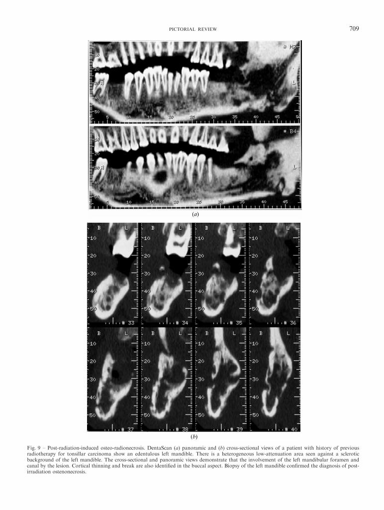
Fig. 9 ± Post-radiation-induced osteo-radionecrosis. DentaScan (a) panoramic and (b) cross-sectional views of a patient with history of previousradiotherapy for tonsillar carcinoma show an edentulous left mandible. There is a heterogeneous low-attenuation area seen against a scleroticbackground of the left mandible. The cross-sectional and panoramic views demonstrate that the involvement of the left mandibular foramen andcanal by the lesion. Cortical thinning and break are also identi®ed in the buccal aspect. Biopsy of the left mandible con®rmed the diagnosis of post-irradiation ostenonecrosis.

710 CLINICAL RADIOLOGY
unerupted tooth. Cortical expansion is usually present atdiagnosis. Because of its multiplanar capability, theselesions are better demonstrated and evaluated by aDentaScan (Fig. 7).
Chronic Infection
Chronic osteomyelitis, a persistent infection of bone, hastwo forms: chronic sclerosing osteomyelitis and chronicsuppurative osteomyelitis. Abscess formation, subtle peri-osteal reaction, and sequestration of the non-viable bonedue to suppurative osteomyelitis are well demonstrated byDentaScan (Fig. 8).
Post-operative or Post-Radiotherapy Assessment
SCC of the oral cavity may be treated by eithersurgical resection or radiotherapy. In clinical practice thepresence of tumour recurrence or radiation-inducednecrosis is a common dilemma and a biopsy is indicatedto make a de®nitive diagnosis. However, complete assess-ment of the jaw lesion (change in density, cortical breakor presence of soft tissue component) is useful forevaluating recurrence. DentaScan provides this informa-tion in di�erent planes, and also shows the presence ofthe soft tissue component (Fig. 9). Surgical treatmentconsists of mandibulectomy and bone grafting.DentScan demonstrates the alignment of the graft in
Fig. 10 ± Graft evaluation. A 57-year-old patient with gingival carcinoma with left hemimandibulectomy and iliac crest microvascular bone graftperformed. The post-operative DentaScan (a) panoramic and (b) cross-sectional views show the alignment of the graft in cross-sectional, panoramicand axial views. The depth of the metallic nail and the anatomotic sites can be evaluated.

PICTORIAL REVIEW 711
multiple planes, which is crucial for surgical assessment(Fig. 10).
Trauma
Because of its multi-planar capability, DentaScan isextremely useful in the evaluation of trauma. Properassessment of the site, extent and orientation of the fractureis possible before surgery (Fig. 11).
Congenital Hyperplasia of the Condyle
Developmental bilateral mandibular hyperplasia is anuncommon anomaly. Asymmetry of the mandible is afrequent clinical presentation. The most prominent facialfeatures include a shift of the chin to the short side andprominence of the mandibular angle on the long side. Inmany cases, the cause of mandibular asymmetry leading to
facial deformity is unclear on physical examination andimaging assessment is warranted [12,13]. Imaging isperformed to exclude other causes (such as trauma) andfor treatment planning. Although pantomography andmagnetic resonance imaging (MRI) have been used fordepicting the condyles, the panoramic view on DentaScanprovides better evaluation of the bony process (Fig. 12).
Phakomatoses
Neuro®bromatosis type 1 (NF1), or von Recklinghausendisease, is the most common form of phakomatosis. Phako-matoses are genetic disorders with abnormal neuroectoder-mal and mesenchymal proliferation leading to neoplastic orhamartomatous lesions in the central and peripheralnervous systems, as well as in the skin. Osseous craniofacialabnormalities occur rarely compared to the axial orperipheral skeletal manifestations. The spectrum of imaging
Fig. 11 ± Trauma. The (a) panoramic and (b) cross-sectional views on a DentaScan identify a well de®ned linear lucency cut with separation offragment involving the root of left canine, left premolar and left molar teeth. The fracture extends to the coronoid process of the left mandibleresulting in the displacement of fragments. The left mandibular foramen and canal are intact.

712 CLINICAL RADIOLOGY
features is wide, including calvarial defects, dysplasticsphenoid, changes in the sella turcica and orbit, mandibularchanges and enlargement of neural foramina [14,15].Imaging plays a major role in screening, follow-up
and treatment of the patients with NF1. DentaScanprovides essential information in patients who requirecraniofacial plastic surgery, in particular those casesrequiring jaw reconstruction. Panoramic views provide abetter pro®le of bony abnormalites ranging from aslender coronoid process, an obtuse mandibular angle,hypoplasia of the body or ramus to enlarged mandibular,or mental foramina secondary to inferior alveolar nerveinvolvement. Multiple cross-sectional images of the mand-ible can reveal unerupted or malpositioned teeth associatedwith a cystic cavity [15,16] and provide detailed dentalmeasurements (Fig. 13).
CONCLUSION
As CT is widely available, DentaScan can play a widerrole in evaluating lesions of the mandible and maxilla. Itprovides valuable information in the assessment of oral
cavity tumours (pre-and post-operative, post-radiother-apy); lesions of the jaw (benign and malignant, infection)and bony anatomy before and after implant surgery.
REFERENCES
1 Yanagisawa K, Abrahams JJ, Friedman CD. DentaScan: a newimaging method for the maxilla and mandible. Presented at theNew England Otolaryngological Society, Boston, MA, October1990.
2 Vining E, Friedman CD, Abrahams JJ, Lowlicht R. Diagnosis oforoantral ®stula using DentaScan. Poster presentation at theAmerican Academy of Otolaryngology ± Head and Neck Surgery,San Diego, CA, September 1990.
3 Abrahams JJ, Levine B. Expanded applications of DentaScan(multiplanar computerized tomography of the mandible andmaxilla). Int J Periodont Rest Dent 1990;10:465±471.
4 Abrahams JJ. Dental implants and multiplanar imaging of the jaw.In: Som P, Curtin H, eds. Head and Neck Imaging, 3rd edn.St Louis, MO: Mosby-Year Book Inc, 1996, 350±374.
5 Yarington CT. Pathology of the oral cavity. In: Paparella MM,Shumrick M, eds. Otolaryngology. Philadelphia: W. B. Saunders,1980.
6 Marchetta FC, Sako K, Murphy JB. The periosteum of themandible and intraoral carcinoma. Am J Surg 1971;122:711±713.
Fig. 12 ± Prominent condylar head. The cross-sectional view of the DentaScan of 18-year-old man shows the prominence of the condylar head. Nomarginal osteophytes or joint erosion is seen. Bone scintigraphic examination revealed the condylar head had twice the tracer uptake compared to theadjacent cranium.

PICTORIAL REVIEW 713
7 Close LG, Merkel M, Burns DK, Schaefer SD. Computedtomography in the assessment of mandibular invasion by intraoralcarcinoma. Ann Otol Rhinol Laryngol 1986;95:383±388.
8 Gilbert S, Tzadik A, Leonard G. Mandibular involvement by oralsquamous cell carcinoma. Laryngoscope 1986;96:96±101.
9 Del Balso AM. RSNA Special Course in Head and Neck Imaging.Radiological Society of North America Inc., 1996, 23±31.
10 Waldron C. Bone pathology. In: Neville BW, Damm DD,Allen CM, Bouquout JE, eds. Oral and Maxillofacial Pathology.Philadelphia: W. B. Saunders, 1995, 443±492.
11 Mehlisch DR, Dhalin DC, Masson JK. Ameloblastoma: aclincopathologic report. J Oral Surg 1972;30:9±22.
12 Markey RJ, Potter BE, Mo�ett BC. Condylar trauma and facialasymmetry: an experimental study. J Maxillofac Surg 1980;8:38±51.
13 Wang-Norderud R, Ragab RR. Unilateral condylar hyperplasiaand the associated deformity of facial asymmetry. Scand J PlastReconstr Surg Hand Surg 1977;11:91±96.
14 Chapman S, Nakielny R. Aids to Radiological Di�erentialDiagnosis, 3rd edn. London: W. B. Saunders, 1995, 565±567.
15 Gupta SK, Nema HV, Bhatia PL, Sasibabu K, Kesharwani R. Theradiological features of craniofacial neuro®bromatosis. Clin Radiol1979;30:553±557.
16 Kaplan I, Calderon S, Ka�e I. Radiological ®ndings in the jaw andskull of neuro®bromatosis type 1 patients. DentomaxillofacialRadiol 1994;23:216±220.
Fig. 13 ± Phakomatoses. Dentascan (a) panoramic (b) cross-sectionalviews in a patient with NF1. Panoramic views show marked hemi-hypoplasia of the left mandible. There was associated dislocation of thetemporomandibular joint and malocclusion (not shown on theseimages). Thinning and remodelling of the condylar process andcoronoid process associated with a `wide mouth' notch are noted. Themandibular angle is obtuse and a rudimentary bony protuberance isnoted (small arrow). Note the enlarged mandibular foramen (longarrow), unerupted left third molar and impacted right third molar. Theenlargement of the inferior alvelolar canal is better seen on cross-sectional images.