department of administrative services bim · phases. the project website will be used by the...
TRANSCRIPT

BIM GUIDELINESJOSH GEBALLE Commissioner
CONSTRUCTION SERVICES
450 Columbus BoulevardHartford, CT 06103
DEPARTMENT OF ADMINISTRATIVE SERVICES
CT DAS 0420 (Rev. 11.09.15)

Page 1 of 8
11.09.2015 0420 – DAS BIM Guidelines
DAS BIM Guidelines
BUILDING INFORMATION MODELING (BIM) LIST OF DESIGN, PRECONSTRUCTION AND CONSTRUCTION SERVICES
SOFTWARE
A. The project shall be designed and implemented using Building Information Modeling (BIM) authoring software and all subsidiary models as may be necessary for design, analysis, fabrication and construction. All subsidiary models must be interoperable and support robust exchange with the BIM authoring software.
MODELING GOALS
A. Throughout the design and construction phases, BIM will be utilized to develop a parametric model, derived data, and the coordinated discipline models for the project.
1. Throughout the pre−construction phases, the Architect’s (sometimes referredto as the “Designer”) project design software and discipline specific tools will beutilized to develop and model the design of the project, to tag materialcomponents, systems and/or assemblies, generate schedule and derived data,create data bases, perform required analysis, clash avoidance, and develop 2−Dand 3−D presentations and reviews. During construction, the Architect willdevelop, model and incorporate relevant approved change order sketches(SK’s). Prior to achieving Final Completion of construction the Architect willincorporate all recorded (Record Drawings – as designed) conditions into themodel. The final model must be purged of all views not associated with projectsheets. (NOTE: Approved shop drawings and submittals will not be included intothe model).
2. During the pre−construc on phases on a CM at Risk project, the ConstructionManager (CM) may use the Architect’s model to generate quantity takeoffs forestimating purposes, develop periodic clash reports and facilitate clashresolution reviews. During construction, the CM will provide virtual schedulingwith updates, and utilize the upgraded models during coordination meetings toinform tradesmen of affected phases of construction. The model shall be used in thefield to support reviews, site logistics, and ongoing construction.
3. On some renovation projects, Building Information Model authoring softwareand processes may be inappropriate for the design and construction phases ofthe project. Such a case may be a very limited renovation project or a roofingreplacement. In such instances, the Architect/ Engineer (A/E) team will advisethe Department of Administrative Services of the possible reason(s) whyutilizing BIM may be inappropriate. The Department Chief Architect, inconjunction with the Department Project Manager will make the final

DAS BIM Guidelines Page 2 of 8
24 December, 2015 0420 – DAS BIM Guidelines
determination regarding the use of BIM before the A/E contract is implemented.
GENERAL REQUIREMENTS
A. A description of how the modeling goals will be met (i.e., a BIM Execution Plan (BIMxP)) is required by the Architect and, subsequently, by the Construction Manager (CM).
B. Department will provide a template of its standard BIM Execution Plan Outline (see appendix A) to the Architect to create the “Architect’s BIM Execution Plan”. The Architect’s BIMxP shall identify how the Architect and the engineering disciplines (i.e., the design team) will develop, be responsible for, and incorporate their information into the coordination model, and provide decision support and model reviews. The BIM model will be developed, managed and coordinated by the Architect. The Architect’s BIMxP will identify their proposed in−house or outsourcing plan, and all software programs that will be used to satisfy the design modeling goals, analysis, decision support and reviews. The BIMxP must be consistent with the format and principles of the BIM Execution Plan Outline (the “BIMxP Outline”). In addition, the BIMxP will include a Model Content Matrix (Appendix B) that will be completed by the design team in conjunction with the CM or GC. The BIM Guidelines complement The Consultants Procedure Manual, the A/E’s Contract with the Department and the Owner−CM Agreements. The BlMxP Outline and Model Content Matrix are incorporated herein by reference and copies are available on the DAS / Division of Construction Services website. In the event of any conflict between the BIMxP Outline these BIM Guidelines or the contract between the Department and the A/E, Construction Manager , then the provisions of these DAS BIM Guidelines and the respective contract will take precedence as it relates to the development and use of BIM.
1. For CM at Risk projects, it is recognized that the Construction Manager (CM) may be named before the Architect has completed the Design Intent Model. The primary activity of the CM in this situation will be the provision of pre−construc on services per the CM’s contract. It is expected the CM will be proficient in Building Information Modeling technology. Where such services may impact the development of the Building Information Model, the Architect will collaborate with the CM to insure the BIM reflects the input of the CM. Furthermore, the CM will advise the Architect in matters where the expertise of the CM can complement and/or supplement that of the Architect.
C. When multiple users and project models are anticipated a project working point shall be established and documented in the BIMxP. The project working point shall be placed on a separate workset and easily identifiable in both plan and elevation. All

DAS BIM Guidelines Page 3 of 8
24 December, 2015 0420 – DAS BIM Guidelines
models that are to be linked together shall use the same project working point
D. All model deliverables shall be saved and delivered in their native format (i.e.,.rvt for Revit, .pln for ArchiCAD, etc.) and in IFC format, .dwg and .dwf format, .nwd, .nwf, .nwc as required and distributed to project team members.
E. The project team will have access to the current model throughout the design, pre− construction and construction phases. “Project team” is defined as: Architect, Engineering Consultants to the Architect, relevant third parties, the Department and CM.
COORDINATION AND CLASH DETECTION
A. A team approach is required for the BIM process. The model will be used with different parties for different tasks. For example, as part of the integration and virtual coordination scope of work, the Architect will make design files available to the CM who will integrate all 3D content into the appropriate clash detection program (such as Navisworks) to satisfy the CM modeling goals. The Architect and CM will work collaboratively to resolve all detected clashes and develop an end product model that represents a fully workable, constructible project; with phasing projected and linked to the virtual schedule (where required by the BIMxP). If early packages are bid, it is understood that the model may not be fully developed for those work elements (i.e., substructure, superstructure and under−slab utilities); however, the end product model must be complete and approved by the Department
B. Project Manager prior to receiving final bids.
1. Physical conflicts exceeding the specified tolerance of 0.5 inch (to be adjusted in consultation with the project design team and the Department) will be documented and provided to the Architect for review.
2. All adjustments to resolve conflicts, as determined by the design team, will be incorporated in the 3D model before a new integration and clash detection iteration is performed.
3. Attendance at specific coordination meetings with the design team, the CM and the Department, is required (virtual collaboration may be permitted by the Department Project Manager). These milestones will be identified in the BIMxP. At the discretion of the Department Project Manager, collaboration tools such as Autodesk 360 may be used.
4. The Architect, and the CM, GC or DB team, as appropriate, will be responsible to update the Department Project Manager on the status of the model coordination, analysis, virtual scheduling and quantity takeoffs as a standard agenda item at all project meeting.
COMMUNICATION AND MANAGEMENT
A. The Architect and the CM , as appropriate, shall each appoint a “BIM Manager”. The BIM Manager(s) will be responsible for receiving modeling information from their related team and enduring the model information is correct, being communicated, updated and incorporated into a master building information model. Each party is

DAS BIM Guidelines Page 4 of 8
24 December, 2015 0420 – DAS BIM Guidelines
responsible for maintaining any individual design or analysis models and providing their modeling information, at appropriate intervals.
1. An FTP or project website or other appropriate collaboration/communications tools will be provided by the Architect throughout the design and construction phases. The project website will be used by the project team. The FTP or project website will be password protected and is required to be accessible for only one project.
2. During the design phase, the Architect will be the primary BIM Manager/Coordinator and will have primary responsibility for data management and standards. The architect will coordinate with the BIM activities of the CM .
3. During construction, the CMwill be the primary BIM Manager/Coordinator. The CM/GC will coordinate with the Architect to ensure the design model is maintained and updated for the purposes of coordination and record model/drawings or other purposes as outlined in the BIMxP
4. Uniformat and Omniclass for model element identification and classification is to be used. Adherence to appropriate Department CAD standards, functional space naming, and room numbering will be documented in the BIMxP. COBie data documentation may be a required project goal. It is the responsibility of the Architect or the DB team to identify the User‐Agency’s data requirements, if any, while developing the BIMxP
MODEL ELEMENTS (“The Model”)
The determination of specific elements to be modeled and the Level of Development is intended to be a collaborative process led by the Architect incorporating the Project Goals, Owner Deliverables and other requirements and will be recorded as part of the BIMxP and Model Element Matrix. For reference, please visit www.BIMforum.org/LOD for the most current Level of Development Specification produced by the BIM forum.
A. Site/Civil Elements
1. Existing Conditions Modeling
a. Existing site grading surface modeling of the entire property. The surface model shall extend 50' beyond the property line in all directions to provide site context to the information model.
b. Existing manhole locations shall be modeled with appropriate depth and size of existing structures. Pipe inverts and pipe sizes should be modeled and extended 10' minimum in direction of pipe location from the existing manholes.
c. Elements to include in the basic site plan model are:
i. Surface model contours

DAS BIM Guidelines Page 5 of 8
24 December, 2015 0420 – DAS BIM Guidelines
ii. Architectural massing model of surrounding buildings iii. Driveways iv. Parking areas v. Walkways vi. Landscaping beds vii. Trees viii. Utility Poles ix. Other Street Furniture x. Major underground utilities (primary electrical feed, water mains,
sewer connection, etc.)
2. Proposed Site Modeling
a. Proposed site grading surface model should extend to the property line.
b. Proposed manholes and piping elevations should be modeled with sloping or horizontal gradients as designed.
c. All underground piping should be modeled to within 10' of the proposed building footprint.
d. All proposed vehicular paving and pedestrian walkway paths should be modeled with appropriate slopes and elevations.
B. Architectural Elements
1. The architectural model is to include, without limitation, partition walls, ceilings, chases, door and window openings, exterior envelope, roof, stairs and railings.
a. Interior partitions at correct thickness and height.
i. Tag types (ratings, masonry, drywall, shaft wall, glass block, etc.)
b. MEP chases (vertical)
c. Elevator shafts
d. Stairwells
e. Finish floor at correct elevation and thickness
f. Ceilings at correct elevation and thickness
i. Tag types (ratings, drywall, acoustical, etc.)
g. Exterior envelope at correct thickness with proposed exterior material facing to the outside
i. Tag material types (masonry, curtain wall, metal panel, rain screen, etc.)

DAS BIM Guidelines Page 6 of 8
24 December, 2015 0420 – DAS BIM Guidelines
h. Interior and exterior door sizes, locations, and ratings
i. Reflected ceiling plans of all levels with recessed light locations modeled with approximate dimensions and elevations of lighting fixtures, speakers, etc.
j. Furniture layouts corresponding to the Furnishings and Equipment (F&E) requirements of the client agencies.
i. Furniture and equipment simulations to be similar in dimensions to actual proposed (use manufacturers models if available and to the extent they are consistent with the LOD set forth in the BIMxP).
k. All interior storage units, cabinetry, racks, shelving, etc.
C. Structural Elements
1. Structural modeling will include, but not be limited to, all substructure elements (i.e., spread footings, piles, foundations, grade beams, etc.), all superstructure elements (i.e., beams, columns, girders, framing and bracing sans connection details, shear elements, bearing walls, etc.), structural floor and roof decks, elevator shafts and stairwells. When necessary, the structural modeling will be developed first to correspond to an early bid package.
2. All openings greater than one square foot in area. Including floors, roofs and walls.
D. Mechanical, Electrical, Plumbing and Fire Protection (MEPFP) Elements
1. MEPFP modeling will include, but not be limited to, all horizontal and vertical solid and flexible duct runs, modeled at correct sizes, slopes and shapes. All mechanical equipment elements should be designed and modeled based on largest case manufacturers equipment (i.e., RTU's, VAV boxes, boilers, generators, chillers, etc.), in order to assure adequate physical space to accommodate “worst case” scenarios. Equipment clearances for access, service space requirements, gauge readings, access plates, valve clearance and other operational clearances are to be modeled.
a. Mechanical / sheet metal
i. Ducts (including insulation) ii. Air handling equipment iii. Boilers iv. Pumps v. Associated piping – 1 ½” and larger (piping to be modeled to its
outside diameter, including insulation). vi. Supply and return louvers, grilles and diffusers
b. Plumbing
i. Piping 1 ½” and larger (piping to be modeled to its outside

DAS BIM Guidelines Page 7 of 8
24 December, 2015 0420 – DAS BIM Guidelines
diameter, including insulation) ii. Risers iii. Pitched drains (i.e., roof drain mains, etc.) iv. Pumps and equipment v. Fixtures will be located with penetration stub into walls, floors
and ceilings vi. Sleeved objects will be located in all exterior penetrations to the
correct outside diameter
c. Fire Protection
i. Piping – 2” and larger in concealed areas, 1” and larger for exposed.
ii. Valves – including fire department connections and test headers. iii. Equipment including fire pumps and controllers. iv. Sprinkler heads aligned with the reflected ceiling plans v. Risers – Isometric diagrams vi. Sleeve locations for all exterior walls vii. Sprinkler zone plans indicating the areas served and the type of
system provided.
d. Electrical
i. Conduit – 1 ½” and larger ii. All major equipment iii. Switchgear iv. Transformers v. Panel boards vi. Generators vii. Conduit viii. Locate and model all lighting fixtures as the overall required
embed volume d.
e. Fire Protection
i. Equipment (i.e., fire pumps, hose racks, standpipes, etc.) ii. Risers iii. All piping
f. AV/IT and Security may be required per the BIMxP
4D CONSTRUCTION PHASING MODEL
A. General Information Modeling Requirements
1. The CM shall review the coordinated design model at various stages of design for constructability, costing and scheduling purposes.
2. The Architect shall incorporate reasonable changes requested by the CM. If the

DAS BIM Guidelines Page 8 of 8
24 December, 2015 0420 – DAS BIM Guidelines
CM plans to construct the project in phases for scheduling purposes, the CM will inform the Architect of planned construction phasing and the CM will update the model accordingly.
B. Preparation of the 4D Construction Phasing Model
1. The CM shall integrate its approved, electronic CPM schedule with the coordinated design model using a program such as Navisworks. This will occur at approximately 50% DDs (with emphasis on early package elements), 50% CDs, and 100% CDs, or more frequently if required by the Department Project Manager. At completion of CDs a two−week minimum time period will be used to provide a final clash detection review and report with work points, accommodate any last minute changes or modifications by the Architect, and allow the Architect to correct any clashes prior to soliciting final package bids. The intent is to provide bidders with bid documents based on a coordinated model that can be constructed within the scheduled timeframe barring unforeseen conditions and/or Owner−initiated changes.
2. The CM is responsible for model object/ schedule activity resolution and correlation. The CM will provide the Architect with any revised phasing logic information so appropriate model edits that may be required can be accommodated.
3. The CM will use “Task Types” and “Appearance Definitions” within Navisworks (or approved equal) to communicate the following:
a. (trades by color)
b. (critical path by color)
c. (other as necessary)
4. The CM, GC, or DB team shall use Navisworks or other approved scheduling software to communicate design intent, means and methods (where possible) and sequencing of work to subcontractors in pre−bid meetings.
5. Updated or “status” 4D schedules will be prepared for monthly construction coordination meetings. There is the need to have 4D Virtual Construction Model meetings (beginning of each month), chaired by the CM, GC, or DB team, at which all subcontractors field supervisors whose tradesmen will work that month will need to address the projected following month of work. In the event that one or more subcontractors may prepare 3D models for their own execution of work the CM shall review for acceptability and, if deemed acceptable and consistent with the CM's control of the work and the Department Project Manager, the CM, shall incorporate this 3D content into the coordinated design (Navisworks, or equal) model.

AppendixA
Sample BIM Execution Plan Outline BIM Goals What are the project specific goals for the use of BIM
Specific Project Challenges Owner Requirements
Model Managers Contact information for Project Team Planned Models An outline of what models are expected at each phase of the project Model Platform and Software A description of what software and file formats will be used for each discipline/purpose during the project Model Development Specification Means to describe the expected model content, by discipline and phase including expected uses. This would include a description of the content that goes beyond a simple LOD number. The following documents can be utilized to describe the model content and expected uses:
AIA‐E203 Building Information Modeling and Data Exhibit Model Content Matrix (Appendix B)
Owner Deliverable Requirements What is to be delivered at the end and any other points in the project? Clash Detection and Coordination Outline the general expectations
Model color schemes for model objects (colors by discipline) Expected Collision Tests and Tolerances
Model Sharing and Handoff A description of how, when and under what terms models will be shared with both internal and external project team members including:
Collaboration Platform Model exchange schedule License template for external sharing
If model management will change during the course of the project describe how, when and under what terms that will happen Milestones Outline team expectations for BIM specific meetings and checkpoints to inform and update the BIM Execution Plan. The following are recommended:
Project Kickoff Design Phases Construction Manager Onboarding Construction Startup Sub‐Contractor Engagement Closeout

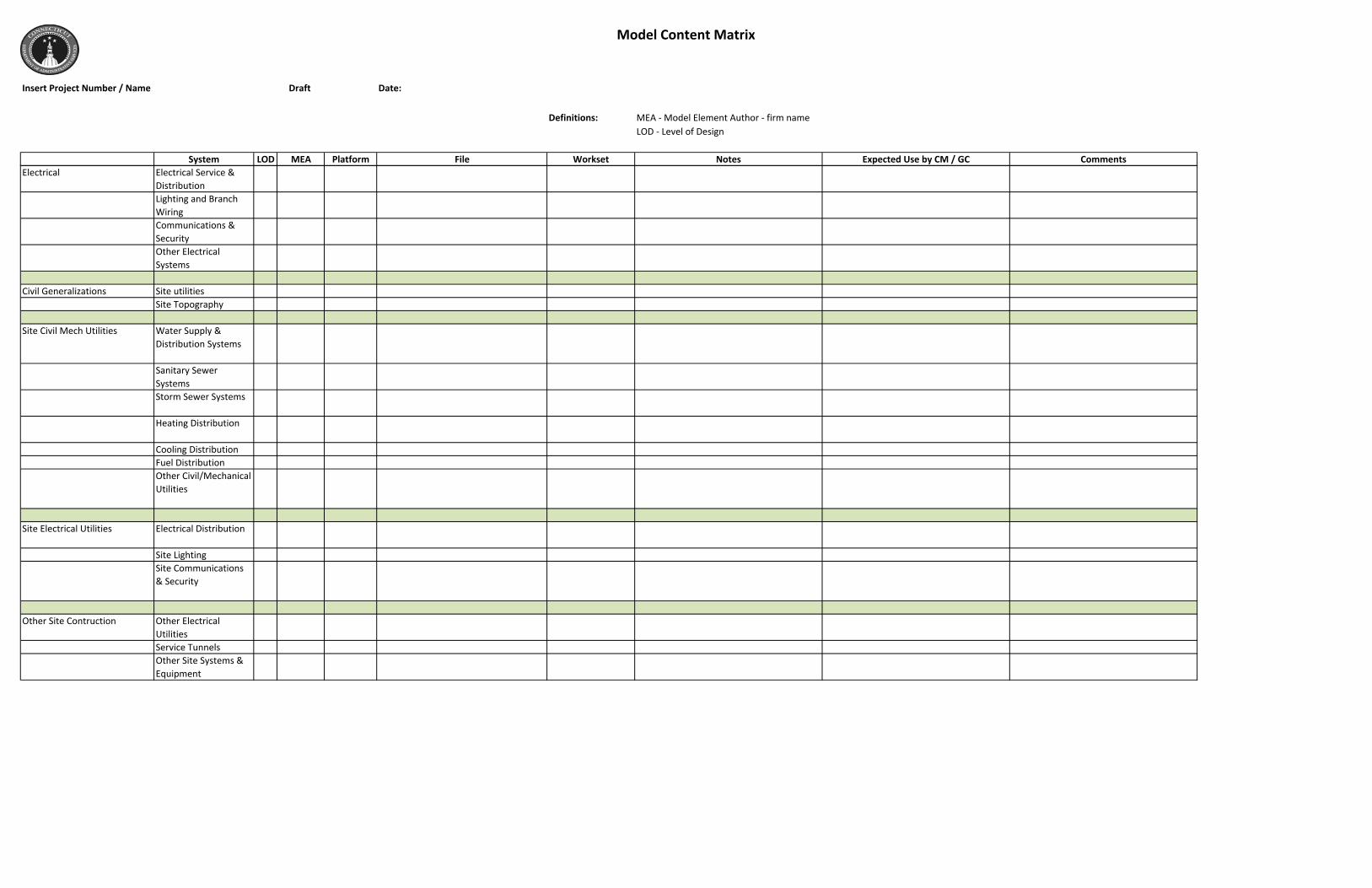
Model Content Matrix
Insert Project Number / Name Draft Date:
Definitions: MEA ‐ Model Element Author ‐ firm nameLOD ‐ Level of Design
System LOD MEA Platform File Workset Notes Expected Use by CM / GC Comments
Substructure Foundations 200 STR Revit 2014 XXX_XX_STR_S12_Central.rvt Structual Framing Cast in place concrete modeled to correct size and location including masonry shelf.
Information in these rows provided for sample purposes
Slab on Grade 200 STR Revit 2014 XXX_XX_STR_S12_Central.rvt Structual Framing Modeled to approximate size more definition required, major slab steps to be modeled, Minor depressions are not likely to be modeled.
Slab steps and depressions are important to CMR for coordination of underslab utilities
Information in these rows provided for sample purposes
Floor Construction 200 STR Revit 2014 XXX_XX_STR_S12_Central.rvt Structual Floors Elevated slabs modeled to approximate size and compositionStructural steel modeled with correct beam and column sizes, locations and orientation. Kickers are not modeled nor are gusset plates at bracing
Kicker locations are important to CMR Information in these rows provided for sample purposes
200 ARCH Revit 2014 XXX_XX_Shell_A12_Central.rvt Building Shell Architectural Edge of Slab Model, this will reflect the design intent of the edge of slab including openings greater than 12"
Information in these rows provided for sample purposes
Roof Construction 200 STR Revit 2014 XXX_XX_STR_S12_Central.rvt Structual Framing Elevated slabs modeled to approximate size and compositionStructural steel modeled with correct beam and column sizes, locations and orientation
Information in these rows provided for sample purposes
Exterior Exterior Walls 200 ARCH Revit 2014 XXX_XX_Shell_A12_Central.rvt Building Shell Modeled to approximate length,width and location. Exterior wall may reflect a clash with structural slabs and foundations
Information in these rows provided for sample purposes
Exterior Windows 200 ARCH Revit 2014 XXX_XX_Shell_A12_Central.rvt Building Shell Individual and ganged windows modeled to correct size and orientation, Tagged and TypedWindow wall systems generically modeled indicating approximate, opening size and location as well as mullion layout, all joint conditions require reference details
Information in these rows provided for sample purposes
Exterior Doors 200 ARCH Revit 2014 XXX_XX_Shell_A12_Central.rvt Building Shell Modeled to correct size and orientationTagged and Typed
Information in these rows provided for sample purposes
Roof Coverings 200 ARCH Revit 2014 XXX_XX_Shell_A12_Central.rvt Building Shell Sloped or Horizontal surfaces to approximate, width and length, not including, overlap, vertical parapet covering or other joint conditions
Information in these rows provided for sample purposes
Roof Openings 200 ARCH Revit 2014 XXX_XX_Shell_A12_Central.rvt Building Shell Modeled to approximate length,width and location for openings larger than 12"
Information in these rows provided for sample purposes
Interiors Interior PartitionsInterior GlazingInterior Doors

Model Content Matrix
Insert Project Number / Name Draft Date:
Definitions: MEA ‐ Model Element Author ‐ firm nameLOD ‐ Level of Design
System LOD MEA Platform File Workset Notes Expected Use by CM / GC CommentsStair ConstructionStair FinishesWall FinishesFloor FinishesCeiling FinishesElevators
Equipment and Furnishings Equipment
Building Sitework Landscaping
MEP Generalizations HVAC DuctworkHydronic Piping PlumbingElectrical
Plumbing Plumbing FixturesDomestic Water DistributionSanitary WasteRain Water Drainage
Other Plumbing Systems
HVAC Energy SupplyHeat Generating SystemsCooling Generating SystemsDistribution Systems
Terminal & Package UnitsControls & InstrumentationSystems Testing & BalancingOther HVAC Systems & Equipment
Fire Protection SprinklersStandpipesFire Protection SpecialtiesOther Fire Protection Systems
Model Content Matrix
Insert Project Number / Name Draft Date:
Definitions: MEA ‐ Model Element Author ‐ firm nameLOD ‐ Level of Design
System LOD MEA Platform File Workset Notes Expected Use by CM / GC CommentsElectrical Electrical Service &
DistributionLighting and Branch WiringCommunications & SecurityOther Electrical Systems
Civil Generalizations Site utilitiesSite Topography
Site Civil Mech Utilities Water Supply & Distribution Systems
Sanitary Sewer SystemsStorm Sewer Systems
Heating Distribution
Cooling DistributionFuel DistributionOther Civil/Mechanical Utilities
Site Electrical Utilities Electrical Distribution
Site LightingSite Communications & Security
Other Site Contruction Other Electrical UtilitiesService TunnelsOther Site Systems & Equipment