department of defense handbook guidance for …
TRANSCRIPT

MIL-HDBK-527 13 April 2017
DEPARTMENT OF DEFENSE HANDBOOK
GUIDANCE FOR INTERMITTENT FAULT EMULATOR (IFE)
This handbook is for guidance only. Do not cite this document as a requirement.
AMSC N/A FSC 6625
NOT MEASUREMENT SENSITIVE
Downloaded from http://www.everyspec.com

MIL-HDBK-527
ii
FOREWORD 1. This handbook is approved for use by all Departments and Agencies of the Department of Defense (DoD).
2. This handbook provides guidance on use and application of the Copernicus Technology Ltd. part number CTL990495 Intermittent Fault Emulator (IFE). This handbook does not assume prior knowledge of the IFE. It is recommended that both beginner and advanced users read the entire user manual for both the intermittent fault diagnostic equipment and IFE before starting any diagnostic equipment evaluation. The IFE is used to verify or qualify the ability of technologies, methods, and devices to detect and isolate intermittent faults. These intermittent faults occur in the conductive path(s) in Line Replaceable Unit/Weapon Replaceable Assembly (LRU/WRA) chassis or backplanes. The chassis or backplanes may contain hundreds to thousands of conductive paths and solder connections. 3. This handbook is intended to aid acquisition organizations in procuring intermittent fault detection and isolation (IFDI) technology. This IFDI technology is designed to be capable of detecting and isolating LRU/WRA chassis and backplane conductive paths, which are exhibiting intermittent behavior when the LRU/WRA is subjected to operational stresses such as temperature and vibration. This intermittent behavior results in the removal and replacement/repair of the LRU/WRA with no fault found resulting in aircraft loss of mission capability and high maintenance costs. 4. Comments, suggestions, questions or additional information on this document should be addressed to: Naval Air Warfare Center Aircraft Division, Code 4.1.2.2, Highway 547, Mai l Stop 120-3, Joint Base MDL, NJ 08733-5100 or by email to [email protected]. Since contact information can change, you may want to verify the currency of this address information using the ASSIST Online database at https://assist.dla.mil.
Downloaded from http://www.everyspec.com

MIL-HDBK-527
iii
CONTENTS
PARAGRAPH PAGE FOREWORD ........................................................................................................................... ii 1. SCOPE ......................................................................................................................... 1 1.1 Scope .................................................................................................................... 1 2. APPLICABLE DOCUMENTS ................................................................................... 1 2.1 General ................................................................................................................. 1 2.2 Government documents ....................................................................................... 1 2.2.1 Specifications, standards, and handbooks . ........................................................... 1 2.3 Non-Government publications .. ........................................................................... 2 3. ACRONYMS AND DEFINITIONS ........................................................................... 2 3.1 Acronyms ............................................................................................................. 2 3.2 Definitions ............................................................................................................ 3 3.2.1 Cable harness…………………………………………………………………….. 3 3.2.2 DeltaT ………..……………………………………………………..…………… 3 3.2.3 Intermittent faults………………………………………………………………… 3 3.2.4 Intermittent fault emulator (IFE) ......................................................................... 4 3.2.5 LRU ....................................................................................................................... 4 3.2.6 NFF ....................................................................................................................... 4 3.2.7 WRA ..................................................................................................................... 4 4. GENERAL GUIDANCE ........................................................................................... 4 4.1 Background .......................................................................................................... 4 4.2 Known intermittence . ........................................................................................... 5 4.3 IFE background .................................................................................................... 5 4.4 Two stage evaluation ........................................................................................... 5 5. DETAILED GUIDANCE .......................................................................................... 5 5.1 IFE description ..................................................................................................... 5 5.1.1 Graphical user interface (GUI) application . ........................................................ 8 5.1.2 IFE interface requirements ................................................................................... 8 5.1.2.1 Detailed test design .............................................................................................. 8 5.1.2.2 Interface adapter harness design .......................................................................... 9 5.1.2.3 Coding and compiling ........................................................................................... 9 5.1.2.4 Integration ............................................................................................................. 9 5.1.2.5 Acceptance testing ............................................................................................... 9
Downloaded from http://www.everyspec.com

MIL-HDBK-527
iv
CONTENTS
PARAGRAPH PAGE 5.1.3 Concept of operation ............................................................................................ 9 5.1.4 IFE profiles ........................................................................................................ 10 5.2 IFE limitations ................................................................................................... 11 5.3 User manual ........................................................................................................ 12 5.4 Multi-channel detection test procedure ............................................................... 12 5.4.1 Tests .................................................................................................................... 12 5.4.2 Test results ......................................................................................................... 12 5.4.3 Extended test procedure ...................................................................................... 12 5.4.3.1 Signal generator (SG) .......................................................................................... 13 5.4.3.2 Tests ...................................................................................................................... 13 5.5 Pinouts ................................................................................................................ 13 6. ..... NOTES ....................................................................................................................... 13 6.1 Intended use ....................................................................................................... 14 6.2 Subject term (key word) listing . ........................................................................ 14 APPENDIX A - INTERMITTENT FAULT EMULATOR CHANNELS A.1 SCOPE ................................................................................................................ 14 A.1.1 Scope ................................................................................................................... 14 A.2 Test channels ........................................................................................................ 14 A.2.1 Test connectivity architecture .............................................................................. 16 A.2.1.1 Test channel architecture ..................................................................................... 17 A.2.1.2 Test channel configuration ................................................................................... 18 APPENDIX B- INTERMITTENT FAULT EMULATOR WAVEFORMS B.1 SCOPE ................................................................................................................. 22 B.1.1 Scope .................................................................................................................... 22 B.2 Background .......................................................................................................... 22 B.3 Flexible profile codes ........................................................................................... 23 B.4 Example waveforms ............................................................................................. 25 B.4.1 Test setup ............................................................................................................. 23 B.4.2 Waveform figures ................................................................................................ 25 B.4.3 Waveform summary ............................................................................................. 26 B.5 F/A-18 generator converter unit waveform examples ......................................... 41 B.6 AN/APG-68 radar system PSP waveform examples ............................................ 48
Downloaded from http://www.everyspec.com

MIL-HDBK-527
v
CONTENTS
PARAGRAPH PAGE CONCLUDING MATERIAL ............................................................................................... 54 FIGURE PAGE 1. Front of intermittent fault emulator ........................................................................ 7 2. Back of intermittent fault emulator .......................................................................... 8 3. Simple pulse ......................................................................................................... 10 4. Square pulse ......................................................................................................... 10 5. Ramped pulse ....................................................................................................... 11 6. Saw-tooth pulse ................................................................................................... 11 7. Two-step pulse .................................................................................................... 11 8. Square pulse burst ............................................................................................... 11 A-1 Channel schematic ............................................................................................... 15 A-2 IFE Input connectors ............................................................................................. 15 A-3 Databus configuration ............................................................................................ 16 A-4 Nodal configuration .............................................................................................. 16 B-1 IFE waveform test setup ........................................................................................ 24 B-2 Waveform A4 30 mA 100ns ................................................................................. 27 B-3 Waveform Q4 3 mA 1 ms ..................................................................................... 28 B-4 Waveform Q4 30 mA 1 ms ................................................................................... 29 B-5 Waveform Q4 30mA 1 µs ..................................................................................... 30 B-6 Waveform Q4 30mA 10 µs 5B .....................................................................................31 B-7 Waveform Q4 30mA 10 µs ...................................................................................... 32 B-8 Waveform Q4 30mA 100 µs .................................................................................. 33 B-9 Waveform R4 3mA 1 ms ........................................................................................ 34 B-10 Waveform R4 30mA 100 µs .................................................................................. 35 B-11 Waveform S4 3mA 1 ms ........................................................................................ 36 B-12 Waveform S4 30mA 100 µs ................................................................................... 37 B-13 Waveform T4 3mA 1 ms ........................................................................................ 38 B-14 Waveform T4 30mA 10 µs 5B .............................................................................. 39 B-15 Waveform T4 30mA 100 µs .................................................................................. 40 B-16 GCU waveform example 1 ..................................................................................... 42 B-17 GCU waveform example 2 ..................................................................................... 43 B-18 GCU waveform example 3 ..................................................................................... 44 B-19 GCU waveform example 4 ..................................................................................... 45 B-20 GCU waveform example 5 ..................................................................................... 46
Downloaded from http://www.everyspec.com
MIL-HDBK-527
vi
CONTENTS
FIGURE PAGE B-21 GCU waveform example 6 ..................................................................................... 47 B-22 PSP intermittent – 207 microseconds ..................................................................... 49 B-23 PSP intermittent – 163 microseconds ..................................................................... 50 B-24 PSP intermittent – 155 microseconds ...................................................................... 51 B-25 PSP intermittent – 205 microseconds ...................................................................... 52 B-26 PSP intermittent – 136 microseconds ...................................................................... 53 TABLE PAGE I Multi-channel detection tests ................................................................................ 12 II Emulator tests ......................................................................................................... 13 A-I Connector plug key for tables ................................................................................ 17 A-II Channel and Databus/Nodal Configuration vs Connector Pins: Plugs A to D ...... 18 A-III Channel and Databus/Nodal Configuration vs Connector Pins: Plugs E to H . ...... 19 A-IV Channel Configuration vs IFE Channels 1 to 256: Plugs A to D ........................... 20 A-V Channel Configuration vs IFE Channels 1 to 256: Plugs E to H ........................... 21 B-I Flexible profile codes ............................................................................................. 23 B-II Profile code numbers .............................................................................................. 25
Downloaded from http://www.everyspec.com

MIL-HDBK-527
1
1. SCOPE 1.1 Scope. This handbook provides guidance and lessons learned for acquisition organizations using the Intermittent Fault Emulator (IFE) to evaluate Intermittent Fault Detection and Isolation (IFDI) technologies, methods, and/or devices prior to acquisition. This information includes: the IFE User Manual, IFE programming considerations, and IFE pinouts for constructing an Interface Adaptor Harness (IAH). IFDI manufacturers and suppliers can demonstrate and verify their test equipment capabilities to detect and isolate intermittent faults by using the IFE. This handbook is for guidance only and cannot be cited as a requirement. 2. APPLICABLE DOCUMENTS 2.1 General. The documents listed below are not necessarily all of the documents referenced herein, but are those needed to understand the information provided by this handbook.
2.2 Government documents.
2.2.1 Specifications and standards. The following specifications and standards form a part of this document to the extent specified herein.
DEPARTMENT OF DEFENSE SPECIFICATIONS
MIL-PRF-32516 - Electronic Test Equipment, Intermittent Fault Detection and Isolation for Chassis and Backplane Conductive Paths
MIL-DTL-38999 - Connectors, Electrical, Circular, Miniature,
High Density, Quick Disconnect (Bayonet, Threaded or Breech Coupling), Environment Resistant with Crimp Removable Contacts or Hermetically Sealed with Fixed, Solderable Contacts, General Specification for
DEPARTMENT OF DEFENSE STANDARD
MIL-STD-1560 - Insert Arrangements for MIL-DTL-38999, MIL-DTL-27599 and SAE-AS29600 Series A Electrical Circular Connectors
(Copies of these documents are available online at http://quicksearch.dla.mil/.)
Downloaded from http://www.everyspec.com

MIL-HDBK-527
2
2.3 Non-Government publications. The following documents form a part of this document to the extent specified herein. COPERNICUS TECHNOLOGY LTD. CTL-229-01 - IFE User Manual (Copies of this document are available from www.copernicustechnology.com.) NATIONAL CENTER FOR MANUFACTURING SCIENCES Joint Intermittence Testing (JIT) Capability Final Report 2015 Joint Intermittence Testing (JIT) Capability, Phase II 2016 (Copies of these documents are available from www.ncms.org.) SAE INTERNATIONAL SAE AS39029 - Contacts, Electrical Connector, General Specification for (DoD adopted) (Copies of this document are available online at http://www.sae.org.) UNIVERSAL SYNAPTICS CORPORATION Universal Synaptics Technical Evaluation and Simulated Intermittent Event Characterization Report (Copies of this document are available from www.ussynaptic.com.) 3. ACRONYMS AND DEFINITIONS 3.1 Acronyms. The following acronyms are applicable to this handbook. ATE Automatic Test Equipment BCM Beyond Capability of Maintenance CND Cannot Duplicate dB Decibel
DoD Department of Defense DCR Disassemble -Clean-Reassemble ESD Electrostatic Discharge GUI Graphical User Interface
Downloaded from http://www.everyspec.com

MIL-HDBK-527
3
GCU Generator Converter Unit IAH Interface Adaptor Harness IDE Intermittent Diagnostic Equipment IDFE Intermittent Fault Diagnostic Equipment IFDI Intermittent Fault Detection and Isolation IFE Intermittent Fault Emulator kV kilovolt kHz kilohertz LRU Line Replaceable Unit MHz megahertz µs microseconds mA milliamperes ms milliseconds MTBDR Mean Time Between Depot Repair nA nanoamperes ns nanoseconds NFF No Fault Found OSD/AT&L Office of the Secretary of Defense for Acquisition, Technology and
Logistics pF picofarad
RETOK Retest OK SG Signal Generator WRA Weapons Replaceable Assembly 3.2 Definitions. The following definitions are applicable to this handbook. 3.2.1 Cable harness. Cable harness is a generic term for multiple cables gathered together to form a number of circuit paths. 3.2.2 DeltaT. The duration in microseconds of an event. This definition only applies to flexible event profiles. (See figures 2 through 7 and Appendix B, Notes after table B-I.) 3.2.3 Intermittent faults. Intermittent faults are short duration discontinuities (opens/shorts) that occur in conductive paths in LRU/WRA chassis/backplanes and cable harnesses. Intermittent faults occur as a result of various operational environmental stimuli, including, but not limited to, thermal stress, vibrational stress, gravitational G-force loading, moisture and/or contaminant exposure. Intermittent faults can also occur because of changes in the material due to age and use, such as the growth of tin whiskers, metal migration and delamination of materials. These faults can take place individually and/or in rapid succession on any chassis or backplane circuit. Fault durations range in time from nanoseconds to milliseconds and have variable impedances. These circuit path disruptions are frequently caused by: cracked solder joints; intermittent coaxial lines (e.g., shield corrosion, damaged center conductor, etc.); broken, cracked or frayed wires; loose clamps; and unsoldered pins. LRU/WRA chassis and
Downloaded from http://www.everyspec.com

MIL-HDBK-527
4
backplanes are commonly reported as NFF or as one of the quasi-NFF repair codes (e.g., CND, RETOK, BCM, DCR, etc.) due to the inability to detect and isolate intermittent failures and provide environmental stimuli during test and repair process. 3.2.4 Intermittent fault emulator (IFE). The IFE is test equipment designed to emulate intermittent faults that occur in the LRU/WRA conductive paths and cable harnesses. The emulator has 256 test channels available that can be programmed with variable resistance faults of 100 nanoseconds to 500 milliseconds duration individual faults, which can also be grouped into burst faults as a 5 MHz pulse from 3 to 5 microseconds. The IFE contains software controlled semiconductor switches, which can simulate combined individual and burst conductive path faults of programmed or pseudorandom duration on programmed or pseudorandom conductive paths. The purpose of the IFE is to emulate an intermittent fault of known duration on a known conductive path to verify the capability of test equipment to detect and isolate this simulated fault. Each IFE channel has four software controlled semiconductor switches to randomly create four variable fault resistances.
3.2.5 LRU. LRU is an essential aircraft support item such as aircraft avionics equipment that is replaced at the field level to restore the aircraft to an operationally ready condition. LRU is a used most commonly by the Air Force to identify aircraft avionics equipment and is often used interchangeably with the term weapons replaceable assembly (WRA).
3.2.6 NFF. NFF is a term used in the field of failure analysis used to describe a situation where an originally reported mode of failure can't be duplicated by the evaluating technician and therefore the potential defect can't be fixed. NFF can be attributed to oxidation, defective connections of electrical components, or temporary shorts or opens in the circuits. These faults can also occur due to software bugs, temporary environmental factors, and operator error. Large numbers of devices that are reported as NFF during the first troubleshooting session often return to the failure analysis lab with the same NFF symptoms or a permanent mode of failure.
3.2.7 WRA. WRA is a generic term that includes all replaceable packages of a system installed in the weapons system with the exception of cables, mounting provisions, and fuse boxes or circuit breakers. WRA is generally modular in form and designed to facilitate an organizational level and maintenance concept. The preferred form of WRA is the light replaceable assembly that is easily removed and replaced in the weapons system by one man in not more than 15 minutes. WRA is a used most commonly by the Navy to identify aircraft avionics equipment and is often used interchangeably with the term LRU. 4. GENERAL GUIDANCE 4.1 Background. According to OSD/AT&L, “bad” LRUs/WRAs cost DoD at least two billion dollars annually. Bad LRUs/WRAs are those LRUs/WRAs having a history of failing during in-flight operation, but the failure cannot be duplicated when it is analyzed at the repair depot. The inability to duplicate the failure results in LRUs/WRAs being classified as NFF/BCM by the depot repair facility. Recent engineering efforts have led to the development of a database of serialized repair data used to identify bad LRUs/WRAs by their maintenance histories and significant advances in intermittent fault detection and isolation of LRU/WRA chassis and
Downloaded from http://www.everyspec.com

MIL-HDBK-527
5
backplane conductive paths. The combination of these two advances has led to significant increases in MTBDR. The development of this database and improved fault detection and isolation techniques have provided insight into this previously unidentified intermittent failure mode and cyclic stress fatigue induced intermittence in LRU/WRA chassis and backplane wiring and connections. These advances have also led to the discovery that current ATE is unable to detect these failure modes and to the development of intermittent fault diagnostic equipment. To evaluate effectiveness of intermittent fault diagnostic equipment, OSD AT&L developed the IFE. The IFE is a device capable of being programmed to emulate the failure signals of an LRU/WRA experiencing intermittence. 4.2 Known intermittence. As stated in the MIL-PRF-32516, Appendix A: “Each LRU/WRA is different in its function and operational environment. As a result, no single test method or procedure can adequately replicate an intermittent fault occurrence for all LRUs/WRAs. A careful review of the nature of the failure and the operational conditions under which the failure occurred is required.” 4.3 IFE background. The part number CTL990495 IFE was designed by Copernicus Technology Ltd. for the DoD to emulate intermittent faults that were commonly classified as NFF when the LRU/WRA was failure analyzed by the repair depot. The IFE is capable of generating individual variable resistance faults and burst of multiple resistance faults. The durations, profiles and pulse durations of the faults are software programmable by the user using IFE profile codes. In addition, the IFE is capable of emulating nodal and data bus circuit types. The IFE allows the evaluator to determine individual intermittent fault diagnostic equipment technology voids or abilities to detect and isolate faults by generating known intermittent faults. The IFE was evaluated against contract design requirements during a joint testing event at Naval Air Warfare Center Aircraft Division Lakehurst, Joint Base MDL NJ using a PicoScope to generate individual and peak signals. 4.4 Two-stage evaluation. A best practice when using the IFE is to have a two-step procedure. The first step is to evaluate the multi-channel capability of the IDFE using the IFE. The second step is to evaluate using a signal generator to determine the equipment’s capability to detect events down to 100 nanoseconds. This two-step procedure is particularly important when the IDE stimulus voltages and currents are below 5 volts and 30 milliamps for frequencies from 40 KHz to 10 MHz (see 5.1). 5. DETAILED GUIDANCE 5.1 IFE description. The purpose of the IFE is to evaluate the performance of intermittent fault detection diagnostic equipment by inducing conductive path faults that emulate intermittent faults in LRUs/WRAs. As a result, the IFE enables an evaluation of the diagnostic equipment’s ability to detect intermittent faults. Two events were hosted by DoD: Industry Week on 5-6 January 2016 and Industry Day on 22 March 2016. During these events, diagnostic equipment made by Eclypse International Corp.; Ridgetop Group, Inc.; Solavitek, Inc.; and Universal Synaptics Corp., were evaluated with the IFE.
Downloaded from http://www.everyspec.com

MIL-HDBK-527
6
The IFE is similar in appearance to an aircraft LRU/WRA and consists of the IFE unit connected to a host computer running Windows® and the IFE software application. The host computer is the user interface to the IFE. The IFE has 8 connectors, A to H, on the front panel (see figure 1) for connection to the diagnostic equipment. The connectors are MIL-DTL-38999 Series 1 with insert arrangement layout 19-35 (see MIL-STD-1560) having 66 size 22D (see SAE AS39029) male contacts. The IFE input power is designed to tolerate 90 to 175 volts, or 132 to 264 volts at 47 to 63 Hz, and is protected by in-line fuse in the input connector. The maximum current requirement at 90 volts AC is 1.6 amps with a 55 watt load. The IFE is supplied with a polarized 120 volt 60 Hz plug having one blade wider than the other. The IFE generates a variance in resistance across 256 channels on connectors A to H, to represent intermittent fault events for the diagnostic equipment to detect. Full details of how the IFE test channels are configured to the connector pin-out are specified in Annex B of the CTL-229-01 User Manual. Sequences of these simulated fault events are run from the IFE software application. Event sequences can be pseudo-random or user-defined event sequences; all sequences are saved and time-stamped and they can be repeated, modified, analyzed and downloaded.
Downloaded from http://www.everyspec.com

MIL-HDBK-527
7
FIGURE 1. Front of intermittent fault emulator.
Downloaded from http://www.everyspec.com

MIL-HDBK-527
8
FIGURE 2. Back of the intermittent fault emulator. 5.1.1 GUI application. During use, the IFE is connected to a host computer running Windows® and GUI application supplied with the IFE on a compact disc. This application is downloadable on to the host computer, is the user interface with the IFE, and is menu-driven. The GUI application is used to set up intermittent event sequences and to manage, save, and download the sequences and corresponding runs or emulations. The primary screens and indications of the application are detailed in the User Manual (see CTL-229-01).
5.1.2 IFE interface requirements. An interface adapter harness is not provided with the IFE and must be constructed. In addition, the GUI application includes profile codes that may be used to define event sequences and single events, but are limited in scope. These profile codes may be used as building blocks to emulate intermittent faults. It is recommended that the following interface elements be considered prior to evaluation of intermittent fault diagnostic equipment. 5.1.2.1 Detailed test design. An analysis should be performed of the LRU/WRA components that are expected to be tested with the intermittent fault diagnostic equipment. This analysis should include: LRU/WRA expected to be analyzed and failure data; types of
Downloaded from http://www.everyspec.com

MIL-HDBK-527
9
intermittent faults (short or long duration, bursts); multiple or single faults; periodic or random; nodal or bus channel architecture; etc. In addition, the intermittent fault diagnostic equipment output per channel should not exceed the following:
±15 V tolerant Continuous current 100 mA Peak current 200 mA pulsed at 1 ms with a 10 percent duty cycle Leakage current 0.04 nA typical, 1 nA max Charge Injection 20 pF typical, 30 pF max Channel Cross Talk -90 dB at 1 MHz, -30 dB at 100 Mhz
5.1.2.2 Interface adapter harness design. A wire harness will be required to connect the diagnostic equipment to the IFE. The harness design considerations may include: wiring for the total number of channels to be evaluated simultaneously; shielding if required; and the connectors to interface with the diagnostic equipment and IFE. The harness will require MIL-DTL-38999 Series 1 with insert arrangement 19-35 (see MIL-STD-1560) service M 66-way with type #22D female contacts. . 5.1.2.3 Coding and compiling. A GUI software application is provided with the IFE. Information on setting up and controlling the intermittent fault diagnostic equipment will be required and is not included with the IFE. IFE programming will be required to test the required test sequences, depending on the information determined during the detail design test development (see 5.1.2.1) for the diagnostic equipment.
5.1.2.4 Integration. Give consideration to how the diagnostic equipment will be integrated with the IFE. For example, determine if an automated program can be used to test all of the diagnostic functions or determine if an operator will be required to step the diagnostic equipment or IFE through various test steps. 5.1.2.5 Acceptance testing. IDE acceptance testing should include: pre-performance testing (startup, hookup, verification that IFE is properly connected to diagnostic equipment, safe-to-turn-on); performance testing (functional test of the diagnostic equipment, compliance of the diagnostic equipment to operational specification, ability of the diagnostic equipment to locate and isolate simulated intermittent faults; time to complete fault analysis; operator intervention (adjustments or alignments). In addition, criteria should be established for acceptance: time to find faults and percentage of faults located and isolated. 5.1.3 Concept of operation. The IFE can generate individual, variable resistance faults of 100 nanoseconds to 500 milliseconds nominally, and “burst” conductive faults as a 5 MHz pulse,
Caution
All of the IFE channels have limited ESD protection of 2 kV. Take appropriate precautions to prevent risk of ESD during connecting and disconnecting the intermittent fault diagnostic equipment to the IFE.
Downloaded from http://www.everyspec.com

Downloaded from http://www.everyspec.com

Downloaded from http://www.everyspec.com

Downloaded from http://www.everyspec.com

Downloaded from http://www.everyspec.com

MIL-HDBK-527 APPENDIX A
14
INTERMITTENT FAULT EMULATOR TEST CHANNELS A.1 SCOPE
A.1.1 Scope. This appendix provides information on the configuration of the IFE’s test
channels to assist in determining how to connect the diagnostic equipment to the IFE. Note: Figures A-1 to A-4 and tables A-II to A-V courtesy of Copernicus Technology
Ltd. A.2 Test channels. The IFE has 256 test channels each with the following switchable
resistances (see figure A-1): Figure A-2 shows examples of the 66 way electrical connector, the pin and channel layout for IFE input connectors.
4 ohms Represents a Closed Circuit condition (default on all channels) 56 ohms 1.1k ohms 10.1k ohms 499k ohms (Represents an open circuit condition)
Downloaded from http://www.everyspec.com

MIL-HDBK-527 APPENDIX A
15
FIGURE A-1. Channel schematic.
FIGURE A-2. IFE Input connectors.
Downloaded from http://www.everyspec.com

MIL-HDBK-527 APPENDIX A
16
A.2.1 Test connectivity architecture. To represent the connectivity architectures found in LRU/WRA components, the IFE’s 256 channels are configured in either a databus (see figure A-3 (i.e., point-to-point)), or nodal (see figure A-4 (i.e., more than one channel interconnected)) arrangement. These configuration concepts are illustrated below:
FIGURE A-3. Databus configuration.
FIGURE A-4. Nodal configuration.
Downloaded from http://www.everyspec.com
MIL-HDBK-527 APPENDIX A
17
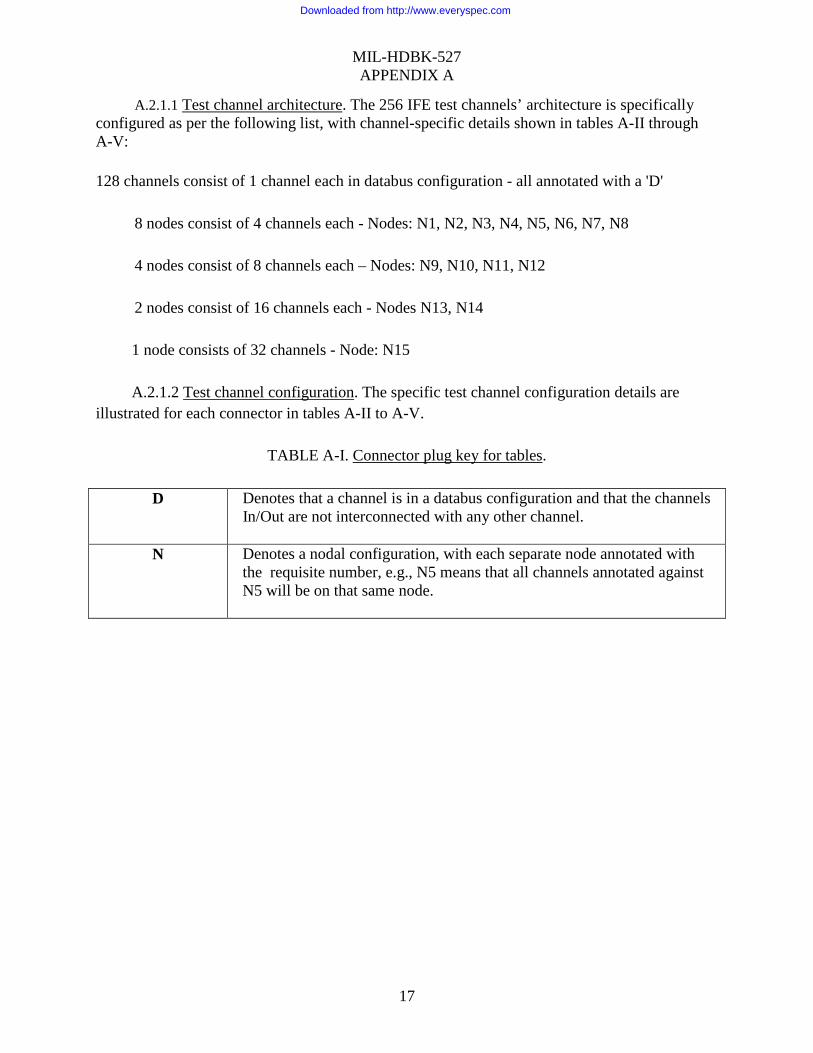
A.2.1.1 Test channel architecture. The 256 IFE test channels’ architecture is specifically configured as per the following list, with channel-specific details shown in tables A-II through A-V:
128 channels consist of 1 channel each in databus configuration - all annotated with a 'D'
8 nodes consist of 4 channels each - Nodes: N1, N2, N3, N4, N5, N6, N7, N8
4 nodes consist of 8 channels each – Nodes: N9, N10, N11, N12
2 nodes consist of 16 channels each - Nodes N13, N14
1 node consists of 32 channels - Node: N15 A.2.1.2 Test channel configuration. The specific test channel configuration details are
illustrated for each connector in tables A-II to A-V.
TABLE A-I. Connector plug key for tables.
D Denotes that a channel is in a databus configuration and that the channels In/Out are not interconnected with any other channel.
N Denotes a nodal configuration, with each separate node annotated with the requisite number, e.g., N5 means that all channels annotated against N5 will be on that same node.
Downloaded from http://www.everyspec.com

MIL-HDBK-527 APPENDIX A
18
TABLE A-II. Channel and databus/nodal configuration vs connector pins: plugs A through D.
Downloaded from http://www.everyspec.com

MIL-HDBK-527 APPENDIX A
19
TABLE A-III. Channel and databus/nodal configuration vs connector pins: plugs E through H.
Downloaded from http://www.everyspec.com

MIL-HDBK-527 APPENDIX A
20
TABLE A-IV. Channel configuration vs IFE channels 1 through 256: plugs A through D.
Downloaded from http://www.everyspec.com

MIL-HDBK-527 APPENDIX A
21
TABLE A-V. Channel configuration vs IFE channels 1 through 256: plugs E through H.
Downloaded from http://www.everyspec.com

MIL-HDBK-527 APPENDIX B
22
INTERMITTENT FAULT EMULATOR WAVEFORMS B.1 SCOPE
B.1.1 Scope. The appendix provides examples of intermittent fault waveforms that can be generated using flexible profile codes that are built into the IFE.
B.2 Background. The IFE is a useful tool in evaluating intermittent diagnostic equipment
that is very easy to set up and operate. The IFE has the ability to quickly validate diagnostic equipment capabilities. The IFE does an excellent job categorizing test equipment and gauging intermittence detection performance when testing a single wire (databus) or interconnected (nodal) circuitry. An independent evaluation of the IFE found that the IFE works extremely well on the slow-duration end of the testing spectrum (ranging from one hundred microseconds to seconds) regardless of the test stimulus (current) applied. Unfortunately, this evaluation also found that the IFE struggles to perform as necessary on the fast-duration (nanoseconds [ns]) end when low-power test stimulus is applied. Intermittence is a complex failure mode that typically begins in the nanosecond to microsecond realm. The physical root causes of intermittence are often only evident under a microscope. Simulating this low-level, complex environment is difficult, especially when a broad range of testing stimulus is considered. Solid state switches used in the IFE were the only option for providing the speed of switching required for short duration intermittent fault emulation, but there are a number of performance trade-offs. The higher the voltage requirement, the slower the speed of switching and as speed increases in the same voltage range, the amount of charge injected into the channel from these switches also increases. This unwanted injected charge changes the voltage in the switched circuit for a period that depends on the amount of current flowing in the circuit. The lower the current, the longer the voltage is not at the expected level. Therefore, a switch capable of generating a 100ns pulse-width with a voltage of up to plus or minus 15 volts will have enough charge injection as to require a current of several tens of milliamps to overcome the effects of the charge injection. Due to inherent limitations in the electronic switches used in the IFE, it will not properly gauge the ability to detect intermittence below 15 microseconds on a databus if the diagnostic equipment test stimulus is below 40 milliamps. At low-power stimulus, pulse-widths greater than 15 microseconds are more accurate, and the accuracy increases as the test current increases from 40 to 90 milliamps. The IFE performs well for simulated intermittent events employing 90 milliamps of stimulus and above, but may not provide validation of diagnostic equipment, which have test stimulus currents less than 90 milliamps, especially in nodal circuit configurations.
Downloaded from http://www.everyspec.com

Downloaded from http://www.everyspec.com

Downloaded from http://www.everyspec.com

MIL-HDBK-527 APPENDIX B
25
B.4.2 Waveform figures. Figures B-2 to B-15 illustrate waveforms that can be generated
by using the IFE flexible profile codes and show the limitations of the IFE’s ability to generate various waveforms. The input and output of a channel are normally a closed circuit, which resistive values (see table B-II) can be individually turned on or any combination can be turned on. The resistance in any given channel can vary from the inherent resistance of the closed circuit to approximately 511K ohms. The following is an explanation of the waveforms:
Figure B-2 Single pulse square wave formed by switching from a closed circuit to 500K
ohms for 100 ns duration using a 30 mA source. Figure B-3 Single pulse square wave formed by switching from a closed circuit to 500K
ohms for 1 ms duration using a 3 mA source. Figure B-4 Single pulse square wave formed by switching from a closed circuit to 500K
ohms for 1 ms duration using a 30 mA source. Figure B-5 Single pulse square wave formed by switching from a closed circuit to 500K
ohms for 1 µs duration using a 30 mA source. Figure B-6 Burst of five square waves formed by switching from a closed circuit to
500K Ohms for 10 µs duration using a 30 mA source. Figure B-7 Single pulse square wave formed by switching from a closed circuit to 500K
ohms for 10 µs duration using a 30 mA source. Figure B-8 Single pulse square wave formed by switching from a closed circuit to 500K
ohms for 100 µs duration using a 30 mA source. Figure B-9 Ramped square waves formed by switching from a closed circuit to 53, 1K,
10K and 500K ohms and back to the closed circuit for 1 ms duration using a 3 mA source.
Figure B-10 Ramped square waves formed by switching from a closed circuit to 53, 1K,
10K and 500K ohms and back to the closed circuit for 100 µs duration using a 30 mA source. Ramping up is 12.5 µs, ramping down is 12.5 µs and 75 µs at 500K ohms.
Figure B-11 Saw-tooth square waves formed by switching from a closed circuit to 53,
1K, 10K and 500K ohms and back to the closed circuit for 1ms duration using a 3 mA source. Each resistance duration is equal time up and down.
Downloaded from http://www.everyspec.com

MIL-HDBK-527 APPENDIX B
26
Figure B-12 Saw-tooth square waves formed by switching from a closed circuit to 53,
1K, 10K and 500K ohms and back to the closed circuit for a total 100 µs duration using a 30 mA source. Each resistance duration is equal in time during both the up and down cycles.
Figure B-13 Two-step square wave formed by switching from a closed circuit in two
steps at half 500K and 500K ohms for 1 ms duration using a 3 mA source. Half of the duration is spent at each resistance.
Figure B-14 Burst of five two step square wave formed by switching from a closed
circuit in two steps at half 500K and 500K ohms for 10 µs duration using a 30 mA source. In the two step square wave, half of the duration is spent at each resistance.
Figure B-15 Two-step square wave formed by switching from a closed circuit in two
steps at half 500K and 500K ohms for 100 µs duration using a 30 mA source. Half of the duration is spent at each resistance.
B.4.3 Waveform summary. There are several conclusions that can be made based on the
waveforms shown on figures B-2 through B-15.
a. As illustrated on figure B-2 the IFE is not able to fully create the required waveform in very short durations such as 100 ns on figure B-2. b. The IFE generates a significant positive and negative spike during both the opening and closing of the resistance in the channel path. This spike is due to charge injection characteristics inherent in the IFE electronic switches. The waveforms generated and spike reduction by the IFE improve as the stimulus current of the diagnostic equipment increases above 40 mA.
Downloaded from http://www.everyspec.com

MIL-HDBK-527 APPENDIX B
27
FIG
UR
E B
-2. W
avef
orm
A4
30 m
A 1
00 n
s.
Downloaded from http://www.everyspec.com

MIL-HDBK-527 APPENDIX B
28
FIG
UR
E B
-3. W
avef
orm
Q4
3 m
A 1
ms.
Downloaded from http://www.everyspec.com

MIL-HDBK-527 APPENDIX B
29
FIG
UR
E B
-4. W
avef
orm
Q4
30 m
A 1
ms.
Downloaded from http://www.everyspec.com

MIL-HDBK-527 APPENDIX B
30
FIG
UR
E B
-5. W
avef
orm
Q4
30 m
A 1
µs.
Downloaded from http://www.everyspec.com

MIL-HDBK-527 APPENDIX B
31
FIG
UR
E B
-6. W
avef
orm
Q4
30 m
A 1
0 µs
5B
.
Downloaded from http://www.everyspec.com

MIL-HDBK-527 APPENDIX B
32
FIG
UR
E B
-7. W
avef
orm
Q4
30 m
A 1
0 µs
.
Downloaded from http://www.everyspec.com

MIL-HDBK-527 APPENDIX B
33
FIG
UR
E B
-8. W
avef
orm
Q4
30 m
A 1
00 µ
s.
Downloaded from http://www.everyspec.com

MIL-HDBK-527 APPENDIX B
34
FIG
UR
E B
-9. W
avef
orm
R4
3 m
A 1
ms.
Downloaded from http://www.everyspec.com

MIL-HDBK-527 APPENDIX B
35
FIG
UR
E B
-10.
Wav
efor
m R
4 30
mA
100
µs.
Downloaded from http://www.everyspec.com

MIL-HDBK-527 APPENDIX B
36
FIG
UR
E B
-11.
Wav
efor
m S
4 3
mA
1 m
s.
Downloaded from http://www.everyspec.com

MIL-HDBK-527 APPENDIX B
37
FIG
UR
E B
-12.
Wav
efor
m S
4 30
mA
100
µs.
Downloaded from http://www.everyspec.com

MIL-HDBK-527 APPENDIX B
38
FIG
UR
E B
-13.
Wav
efor
m T
4 3
mA
1 m
s.
Downloaded from http://www.everyspec.com

MIL-HDBK-527 APPENDIX B
39
FIG
UR
E B
-14.
Wav
efor
m T
4 30
mA
10
µs 5
B.
Downloaded from http://www.everyspec.com

MIL-HDBK-527 APPENDIX B
40
FIG
UR
E B
-15.
Wav
efor
m T
4 30
mA
100
µs.
Downloaded from http://www.everyspec.com

MIL-HDBK-527 APPENDIX B
41
B.5 F/A-18 generator converter unit waveform examples. Figures B-16 through B-21 are examples of waveforms taken from an F/A -18 Generator Converter Unit (GCU). These intermittent faults were detected by Intermittent Fault Diagnostic Equipment and the waveforms were captured on an oscilloscope. All of the waveforms are of different amplitudes and durations, but coming from the same test point. These examples illustrate the importance of testing all circuits simultaneously. Figures B-16 through B-21 also show that intermittent faults do not follow a specific pattern from minute to minute during testing, which is one reason that intermittent faults are difficult to capture and detect. These waveforms are provided only as examples. Waveform duration, amplitude, and shape will vary depending on the piece of equipment and the nature of the intermittent fault (fatigue fracture, cold solder joint, poor crimp, etc.).
Downloaded from http://www.everyspec.com

MIL-HDBK-527 APPENDIX B
42
FIG
UR
E B
-16.
GC
U w
avef
orm
exa
mpl
e 1.
Downloaded from http://www.everyspec.com

MIL-HDBK-527 APPENDIX B
43
FIG
UR
E B
-17.
GC
U w
avef
orm
exa
mpl
e 2.
Downloaded from http://www.everyspec.com

MIL-HDBK-527 APPENDIX B
44
FIG
UR
E B
-18.
GC
U w
avef
orm
exa
mpl
e 3.
Downloaded from http://www.everyspec.com

MIL-HDBK-527 APPENDIX B
45
FIG
UR
E B
-19.
GC
U w
avef
orm
exa
mpl
e 4.
Downloaded from http://www.everyspec.com

MIL-HDBK-527 APPENDIX B
46
FIG
UR
E B
-20.
GC
U w
avef
orm
exa
mpl
e 5.
Downloaded from http://www.everyspec.com

MIL-HDBK-527 APPENDIX B
47
FIG
UR
E B
-21.
GC
U w
avef
orm
exa
mpl
e 6.
Downloaded from http://www.everyspec.com

MIL-HDBK-527 APPENDIX B
48
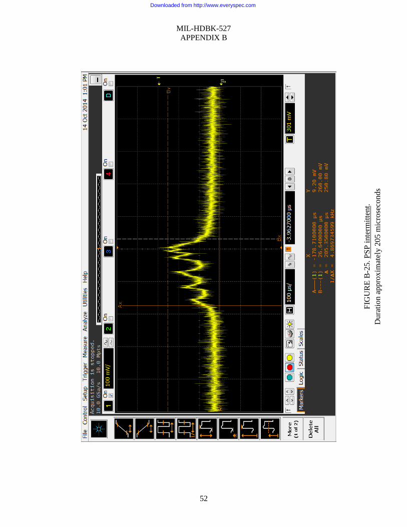
B.6 AN/APG-68 radar system programmable signal processor (PSP) waveform examples. Figures B-22 through B-26 are examples of waveforms taken from an AN/APG-68 Radar PSP. These intermittent faults were detected by Intermittent Fault Diagnostic Equipment and the waveforms were captured on an oscilloscope. All of the waveforms were detected on the same pin within the PSP and demonstrate the same intermittent event at different durations. Again as was seen in F/A-18 GCU (see B.5) example, this illustrates the importance of testing all circuits simultaneously. Figures B-22 through B-26 also demonstrate that intermittent faults do not follow a specific pattern from minute to minute during testing, which is one reason that intermittent faults again are difficult to capture and detect. These waveforms are provided only as examples. Waveform duration, amplitude and shape will vary depending on the piece of equipment and the nature of the intermittent fault (fatigue fracture, cold solder joint, poor crimp, etc.).
Downloaded from http://www.everyspec.com

MIL-HDBK-527 APPENDIX B
49
FIG
UR
E B
-22.
PSP
inte
rmitt
ent.
Dur
atio
n ap
prox
imat
ely
207
mic
rose
cond
s
Downloaded from http://www.everyspec.com

MIL-HDBK-527 APPENDIX B
50
FIG
UR
E B
-23.
PSP
inte
rmitt
ent.
Dur
atio
n ap
prox
imat
ely
163
mic
rose
cond
s
Downloaded from http://www.everyspec.com

MIL-HDBK-527 APPENDIX B
51
FIG
UR
E B
-24.
PSP
inte
rmitt
ent.
Dur
atio
n ap
prox
imat
ely
155
mic
rose
cond
s
Downloaded from http://www.everyspec.com
MIL-HDBK-527 APPENDIX B
52
FIG
UR
E B
-25.
PSP
inte
rmitt
ent.
Dur
atio
n ap
prox
imat
ely
205
mic
rose
cond
s
Downloaded from http://www.everyspec.com

MIL-HDBK-527 APPENDIX B
53
FIG
UR
E B
-26
.PSP
inte
rmitt
ent.
Dur
atio
n ap
prox
imat
ely
136
mic
rose
cond
s
Downloaded from http://www.everyspec.com

MIL-HDBK-527
54
CONCLUDING MATERIAL
Custodians: Army - MI Navy - AS Air Force - 85
Preparing activity: Navy – AS Project 6625-2017-002
Review activities: Army - AV Air Force - 99
NOTE: The activities listed above were interested in this document as of the date of this document. Since organizations and responsibilities can change, you should verify the currency of the information above using the ASSIST Online database at https://assist.dla.mil.
Downloaded from http://www.everyspec.com