department of production engineeringhithaldia.ac.in/cm/pe/lab/11. pe 691.pdf · 2017-10-25 ·...
TRANSCRIPT
DEPARTMENT OF PRODUCTION ENGINEERING HALDIA INSTITUTE OF TECHNOLOGY
LAB MANUAL ON
MACHINING TECHNOLOGY AND MACHINE TOOL SYSTEMS LABORATORY
(PE 691)
CREDIT: 2
CONTACT HOURS / WEEK: 0-0-3
Syllabus
Machining Technology and Machine Tool Systems Laboratory (PE 691)
To study the geometry of a single point turning tool and to manufacture an wooden tool in carpentry shop To manufacture intricate objects in centre lathe, milling machine shaping and to determine the machining time Study of chip formation (type, color and thickness) in turning mild steel and evaluation of shear plane angle, chip reduction coefficient, metal removal rate and total machining time in turning Measurement of cutting forces in straight turning with different feeds and velocities To study the apron mechanism of a centre lathe and determination of apron constant
(At least six experiments must be performed)
Books:
Machining and Machine Tools – A.B.Chattopadhyay
Metal Cutting Theory and Practice – A.Bhattacharyya
Principles of Machine Tools – G.C.Sen and A.Bhattacharyya
Elements of Workshop Technology, Volume 2 (Machine Tools) – S.K.Hazra Choudhary, A.K Hazra Choudhary, Nirjhar Roy

Course Outcomes:
COS PE 691.
PE 691. 1
The incumbents will be able to explain that how a cutting tool is manufactured from wood and other materials and they will be able to prepare a wooden cutting tool in a carpentry shop
PE 691. 2
The incumbents will develop an idea of how to machine a complex shaped job in centre lathe and they will also be able to perform different operations on centre lathe like cylindrical turning, taper turning, facing, knurling, grooving, threading, parting off etc
PE 691. 3
The incumbents will be able to perform cylindrical turning on a mild steel rod and will be able to measure the cutting force and chip reduction coefficient in cylindrical turning operation
PE 691. 4 The incumbents will be able to prepare a complex shaped job in shaping machine by adjusting the machining conditions and components
PE 691. 5 The incumbents will be able to explain the indexing mechanism of a milling machine and
with the help of that will be able to generate a spur gear from a cylindrical blank
PE 691. 6
The incumbents will be able to explain how the speed of the motor is transmitted through different intermediate shaft speeds from lead screw to carriage for both longitudinal feed and cross feed in a centre lathe and will be able to determine the speed ratio called apron constant

CO-PO Correlation:
COS PE 691. PO1 PO2 PO3 PO4 PO5 PO6 PO7 PO8 PO9 PO10 PO11 PO12
PE 691. 1
The incumbents will be able to explain that how a cutting tool is manufactured from wood and other materials and they will be able to prepare a wooden cutting tool in a carpentry shop
3 3 3 3 3 3 3 3 3 3 1 3
PE 691. 2
The incumbents will develop an idea of how to machine a complex shaped job in centre lathe and they will also be able to perform different operations on centre lathe like cylindrical turning, taper turning, facing, knurling, grooving, threading, parting off etc
3 3 3 3 3 3 3 3 3 3 2 3
PE 691. 3
The incumbents will be able to perform cylindrical turning on a mild steel rod and will be able to measure the cutting force and chip reduction coefficient in cylindrical turning operation
3 3 3 3 3 3 3 3 3 1 1 3
PE 691. 4
The incumbents will be able to prepare a complex shaped job in shaping machine by adjusting the machining conditions and components
3 3 3 3 3 3 3 3 3 3 - 3
PE 691. 5
The incumbents will be able to explain the indexing mechanism of a milling machine and with the help of that
will be able to generate a spur gear from a cylindrical blank 3 3 3 3 3 3 3 3 3 3 1 3
PE 691. 6
The incumbents will be able to explain how the speed of the motor is transmitted through different intermediate shaft speeds from lead screw to carriage for both longitudinal feed and cross feed in a centre lathe and will be able to determine the speed ratio called apron constant
3 3 3 3 3 3 3 3 3 3 - 3
* Enter correlation levels 1, 2 or 3 as defined below: 1: Slight (Low) 2: Moderate (Medium)3: Substantial (High) and It there is no correlation, put ―-‖
3 3 3 3 3 3 3 3 3 2.67 0.84 3

CO-PSO Correlation:
COS PE 691 PSO1 PSO2 PSO3
PE 691 1 The incumbents will be able to explain that how a cutting tool is manufactured from wood and other materials and they will be able to prepare a wooden cutting tool in a carpentry shop
3 2 3
PE 691 2
The incumbents will develop an idea of how to machine a complex shaped job in centre lathe and they will also be able to perform different operations on centre lathe like cylindrical turning, taper turning, facing, knurling, grooving, threading, parting off etc
3 3 3
PE 691 3 The incumbents will be able to perform cylindrical turning on a mild steel rod and will be able to measure the cutting force and chip reduction coefficient in cylindrical turning operation
3 3 3
PE 691 4 The incumbents will be able to prepare a complex shaped job in shaping machine by adjusting the machining conditions and components
3 2 3
PE 691 5 The incumbents will be able to explain the indexing mechanism of a milling machine and with the
help of that will be able to generate a spur gear from a cylindrical blank . 3 2 3
PE 691 6
The incumbents will be able to explain how the speed of the motor is transmitted through different intermediate shaft speeds from lead screw to carriage for both longitudinal feed and cross feed in a centre lathe and will be able to determine the speed ratio called apron constant
3 2 3
* Enter correlation levels 1, 2 or 3 as defined below: 1: Slight (Low) 2: Moderate (Medium)3: Substantial (High) and It there is no correlation, put ―-‖
3 2.33 3

CO-EXPERIMENT CORRELATION MAP:
COS PE 691. E-O1 E-O2 E-O3 E-O4 E-O5 E-O6
PE 691. 1
The incumbents will be able to explain that how a cutting tool is manufactured from wood and other materials and they will be able to prepare a wooden cutting tool in a carpentry shop
√
PE 691. 2
The incumbents will develop an idea of how to machine a complex shaped job in centre lathe and they will also be able to perform different operations on centre lathe like cylindrical turning, taper turning, facing, knurling, grooving, threading, parting off etc
√
PE 691. 3
The incumbents will be able to perform cylindrical turning on a mild steel rod and will be able to measure the cutting force and chip reduction coefficient in cylindrical turning operation
√ √
PE 691. 4
The incumbents will be able to prepare a complex shaped job in shaping machine by adjusting the machining conditions and components
√
PE 691. 5
The incumbents will be able to explain the indexing mechanism of a milling machine and with the help of that will be able to generate a spur gear from a cylindrical
blank .
√
PE 691. 6
The incumbents will be able to explain how the speed of the motor is transmitted through different intermediate shaft speeds from lead screw to carriage for both longitudinal feed and cross feed in a centre lathe and will be able to determine the speed ratio called apron constant
√ √ √
EXPERIMENT NO-1:
To make an wooden single point turning tool.
EXPERIMENT NO-2: To manufacture a threaded mandrel as per sketch
EXPERIMENT NO-3:
To manufacture a spur gear in milling machine.
EXPERIMENT NO-4:
To calculate the machining time of a shaper.
EXPERIMENT NO-5:
To compute the shear plane angle, chip reduction coefficient, metal removal rate and machining time in turning
EXPERIMENT NO-6: Dynamometry
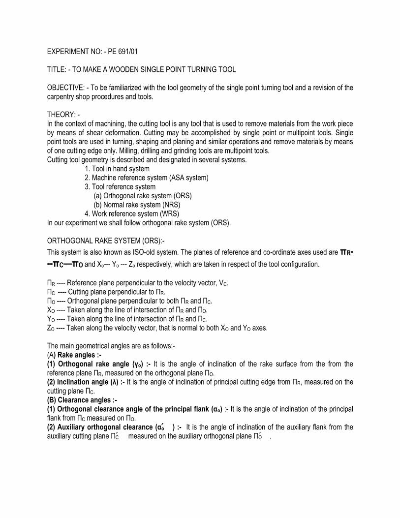
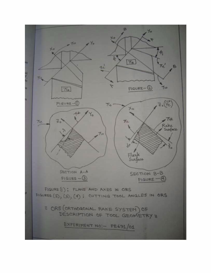
EXPERIMENT NO: - PE 691/01 TITLE: - TO MAKE A WOODEN SINGLE POINT TURNING TOOL OBJECTIVE: - To be familiarized with the tool geometry of the single point turning tool and a revision of the carpentry shop procedures and tools. THEORY: - In the context of machining, the cutting tool is any tool that is used to remove materials from the work piece by means of shear deformation. Cutting may be accomplished by single point or multipoint tools. Single point tools are used in turning, shaping and planing and similar operations and remove materials by means of one cutting edge only. Milling, drilling and grinding tools are multipoint tools. Cutting tool geometry is described and designated in several systems. 1. Tool in hand system 2. Machine reference system (ASA system) 3. Tool reference system (a) Orthogonal rake system (ORS) (b) Normal rake system (NRS) 4. Work reference system (WRS) In our experiment we shall follow orthogonal rake system (ORS). ORTHOGONAL RAKE SYSTEM (ORS):-
This system is also known as ISO-old system. The planes of reference and co-ordinate axes used are πR---πC—πO and Xo--- Yo --- Zo respectively, which are taken in respect of the tool configuration.
ΠR ---- Reference plane perpendicular to the velocity vector, VC. ΠC ---- Cutting plane perpendicular to ΠR. ΠO ---- Orthogonal plane perpendicular to both ΠR and ΠC. XO ---- Taken along the line of intersection of ΠR and ΠO. YO ---- Taken along the line of intersection of ΠR and ΠC. ZO ---- Taken along the velocity vector, that is normal to both XO and YO axes. The main geometrical angles are as follows:- (A) Rake angles :- (1) Orthogonal rake angle (γo) :- It is the angle of inclination of the rake surface from the from the reference plane ΠR, measured on the orthogonal plane ΠO. (2) Inclination angle (λ) :- It is the angle of inclination of principal cutting edge from ΠR, measured on the cutting plane ΠC. (B) Clearance angles :- (1) Orthogonal clearance angle of the principal flank (αo) :- It is the angle of inclination of the principal flank from ΠC measured on ΠO. (2) Auxiliary orthogonal clearance (αo ) :- It is the angle of inclination of the auxiliary flank from the auxiliary cutting plane ΠC measured on the auxiliary orthogonal plane ΠO .

(C) Cutting angles:- (1) Principal cutting edge angle (ϕ):- It is the angle between ΠC and the direction of assumed longitudinal feed or ΠX, measured on ΠR. (2) Auxiliary cutting edge angle (ϕ1):- It is the angle between ΠC and ΠX, measured on ΠR. The other important feature in tool geometry is nose radius. Nose radius (r, in mm):- Nose radius is the radius of curvature of the tool tip (mm). The geometry of single point turning tools is designated in ORS by ----
λ, γo, αo, αo ,ϕ1, ϕ , r (mm). MATERIAL: - Wooden piece of dimension 45 mm X 45 mm X 150 mm. TOOLS REQUIRED:- Tenon saw, steel rule, try square, G-cramp, ball peen hammer, firmer chisel, flat file, half round file, rasp file, triangular file. PROCEDURE:- In the workshop we shall have to prepare a single point wooden turning tool with principal cutting edge angle 75o, auxiliary cutting edge angle 15o, inclination angle 10o, back rake angle 6o and side rake angle 6o The following procedure is adopted for marking to make the tool. 1) Smoothen all the faces top, bottom, front, rear, left hand side and right hand side of the wooden piece by flat file and rasp file as far as possible. 2) Check the perpendicularity of the faces by means of a try square. 3) Draw a straight line AB along the 150 mm length on the middle of the top face, where points A and B are midpoints of 45 mm sides of the top face. 4) Similarly draw the straight line CD in the middle of the bottom face. 5) Draw line AE making angle (90o-75o=) 15o with AB. [Principal cutting edge angle =75o] 6) Draw line AF making angle (90o- 15o=) 75o with AB. [Auxiliary cutting edge angle =15o] 7) Find the point G on the bottom face corresponding to point E. Join the straight line CG. 8) Find the point H on the bottom face corresponding to point F. Join the straight line CH. 9) Find the point K on the straight line CD at a distance 8 mm from point C. [As height X tan (inclination angle) = 45 X tan 10o = 8 mm] 10) Draw the straight line KL parallel to CG. 11) Draw the straight line KM parallel to CH. 12) Join the straight line EL on the front face. 13) Join the straight line FM on the rear face. 14) Draw a straight line EN perpendicular to straight line AE at the point E. 15) Mark a point P along the edge at a distance 5 mm from N. Join the straight line EP. [As height X tan (side rake angle) = 45 X tan 6o= 4.72969 mm = 5 mm (approx.)] 16) Mark a point S on straight line EL on the front face at a distance 5 mm below E. [ As height X tan (back rake angle) = 45 X tan 6o = 4.72969 mm = 5 mm (approx.)] Join the point S with corner Q on the top face by a straight line. 17) Mark a point T at a distance 12 mm vertically below the point N on the rear face. [As height X tan (auxiliary cutting edge angle) = 45 X tan 15o= 12 mm]. Join the point T with corner R on the top face and point P by two different straight lines.


Now the following steps are followed for removing the wood. – 1) Hold the wooden piece (job) properly with the working bench in the carpentry shop either by carpentry bench vice or by G-cramp. 2) Remove the wedge shaped volume corresponding to the section RAF by tenon saw. 3) Remove the wedge shaped volume corresponding to the section QAE by tenon saw. 4) Remove the wedge shaped volume corresponding to the section QES by firmer chisel. 5) Remove the wedge shaped volume corresponding to the section PNT by firmer chisel and triangular file. 6) Remove the wedge shaped volume corresponding to the section FNT by firmer chisel. 7) Smoothen the unevenness of the surfaces by means of flat file. CONCLUSION:- This experiment gives an idea of the complex shape of a single point turning tool and relation between angles and dimensions and significance of the angles. This also gives an idea how a single point turning tool can be manufactured by removing excess materials.
FREQUENTLY ASKED QUESTIONS:-
1) What is rake angle? 2) What do you mean by face and flank of the tool? 3) What will happen if there is no clearance angle? 4) What do you mean by negative rake angle? 5) What do you mean by transverse feed in turning? 6) What do you mean by reference plane?
EXPERIMENT NO: -- PE 691/02 TITLE: -- TO MANUFACTURE A THREADED MANDREL AS PER SKETCH OBJECTIVE: - TO BE ACQUAINTED WITH DIFFERENT MACHINING OPERATIONS IN A CENTRE LATHE THEORY:-- Lathe is considered as one of the oldest machine tools and is widely used in industries. It is called mother of all machine tools. The primary task in a lathe is to generate cylindrical workpieces. The lathe which is used in most modern workshops is centre lathe. It consists of the following parts – bed, headstock, tailstock, carriage and feed mechanism. A mandrel, which is an accessory of a centre lathe, can be described as solid steel shaft or spindle which is used for holding bored steel parts for machining their outside surfaces on lathe. Mandrels are employed for those jobs which have a finished hole, concentric with outer surface to be machined. In our experiment we shall have to prepare a threaded mandrel as per sketch. Various operations performed in a lathe are as follows:-
1. Turning ---- (a) Straight turning (b) Step turning (shoulder turning) 2. Facing 3. Chamfering 4. Grooving 5. Knurling 6. Undercutting 7. Taper turning 8. Thread cutting 9. Forming 10. Eccentric turning 11. Drilling
12. Reaming 13. Boring 14. Tapping 15. Polishing 16. Filing 17. Spring winding 18. Spinning 19. Counter boring 20. Taper boring 21. Parting off
Here the important operations for our experiment purpose (1-8) is described below. 1) Turning: - Turning in a lathe removes excess material from the work piece to produce a cylindrical surface of required shape and size. (a) Straight turning :- The work is turned straight when it is made to rotate about the lathe axis and the tool is fed parallel to the lathe axis. The straight turning produces a cylindrical surface by removing excess metal from the work piece. (b) Step turning :-- Step turning is the process of turning different surfaces having different diameters. The work is held between the centres and the tool is moved parallel to the axis of lathe. It is also called shoulder turning.
2) Facing: - Facing is the operation of machining the ends of a piece of work to produce a flat surface square with the axis. The operation involves feeding the tool perpendicular to the axis of rotation of the work. 3) Chamfering: - Chamfering is the operation of bevelling the extreme end of the work piece. The form tool used for taper turning may be used for this purpose. Chamfering is an essential operation after thread cutting so that the nut may pass freely on the threaded work piece. 4) Grooving: -- Grooving is the process of cutting a narrow groove on the cylindrical surface of the work piece. It is often done at the end of thread or adjacent to a shoulder to leave a small margin. The groove may be square, radial or bevelled in shape. 5) Knurling: - Knurling is the process of embossing a diamond shape pattern on the surface of the work piece. The knurling tool holder has one or two hardened steel rollers with edges of required pattern. The tool holder is pressed against the rotating work. The rollers emboss the required pattern. The tool holder is fed automatically to the required length. Knurls are available in coarse, medium and fine pitches. The patterns may be straight, inclined or diamond shaped. 6) Undercutting: - It is a process of enlarging the diameter if done internally and reducing the diameter if done externally over a short length. It is useful mainly to make fits perfect. Boring tools and parting tools are used for this operation. 7) Taper turning: - A taper may be defined as an uniform increase or decrease in diameter of a piece of work measured along its length. The different methods of taper turning are as follows --- A. Form tool method B. Compound rest method C. Tailstock set over method D. Taper turning attachment method E. Combined feed method Here for our experiment purpose we shall use the compound rest method (B). Compound rest method: - The compound rest of the centre lathe is attached to a circular base graduated in degrees, which may be swivelled and clamped at any desired angle. The angle of taper is calculated using the following formula ---
tan ϕ = (D – d)/(2l) D = larger diameter, d = smaller diameter, l = length of the taper, ϕ = half taper angle. The compound rest is swivelled to the angle calculated above and clamped. Feed is given to the compound slide to generate the taper. 8) Thread cutting: - Thread cutting is one of the most important operations performed on lathe. The process of thread cutting is to produce a helical groove on a cylindrical surface by feeding the tool longitudinally. The salient points for procedure are outlined below. ---- (a) Longitudinal feed = pitch of the thread per revolution of the work piece. (b) Carriage is moved longitudinally to obtain the feed through lead screw of the spindle.
(c) A definite ratio between the longitudinal feed and rotation of the head stock spindle should be found out. It is obtained by mounting suitable number of gears on both lead screw and spindle. (d) A proper thread cutting tool is selected according to the shape of the thread. The tool is mounted on the tool post perpendicular to the axis of the work. (e) The position of tumbler gears are adjusted accordingly to the type of threads ( right hand or left hand). (f) Spindle speed is obtained through back gears. (g) Half nut lever is engaged at the right point as indicated by the thread chasing dial. (h) Depth of cut is set suitably to allow the tool to make a light cut on the work. (i) Half nut lever is engaged only during the cut. After the cut is over, half nut is disengaged the carriage is brought back to original position. (j) After the process is over thread is checked by suitable gauges. Calculation of the change wheels:--
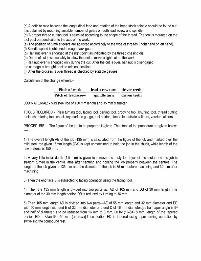
JOB MATERIAL: - Mild steel rod of 150 mm length and 35 mm diameter. TOOLS REQUIRED:- Plain turning tool, facing tool, parting tool, grooving tool, knurling tool, thread cutting tools, chamfering tool, chuck key, surface gauge, tool holder, steel rule, outside calipers, vernier calipers, PROCEDURE: -- The figure of the job to be prepared is given. The steps of the procedure are given below. ---- 1) The overall length AB of the job (135 mm) is calculated from the figure of the job and marked over the mild steel rod given.15mm length (CA) is kept unmachined to hold the job in the chuck, while length of the raw material is 150 mm. 2) A very little initial depth (1.5 mm) is given to remove the rusty top layer of the metal and the job is straight turned in the centre lathe after centring and holding the job properly between the centres. The length of the job given is 135 mm and the diameter of the job is 35 mm before machining and 32 mm after machining. 3) Then the end face B is subjected to facing operation using the facing tool. 4) Then the 135 mm length is divided into two parts viz. AD of 105 mm and DB of 30 mm length. The diameter of the 30 mm length portion DB is reduced by turning to 16 mm. 5) Then 105 mm length AD is divided into two parts—AE of 55 mm length and 32 mm diameter and ED with 50 mm length with end E of 32 mm diameter and end D of 16 mm diameter.[as half taper angle is 9o and half of diameter is to be reduced from 16 mm to 8 mm, i.e by (16-8=) 8 mm, length of the tapered portion ED = 8/tan 9o= 50 mm (approx.)].Then portion ED is tapered using taper turning operation by swivelling the compound rest.
teeth driven
teethdriver
turn spindle
turn screw lead
screw lead of Pitch
work of Pitch
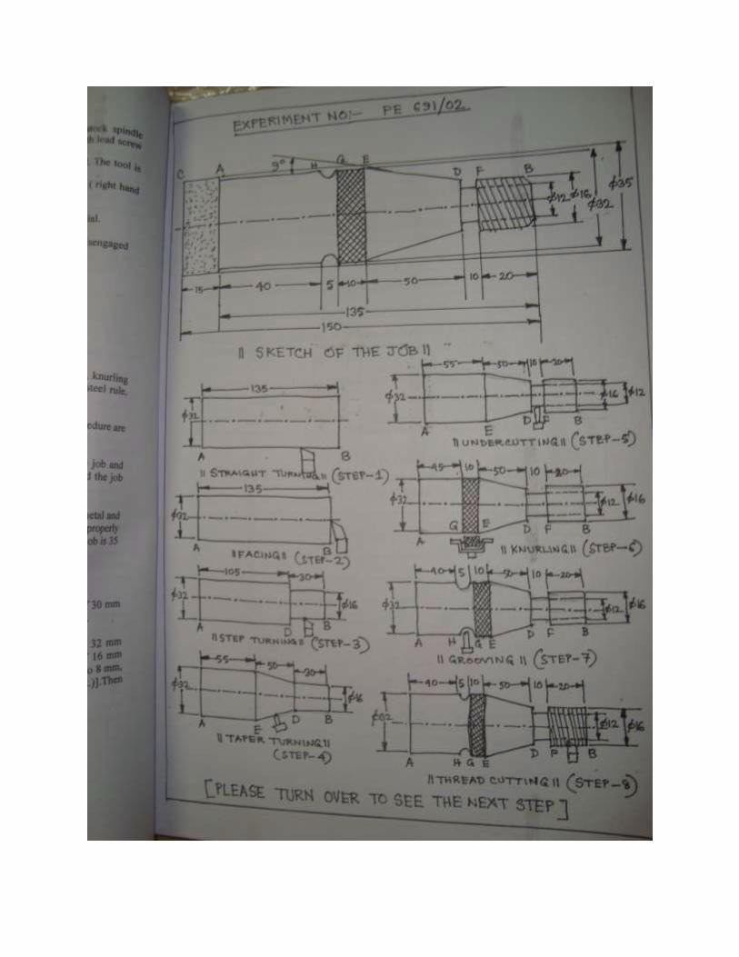
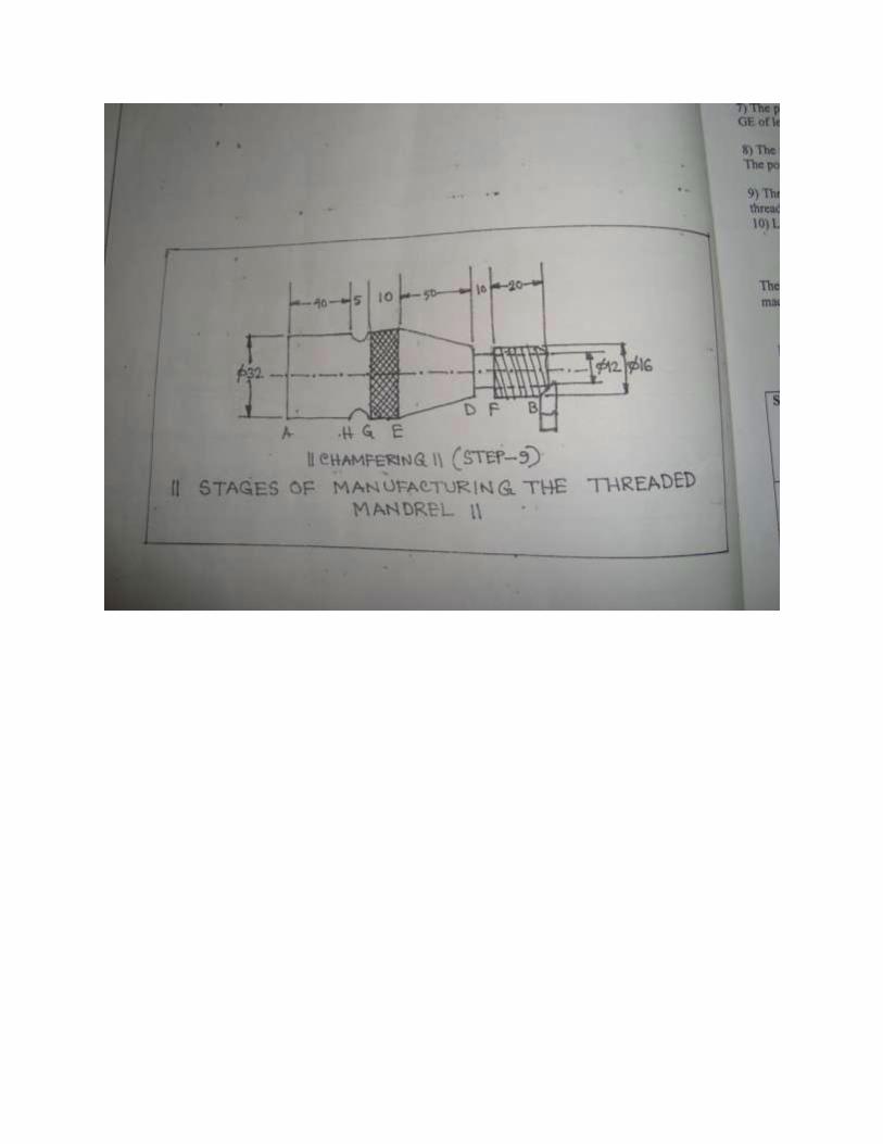

6) Now the portion DB of 30 mm length is divided into two parts DF of 10 mm length and FB of 20 mm length. The diameter of the portion DF is reduced from 16 mm to 12 mm by undercutting operation. 7) The portion AE is divided into two parts --- AG of 45 mm length and 32 mm diameter and GE of length 10 mm and 32 mm diameter. The portion GE is subjected to knurling operation. 8) The portion AG is divided into two parts --- AH of 40 mm length and HE of 5 mm length. The portion HE is given a radial groove over the cylindrical surface by using a grooving tool. 9) Thread of suitable shape (BSW/Square/Acme/Metric) is given to portion FB by means of thread cutting operation. 10) Lastly at the end B a suitable chamfer is given by chamfering operation.
[Figure of the job and figures of the operations are supplied in separate pages.] The incumbents are required to prepare the following table noting the details of the machining operations.
TABLE-1 MACHINING PLAN FOR PREPARING A THREADED MANDREL IN CENTRE LATHE
Sl.No Name of operation
Tool Dimension ( diameter in mm)
Parameters
Before After Speed Feed Depth of cut
1 Straight turning
2 Facing
3 Step turning
4 Taper turning
5 Undercutting
6 Knurling
7 Grooving
8 Thread cutting
CONCLUSION: -- This experiment gives an idea about the operations carried in a centre lathe and the tools and procedure involved with these operations. This experiment also gives an idea for process planning for a complicated job involving multiple machining operations.

FREQUENTLY ASKED QUESTIONS:--
1) What is a mandrel? 2) Name five accessories of a centre lathe. 3) What is the difference between the accessory and attachment? 4) Why the name centre lathe is given? 5) What is the function of a tool post? 6) How turning is different from facing?
EXPERIMENT NO: --- PE 691/03 TITLE: MANUFACTURE OF SPUR GEAR IN MILLING MACHINE OBJECTIVE: TO STUDY (I) INDEXING METHOD, (II) CUTTERS OF DIFFERENT TOOTH NUMBERS, (III) STUDY OF MANUFACTURE OF SPUR GEAR THEORY: By indexing we mean division of the job periphery into a desired number of divisions. It is accomplished by a controlled movement of crank such that the job rotates through a definite angle after each cut is over. The following methods of indexing are commonly used --- (i) direct indexing (ii) plain or simple indexing (iii) compound indexing (iv) differential indexing (v) angular indexing Indexing is performed by indexing or dividing heads. These heads help in changing the angular position of the component in relation to the cutter. With their use it is possible to divide the periphery of the work piece into any number of equal parts. These heads are generally of the following three types: (a) plain dividing head (b) universal dividing head (c) optical dividing heads The mostly used indexing head is universal dividing head. The salient points regarding the construction of universal dividing head are mentioned below --- (1) It consists of a fairly robust body. Enclosed in it is the worm drive, which consists of a worm and worm wheel. (2) The dividing head spindle carries a worm wheel. (3) The spindle carrying the worm which meshes with the worm wheel carries a crank at its outer end. (4) The index pin works inside the spring loaded plunger. This plunger can slide radially along a slot provided in the crank to adjust the pin position along a desired hole circle on the index plate. (5) The index plate is mounted on a sleeve on the same spindle as the crank such that the worm spindle and the crank move independent on the index plate. (6) The sector arms provided on the index plate as usually of detachable type and can be set at a desired angle with one another in order to set a definite distance along a desired hole circle. (7) The index plates are available in a set of 2 or 3, with a number of hole circles usually on both sides of them. (8) The spindle carrying the worm wheel is provided with a job carrier (driving device) and a centre at its front end. (9) On the back side of the dividing head is provided a bracket which carries a slot along its length. One or two studs, according to the requirement, can be fitted in the slot and predetermined set of change gears can be mounted on them. The index crank is rotated to provide the rotary motion to the job and the index plate enables the rotation to take place always through a desired angle. When the crank is rotated, the worm rotates, which in turn rotates the worm wheel. Since the worm wheel is directly mounted on the
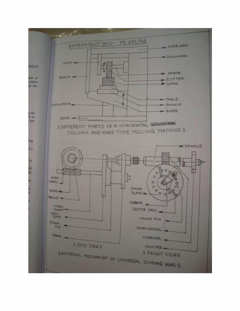
spindle, the latter rotates along with the former. The job being secured to the spindle by means of a suitable holding device also rotates as the spindle rotates. The angle, through which the job will rotate, for each revolution of the crank, depends upon the velocity ratio between the worm and worm wheel. This ratio is generally 40:1 (i.e for 40 revolutions of the crank (worm) the job will make one revolution.) The index plates are provided with a number of circles of holes on one face only (Brown and Sharp make) or on both the faces (Cincinnati and Parkinson make). There is no standard international practice for this purpose. The number of plates supplied may differ with different manufacturers. The circles provided by Brown and Sharp index plates are as follows ---
No. 1: 15, 16, 17, 18, 19, 20 No. 2: 21, 23, 27, 29, 31, 33 No. 3: 37, 39, 41, 43, 47, 49
The circles provided by Cincinnati and Parkinson index plates are as follows ---- Front: 24, 25, 28, 30, 34, 37, 38, 39, 41, 42, 43 Back: 46, 47, 49, 51, 53, 54, 57, 58, 59, 62, 66
Here in the experiment simple indexing method is followed.
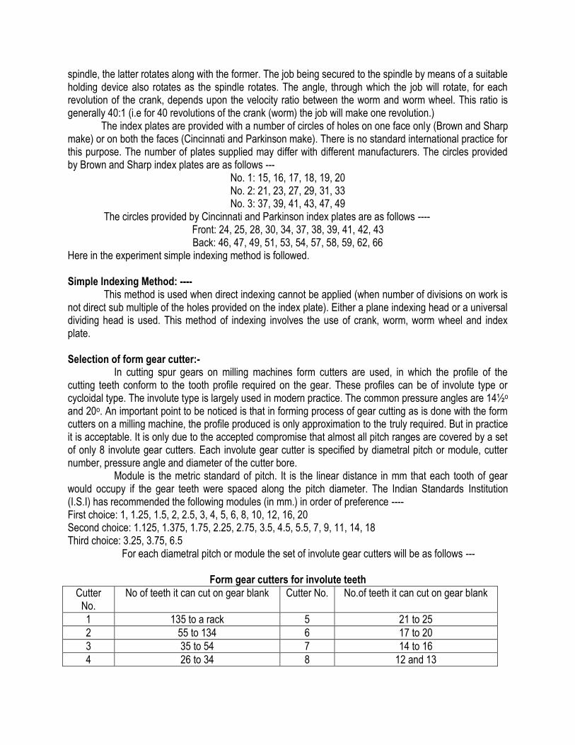
Simple Indexing Method: ---- This method is used when direct indexing cannot be applied (when number of divisions on work is not direct sub multiple of the holes provided on the index plate). Either a plane indexing head or a universal dividing head is used. This method of indexing involves the use of crank, worm, worm wheel and index plate. Selection of form gear cutter:- In cutting spur gears on milling machines form cutters are used, in which the profile of the cutting teeth conform to the tooth profile required on the gear. These profiles can be of involute type or cycloidal type. The involute type is largely used in modern practice. The common pressure angles are 14½o and 20o. An important point to be noticed is that in forming process of gear cutting as is done with the form cutters on a milling machine, the profile produced is only approximation to the truly required. But in practice it is acceptable. It is only due to the accepted compromise that almost all pitch ranges are covered by a set of only 8 involute gear cutters. Each involute gear cutter is specified by diametral pitch or module, cutter number, pressure angle and diameter of the cutter bore. Module is the metric standard of pitch. It is the linear distance in mm that each tooth of gear would occupy if the gear teeth were spaced along the pitch diameter. The Indian Standards Institution (I.S.I) has recommended the following modules (in mm.) in order of preference ---- First choice: 1, 1.25, 1.5, 2, 2.5, 3, 4, 5, 6, 8, 10, 12, 16, 20 Second choice: 1.125, 1.375, 1.75, 2.25, 2.75, 3.5, 4.5, 5.5, 7, 9, 11, 14, 18 Third choice: 3.25, 3.75, 6.5 For each diametral pitch or module the set of involute gear cutters will be as follows ---
Form gear cutters for involute teeth
Cutter No.
No of teeth it can cut on gear blank Cutter No. No.of teeth it can cut on gear blank
1 135 to a rack 5 21 to 25
2 55 to 134 6 17 to 20
3 35 to 54 7 14 to 16
4 26 to 34 8 12 and 13
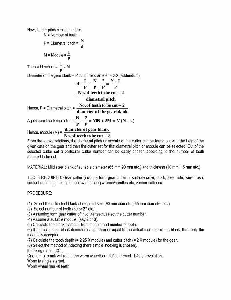
Now, let d = pitch circle diameter, N = Number of teeth,
P = Diametral pitch = d
N
M = Module =P
1
Then addendum = P
1= M
Diameter of the gear blank = Pitch circle diameter + 2 X (addendum)
= P
2d =
P
2N
P
2
P
N
= pitch diametral
2 cut be to teeth of No.
Hence, P = Diametral pitch = blankgear the ofdiameter
2 cut be to teeth of No.
Again gear blank diameter = )( 2NMM2MNP
2
P
N
Hence, module (M) = 2cut be to teeth of No.
blankgear ofdiameter
From the above relations, the diametral pitch or module of the cutter can be found out with the help of the given data on the gear and then the cutter set for that diametral pitch or module can be selected. Out of the selected cutter set a particular cutter number can be easily chosen according to the number of teeth required to be cut.
MATERIAL: Mild steel blank of suitable diameter (65 mm,90 mm etc.) and thickness (10 mm, 15 mm etc.) TOOLS REQUIRED: Gear cutter (involute form gear cutter of suitable size), chalk, steel rule, wire brush, coolant or cutting fluid, table screw operating wrench/handles etc, vernier callipers. PROCEDURE: (1) Select the mild steel blank of required size (90 mm diameter, 65 mm diameter etc.). (2) Select number of teeth (30 or 27 etc.). (3) Assuming form gear cutter of involute teeth, select the cutter number. (4) Assume a suitable module. (say 2 or 3). (5) Calculate the blank diameter from module and number of teeth. (6) If the calculated blank diameter is less than or equal to the actual diameter of the blank, then only the module is accepted. (7) Calculate the tooth depth (= 2.25 X module) and cutter pitch (= 2 X module) for the gear. (8) Select the method of indexing (here simple indexing is chosen). [Indexing ratio = 40:1, One turn of crank will rotate the worm wheel/spindle/job through 1/40 of revolution. Worm is single started. Worm wheel has 40 teeth.

For 1 division on work crank will make 40 turns. For 2 divisions on work crank will make 40/2 turns for each division. For n divisions on work crank will rotate 40/n turns for each division. If number of teeth = N, there will be N divisions of work. Hence index crank movement = 40/N. For example, for 22 divisions,
Crank movement = 11
91
11
20
22
40
To get multiple of 11, Brown and Sharp index plate number 2 can be used which have a circle with 33 number of holes.
Hence, crank movement = 33
271
311
391
11
91
i.e one full revolution of the crank + 27 holes on 33 holes circle.] (9) Calculate the index crank movement as above and select the index plate. (10) Fix the cutter on the arbor after dismantling the yoke and collars on the arbor and then again reassembling those. (11) Fix the gear blank on the spindle. (12) Set the index plate with proper circle of holes after positioning the crank with crank pin at starting position with the help of sector arms. (13) Position the table with universal dividing head so that the gear blank is very close to the cutter but is not in contact with the cutter. (14) There are two levers in the machine A and B, each of which can be set at three different positions, say 1,2 and 3. The RPM of the gear cutter can be selected from the spindle speed chart attached with the machine itself, which is given below ---
SPINDLE SPEED CHART
RPM 50 76 110 160 245 355 550 840 1225
Lever positions
A 1 1 1 3 3 3 2 2 2
B 2 3 1 2 3 1 2 3 1
(15) Choose a suitable lower RPM to avoid the breakage of the cutter and damage of the machine (here A is set at position 1 and B is also set at 1 to set the RPM at 110). (16) Switch on the machine, so that the cutter starts rotating. (17) Slowly but firmly advance the blank towards the rotating cutter until the physical contact is made. Still slowly advance the job till crest for one teeth is cut. (18) Withdraw the blank from the cutter. (19) Reset the blank by rotating the spindle with the help of index plate. (20) Advance the blank slowly again till the crest for the next teeth is cut. This actually completes cutting of one tooth.. (21) Same procedure is repeated until all the teeth are cut.[Incumbents are to cut minimum 4-5 teeth per group].

CONCLUSION: This experiment gives an idea of milling machine and its functioning, machining a complicated job in milling machine, use of universal dividing head and indexing methods, gear cutters and its selection and although in a small scale still an idea of manufacture of spur gear.
FREQUENTLY ASKED QUESTIONS:- 1) How milling is different from turning? 2) What is the function of a telescopic feed rod? 3) What is an arbor? 4) What are compound indexing and differential indexing? 5) How up-milling is different from down milling? 6) What do you mean by straddle milling and gang milling?
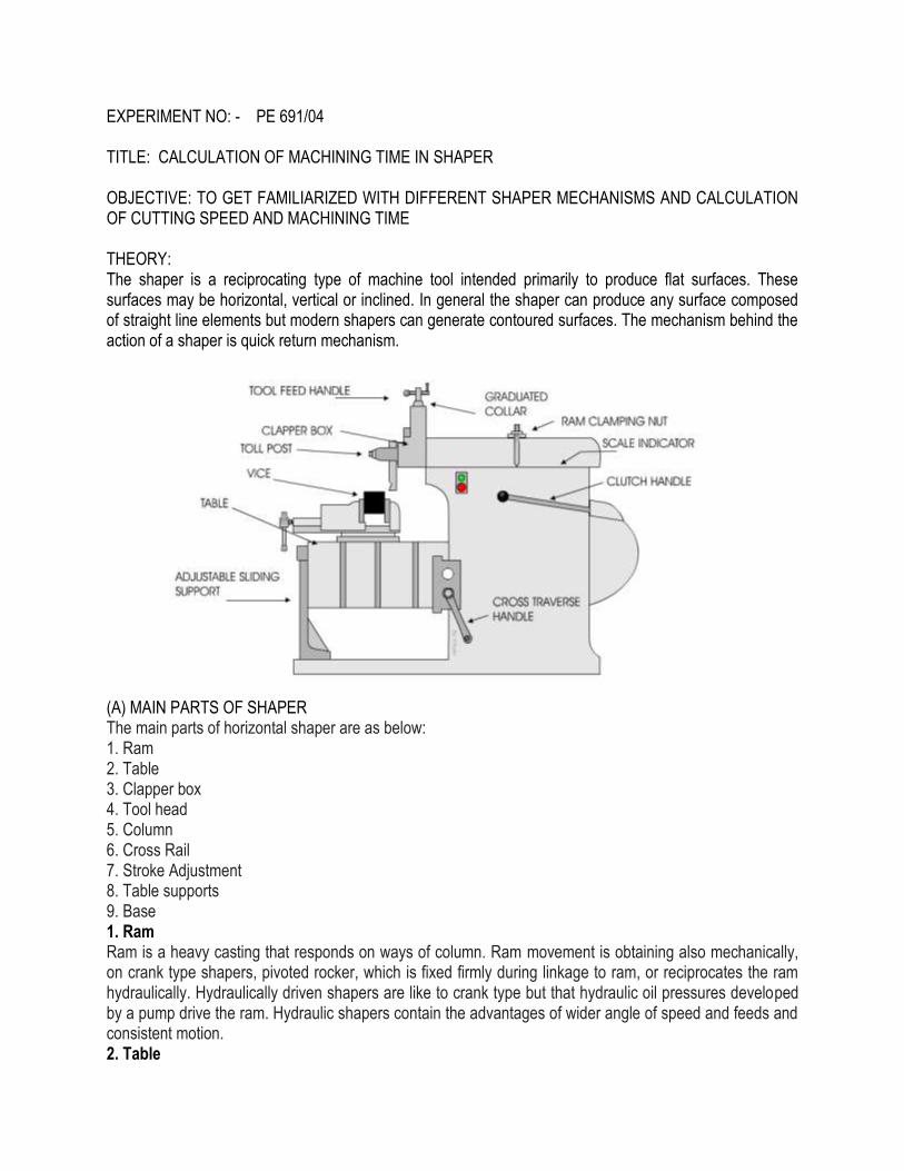
EXPERIMENT NO: - PE 691/04 TITLE: CALCULATION OF MACHINING TIME IN SHAPER OBJECTIVE: TO GET FAMILIARIZED WITH DIFFERENT SHAPER MECHANISMS AND CALCULATION OF CUTTING SPEED AND MACHINING TIME THEORY: The shaper is a reciprocating type of machine tool intended primarily to produce flat surfaces. These surfaces may be horizontal, vertical or inclined. In general the shaper can produce any surface composed of straight line elements but modern shapers can generate contoured surfaces. The mechanism behind the action of a shaper is quick return mechanism.
(A) MAIN PARTS OF SHAPER The main parts of horizontal shaper are as below: 1. Ram 2. Table 3. Clapper box 4. Tool head 5. Column 6. Cross Rail 7. Stroke Adjustment 8. Table supports 9. Base 1. Ram Ram is a heavy casting that responds on ways of column. Ram movement is obtaining also mechanically, on crank type shapers, pivoted rocker, which is fixed firmly during linkage to ram, or reciprocates the ram hydraulically. Hydraulically driven shapers are like to crank type but that hydraulic oil pressures developed by a pump drive the ram. Hydraulic shapers contain the advantages of wider angle of speed and feeds and consistent motion. 2. Table

Table is mounting on way to moves on horizontal way of cross rail. Table is void container casting by machined T-slots on the top and sides. Vise is generally fixed firmly to top of table to hold work piece. There are two kind of tables Plain and Universal. Plain table is able of horizontal and vertical actions only and universal table, in addition to affecting horizontally and vertically be able to swivel to machine angles on job. 3. Clapper box Clapper box is hanged to tool slide. It can be rotate a small sum in each direction. Clapper box have to be correctly placed while make vertical or angular cuts so tool will swing out with away as of the work piece to give the clearance on swing out and away as of the work piece to give clearance on return stroke. For horizontal cuts, clapper box is generally positioned vertically. Shaper cutting tool is held in tool post on clapper box on cutting stroke the pressure as of the cutting tool holds clapper box resolutely beside the tool head. 4. Tool head Tool head is fixed to front of ram and be able to swivel for make angular nuts. It has tool post with tool holder that hold cutting tool. Tool slide is moved lip or down by a feed screw to regulate for correct depth of cut. 5. Column Column is void casting mount directly on base housing the working, mechanism to force the ram. Upper surface of column has two precision machined conducts on which ram respond. Front face of column has to be machined at right angles to ram conduct on top of column. 6. Cross Rail Cross rail permit vertical and horizontal movement of table. Cross feed mechanism is attached to cross rail. 7. Stroke Adjustment Reciprocate movement of ram of a shaper is gain by the mechanism. Drive pinion rotate the bull wheel at consistent speed. On the side of bull wheel is a rocker arm have a slot by a diabolic, which is free to slide. Die block is attached by a crank pin to bull wheel. Radius of revolution of crank pin which manages length of the stroke is too changeable as it is fixed to a block sliding in a dovetail slot on bull wheel. 8. Table supports Table supports extend as of outer surface of table to the base and is use on some larger shapers to support the weight of table. 9. Base Base is a heavy casting to supports all main element parts of machine. (B) OPERATION OF A SHAPER Work-piece is firmly fixed on machine table. Single point cutting tool held correctly on tool post is mount on a reciprocate ram. Reciprocate movement of ram is obtain by a fast return motion machinery. Because the ram reciprocates, tool cuts the material during its forward stroke. Through go back, there is no cutting action and this stroke is called the idle stroke. Forward and return strokes form one working cycle of shaper.
(C) QUICK RETURN MECHANISMS: The quick return mechanisms mainly are of 3 types. (i) Crank and slotted link mechanism (ii) Whitworth quick return mechanism (iii) Hydraulic mechanism
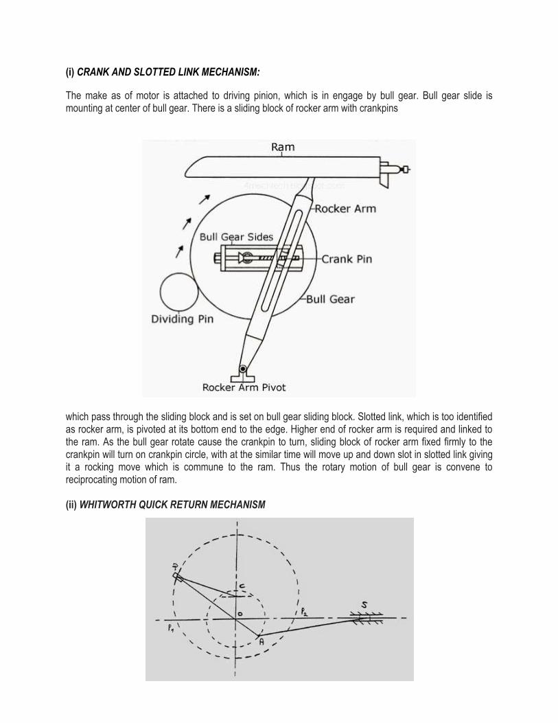
(i) CRANK AND SLOTTED LINK MECHANISM:
The make as of motor is attached to driving pinion, which is in engage by bull gear. Bull gear slide is mounting at center of bull gear. There is a sliding block of rocker arm with crankpins
which pass through the sliding block and is set on bull gear sliding block. Slotted link, which is too identified as rocker arm, is pivoted at its bottom end to the edge. Higher end of rocker arm is required and linked to the ram. As the bull gear rotate cause the crankpin to turn, sliding block of rocker arm fixed firmly to the crankpin will turn on crankpin circle, with at the similar time will move up and down slot in slotted link giving it a rocking move which is commune to the ram. Thus the rotary motion of bull gear is convene to reciprocating motion of ram. (ii) WHITWORTH QUICK RETURN MECHANISM
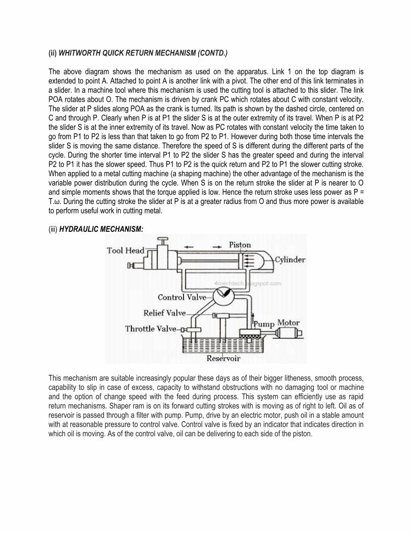
(ii) WHITWORTH QUICK RETURN MECHANISM (CONTD.) The above diagram shows the mechanism as used on the apparatus. Link 1 on the top diagram is extended to point A. Attached to point A is another link with a pivot. The other end of this link terminates in a slider. In a machine tool where this mechanism is used the cutting tool is attached to this slider. The link POA rotates about O. The mechanism is driven by crank PC which rotates about C with constant velocity. The slider at P slides along POA as the crank is turned. Its path is shown by the dashed circle, centered on C and through P. Clearly when P is at P1 the slider S is at the outer extremity of its travel. When P is at P2 the slider S is at the inner extremity of its travel. Now as PC rotates with constant velocity the time taken to go from P1 to P2 is less than that taken to go from P2 to P1. However during both those time intervals the slider S is moving the same distance. Therefore the speed of S is different during the different parts of the cycle. During the shorter time interval P1 to P2 the slider S has the greater speed and during the interval P2 to P1 it has the slower speed. Thus P1 to P2 is the quick return and P2 to P1 the slower cutting stroke. When applied to a metal cutting machine (a shaping machine) the other advantage of the mechanism is the variable power distribution during the cycle. When S is on the return stroke the slider at P is nearer to O and simple moments shows that the torque applied is low. Hence the return stroke uses less power as P = T.ω. During the cutting stroke the slider at P is at a greater radius from O and thus more power is available to perform useful work in cutting metal. (iii) HYDRAULIC MECHANISM:
This mechanism are suitable increasingly popular these days as of their bigger litheness, smooth process, capability to slip in case of excess, capacity to withstand obstructions with no damaging tool or machine and the option of change speed with the feed during process. This system can efficiently use as rapid return mechanisms. Shaper ram is on its forward cutting strokes with is moving as of right to left. Oil as of reservoir is passed through a filter with pump. Pump, drive by an electric motor, push oil in a stable amount with at reasonable pressure to control valve. Control valve is fixed by an indicator that indicates direction in which oil is moving. As of the control valve, oil can be delivering to each side of the piston.
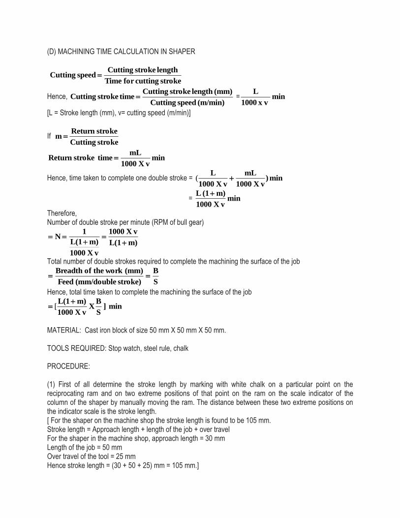
(D) MACHINING TIME CALCULATION IN SHAPER
stroke cuttingfor Time
length stroke Cutting speed Cutting
Hence, (m/min) speed Cutting
(mm) length stroke Cutting time stroke Cutting = min
vx 1000
L
[L = Stroke length (mm), v= cutting speed (m/min)]
If stroke Cutting
stroke Return m
min v X1000
mL time stroke Return
Hence, time taken to complete one double stroke = min )v X1000
mL
v X1000
L(
= min v X1000
m)(1 L
Therefore, Number of double stroke per minute (RPM of bull gear)
m)L(1
v X1000
v X1000
m)L(1
1 N
Total number of double strokes required to complete the machining the surface of the job
S
B
stroke) (mm/double Feed
(mm) work the of Breadth
Hence, total time taken to complete the machining the surface of the job
min ] S
B X
v X1000
m)L(1 [
MATERIAL: Cast iron block of size 50 mm X 50 mm X 50 mm. TOOLS REQUIRED: Stop watch, steel rule, chalk PROCEDURE: (1) First of all determine the stroke length by marking with white chalk on a particular point on the reciprocating ram and on two extreme positions of that point on the ram on the scale indicator of the column of the shaper by manually moving the ram. The distance between these two extreme positions on the indicator scale is the stroke length. [ For the shaper on the machine shop the stroke length is found to be 105 mm. Stroke length = Approach length + length of the job + over travel For the shaper in the machine shop, approach length = 30 mm Length of the job = 50 mm Over travel of the tool = 25 mm Hence stroke length = (30 + 50 + 25) mm = 105 mm.]

(2) Fix the cast iron block in vice attached with the table of the shaper. (3) Fix the tool on the tool post of the tool head of the shaper. (4) Position the tool head at the extreme backward position by moving the ram. (5) Here the direction of feed is perpendicular to the direction of movement of tool. Let us assume that one cutting cycle comprises of a single cutting stroke and a single return stroke. (6) One incumbent is engaged to measure the time required for cutting stroke (t) with a stop watch. (7) Another incumbent is engaged to count the total number of cycles (cutting stroke+ return stroke) to complete the machining.[In the present situation, total number of cycles = 190]. (8) Feed is obtained as, ---
stroke mm/double cycles ofnumber Total
job the of Breadth SFeed )(
(9) As a standard practice, cutting time in a shaper = 1.5 X return stroke, take the value of m as 2/3. (10) Determine the cutting speed. (11) Determine the time required to complete the machining. OBSERVATION AND CALCULATION: Stroke length = L = _______________ Breadth of the work = B = _____________ Feed = S = ______________ m = 2/3 Time required for cutting stroke = t = _________ Cutting speed = v = L /t = ___________
Total time taken for machining = min ] S
B X
v X1000
m)L(1 [ = ______________
CONCLUSION: From this experiment the incumbents will learn about the components of shaper machine and their functioning, the crank and slotted link mechanism of the shaper and will be able to calculate the machining time in shaper.
FREQUENTLY ASKED QUESTIONS:-
1) What surface is generated by a shaper? 2) Is it possible to produce a V-block by shaper? 3) What is the difference between a shaper and a planer? 4) Why return time is less than cutting time? 5) What do you mean by position of a stroke of a shaper? 6) What is feed of a shaper?
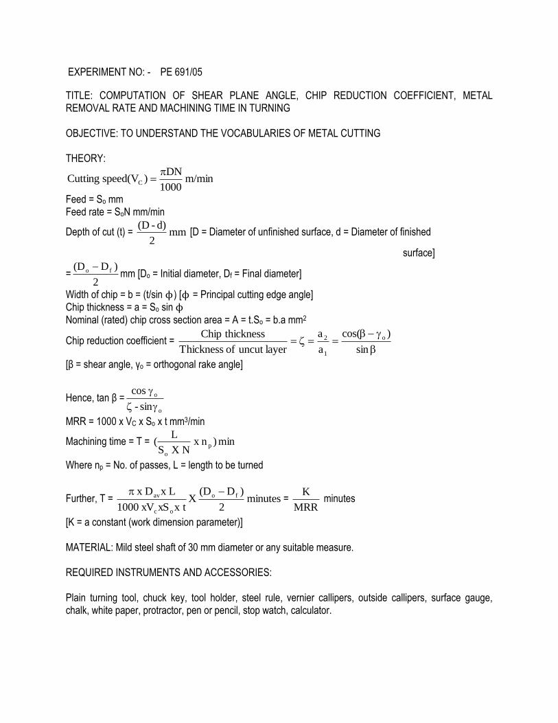
EXPERIMENT NO: - PE 691/05
TITLE: COMPUTATION OF SHEAR PLANE ANGLE, CHIP REDUCTION COEFFICIENT, METAL REMOVAL RATE AND MACHINING TIME IN TURNING OBJECTIVE: TO UNDERSTAND THE VOCABULARIES OF METAL CUTTING THEORY:
m/min 1000
DN)speed(V Cutting C
Feed = So mm Feed rate = SoN mm/min
Depth of cut (t) = mm 2
d)-(D [D = Diameter of unfinished surface, d = Diameter of finished
surface]
=2
)D(D fo mm [Do = Initial diameter, Df = Final diameter]
Width of chip = b = (t/sin ϕ) [ϕ = Principal cutting edge angle] Chip thickness = a = So sin ϕ Nominal (rated) chip cross section area = A = t.So = b.a mm2
Chip reduction coefficient =
sin
)cos(
a
a
layeruncut of Thickness
thicknessChip o
1
2
[β = shear angle, γo = orthogonal rake angle]
Hence, tan β =o
o
sin-
cos
MRR = 1000 x VC x So x t mm3/min
Machining time = T = min)n x N X S
L( p
o
Where np = No. of passes, L = length to be turned
Further, T = minutes 2
)D(D X
txxS xV1000
L xD x fo
oc
av =
MRR
K minutes
[K = a constant (work dimension parameter)] MATERIAL: Mild steel shaft of 30 mm diameter or any suitable measure. REQUIRED INSTRUMENTS AND ACCESSORIES: Plain turning tool, chuck key, tool holder, steel rule, vernier callipers, outside callipers, surface gauge, chalk, white paper, protractor, pen or pencil, stop watch, calculator.

PROCEDURE: (1) A plain turning tool is mounted on the tool post and their cutting edges are set exactly aligned to the axis of the lathe spindle. (2) The compound rest is set at 0o mark. (3) The metal piece to be machined is held in the chuck of the lathe. (4) Surface gauge is used to check whether the work is held aligned with lathe axis. (5) Spindle speed is adjusted by calculating the cutting speed. (6) A suitable cutting length L is decided to be machined in x seconds. Hence feed rate is given by ---
Feed rate = mm/min 60 X x
L
(7) From feed rate feed is calculated. (8) Marking is done on the work at the required point to indicate the length to be plain turned. (9) The cross slide is adjusted for required depth of cut and the lathe is switched on. (10) The plain turning tool mounted on the tool post is given feed by the carriage parallel to the lathe axis. (11) The above process is repeated until the required diameter is obtained. Required diameter is obtained by gradually moving the cross slide after each cut. (12) The time taken is noted by the stop watch. If more than one passes are given time per pass is calculated by dividing total machining time by number of passes. (13) The observed time is verified with experimental time. (14) During the process diameter is checked by vernier callipers or outside callipers and steel rule. (15) The chip thickness after cut is measured by vernier callipers. (16) The orthogonal rake angle is observed by taking impression of the principal flank surface containing principal cutting edge angle on a white paper. (17) The principal cutting edge angle is observed by taking the impression of rake surface of the tool on white paper. OBSERVATIONS:
TABLE-1
Sl.No Machining particulars Values for the run
1 RPM
2 Initial diameter (mm)
3 Final diameter (mm)
4 Cutting length (mm in sec.)
5 Feed rate
6 Feed
7 Cutting speed
8 Principal cutting edge angle (PCEA)
9 Depth of cut
10 Chip width
11 Chip thickness before cut
12 Orthogonal rake angle
13 MRR
14 Chip thickness after cut
15 Chip reduction coefficient
16 Shear plane angle
17 Total machining time
CALCULATIONS: [TO BE DONE BY THE INCUMBENT] PRECAUTIONS: (i) The job piece must be centred in the chuck properly. (ii) Tool in the tool post must be clamped tightly and should be aligned properly with the job piece. (iii) Arbitary feed neither should be too high, nor should be too less. (iv) Orthogonal rake angle and principal cutting edge angle should be calculated by taking and interpreting the impressions very carefully. CONCLUSIONS: In machining material is removed in the form of chips. Machining of different work materials produces different types and patterns of chips. Chips are categorized based on size, shape and colour as favourable chip and unfavourable chip indicating good and poor machinability. To understand the optimum machining conditions tool geometry, value of process parameters like feed, spindle speed and depth of cut play significant roles. But practically machining outputs are affected by tool geometry, tool materials, positioning of tool, spindle speed, feed and depth of cut and their interactions are also very complex in nature. At the end of the day we have to choose the machining conditions that optimize the machining outputs.
FREQUENTLY ASKED QUESTIONS:- 1) What is a chip? 2) How nature of chip depends on the work material? 3) Why chip thickness is more than thickness of uncut layer? 4) What do you mean by shear plane angle? 5) Is shear plane angle related with chip reduction coefficient? 6) How we can determine cutting ratio without actually measuring chip thickness?

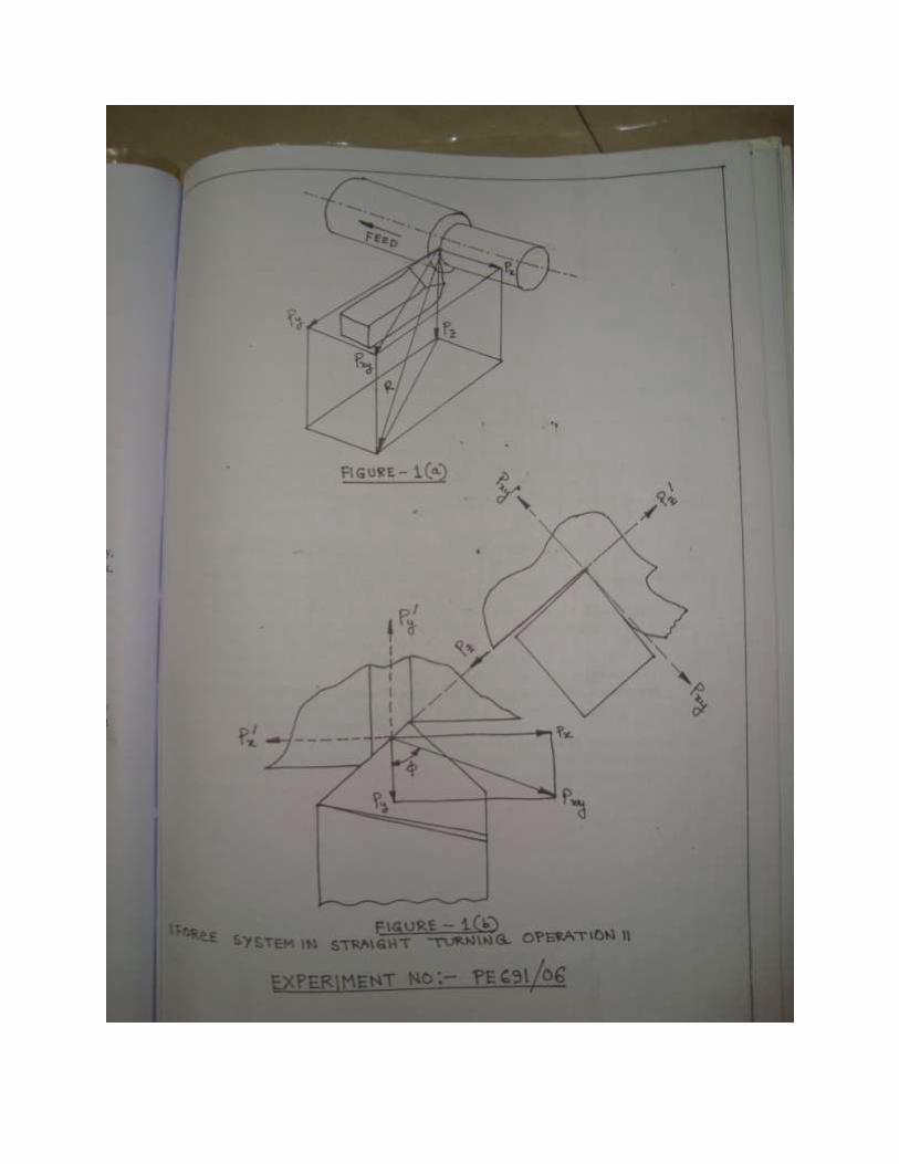
EXPERIMENT NO: - PE 691/06 TITLE: DYNAMOMETRY OBJECTIVE: (I) TO ASCERTAIN THE BENEFITS AND STATE THE PURPOSES OF DETERMINING CUTTING FORCES (II) TO IDENTIFY THE CUTTING FORCE COMPONENTS AND CONCEIVE THEIR ROLE AND SIGNIFICANCE (III) TO DEVELOP MERCHANT’S CIRCLE DIAGRAM AND SHOW THE FORCES AND THEIR RELATIONS THEORY: In machine tool, electric energy is converted to mechanical energy which is utilized to deform the material to obtain desired shape, size and other attributes. For the purpose of qualitative analysis of metal cutting process, it is therefore essential to determine the cutting forces encountered during machining, which in turn, form the basis of computation of power. The devices used for measurements of forces are called ‘dynamometers’ and the related subject is called ‘dynamometry’. The magnitude and direction of cutting force vary depending on the category of machining and cutting tools used. However the resultant force can be resolved into three mutually perpendicular components, viz. Px
(feed force), Py (thrust force), Pz (cutting force). The force system in case of straight turning operation is depicted in figures 1(a) and 1(b). The resultant force R can be resolved into Px (feed force) acting along a horizontal plane, but opposite to the direction of feed, Py (thrust force) acting perpendicular to the generated surface and Pz or cutting force which is the main force and responsible for consumption of power. If RPM = N, Initial diameter = Do mm Final diameter = Df mm Cutting length = L mm Time required to cut length L mm = x seconds
Feed rate = SoN = mm/min 60 x x
L
Feed = So mm/revolution
Average diameter = Dav = mm 2
DD fo
Depth of cut = t = mm 2
DD fo .
Cutting speed = Vc = m/min 1000
NDav
Uncut the chip thickness = a1 = Sosinϕ mm If chip thickness = a2 mm
Chip reduction coefficient = 1
2
a
a

Shear plane angle (βo) = tan-1 )sin-
cos(
o
o
If feed force = Px N Thrust force = Py N Cutting force = Pz N Shear force acting along shear plane = Ps = Pz cos βo – Pxy cos βo Force acting normal to shear plane = Pn = Pz sin βo + Pxy sin βo Frictional force acting along rake surface = F = Pxy Normal force acting perpendicular to rake surface = N = Pz
Apparent coefficient of friction = N
F
Specific cutting pressure = Ks = 2
o
yN/mm
x tS
P
Power consumed = P = kW 60 x 1000
V x P cz
Unit power consumption = Pu = min/Joule/mm x tS x 1000
P 2
o
z
MATERIAL REQUIRED: Mild steel rod of 25 mm-30 mm diameter TOOLS REQUIRED: Sensor based stainless steel turning tool, interface cables, dynamometer with digital display, chuck key, tool holder, steel rule, vernier callipers, outside callipers, surface gauge, chalk, white paper, protractor, pen or pencil, stop watch, calculator. TOOL SIGNATURE: 0o—0o—6o—6o—46o—46o—0.2 mm (ORS) PROCEDURE: Let us consider a straight turning operation. (1) The conventional tool post is replaced by a sensor based tool post. (2) The interface cable is connected between the sensor based tool post and digital display panel. It is to be taken care of that the display unit should be placed in a stable table at perfect horizontal position parallel to the ground level. (3) The compound rest is set at mark 0o. (4) The metal piece to be machined is held in the chuck of the lathe. (5) Surface gauge is used to check whether the work is held aligned with lathe axis. (6) A particular RPM (spindle speed) is set by calculating the cutting speed. (7) A suitable cutting length L is decided to be machined in x seconds. Hence feed rate is given by ---
Feed rate = mm/min 60 X x
L
(8) From feed rate feed is calculated.


(14) In the mean time two incumbents are engaged to measure the components of force in x,y and z directions from digits displayed (unit is kgf) in the panel. The incumbents are suggested to make a table as follows and note down the values over a period of time as during machining the cutting force varies initially.
X (kgf) Y (kgf) Z (kgf)
When the values of X (Px), Y (Py) and Z (Pz) become constant, the machining becomes stable. The incumbents are suggested to use this stable values of X, Y and Z for calculations. (15) The diameter of the job is measured after the machining is over by outside callipers and/or vernier callipers. (16) The chip thickness after cut is measured by vernier callipers. (17) The orthogonal rake angle is observed by taking impression of the principal flank surface containing principal cutting edge angle on a white paper. (18) The principal cutting edge angle is observed by taking the impression of rake surface of the tool on white paper. CONSTRUCTION OF MERCHANT’S CIRCLE DIAGRAM (MCD): (1) Draw the section of the tool with orthogonal rake angle (γo) = 0o, orthogonal clearance angle of the principal flank (αo) = 6o. The tool tip is denoted as O. (2) Taking a scale of 1 mm =1.25 kgf , draw a vertical straight line OA indicating Pz. (3) At point A taking the same scale draw a straight line AB perpendicular to OA indicating Pxy , such that Pxy
2= (Px2 + Py
2). (4) Join the straight line OB. OB indicates the resultant force R. (5) At point O draw a straight line OC parallel and equal to AB. OC indicates F. (6) Join the straight line BC. BC indicates the force N in the same scale. (7) Taking OB as diameter of the circle draw a circle touching all the points O, A, B and C. This circle is the desired Merchant’s Circle. (8) Draw another straight line at an angle equal to shear angle (βo) with the straight line OA. That straight line intersects the circle at point E. Join the points E and B by another straight line. OE indicates shear force acting along shear plane (Ps) in the same scale. EB indicates force acting normal to shear plane (Pn) in the same scale.

OBSERVATIONS:
TABLE -1
Sl.No. Particulars Values for the run
1 RPM
2 Initial diameter (mm)
3 Final diameter (mm)
4 Cutting length (mm in .... sec)
5 Feed rate (mm/min)
6 Feed (mm/rev)
7 Cutting speed (m/min)
8 Principal cutting edge angle (approach angle)
9 Orthogonal rake angle
10 Depth of cut (mm)
11 Uncut chip thickness (mm)
12 Cut chip thickness (mm)
13 Chip reduction coefficient
14 Shear plane angle
15 Feed force (Newton)
16 Thrust force (Newton)
17 Cutting force (Newton)
18 Shear force acting along shear plane (Newton)
19 Force acting normal to shear plane (Newton)
20 Frictional force acting along rake surface (Newton)
21 Normal force perpendicular to rake surface (Newton)
22 Apparent coefficient of friction
23 Specific cutting pressure (N/mm2)
24 Power consumption (kW)
25 Unit power consumption (Joule/mm2/min)
CALCULATIONS: [TO BE DONE BY THE INCUMBENT] PRECAUTIONS: (1) Sensor based tool post is quite expensive, so mounting and un-mounting and handling must be done with care. (2) It is to be taken care of that the display unit should be placed in a stable table at perfect horizontal position parallel to the ground level. (3) It is better to observe the forces in the digital dynamometer for a certain period and then take the average of the stable values.

CONCLUSIONS: The force analysis of turning operation using Merchant’s Circle Diagram is more or less accurate but main drawback is that instead of getting actual coefficient of friction we are getting apparent coefficient of friction (μ). And calculations are based on only orthogonal cutting. We get no idea about oblique cutting. FREQUENTLY ASKED QUESTIONS:- 1) What is a dynamometer? 2) What is the principle of measuring force by piezoelectric crystal? 3) State and explain the function of a Wheastone Bridge. 4) What is a galvanometer? What is its function in a potentiometer? 5) What is Merchant’s circle? What is its purpose? 6) Which component of machining force is related to power required by a machine?
.
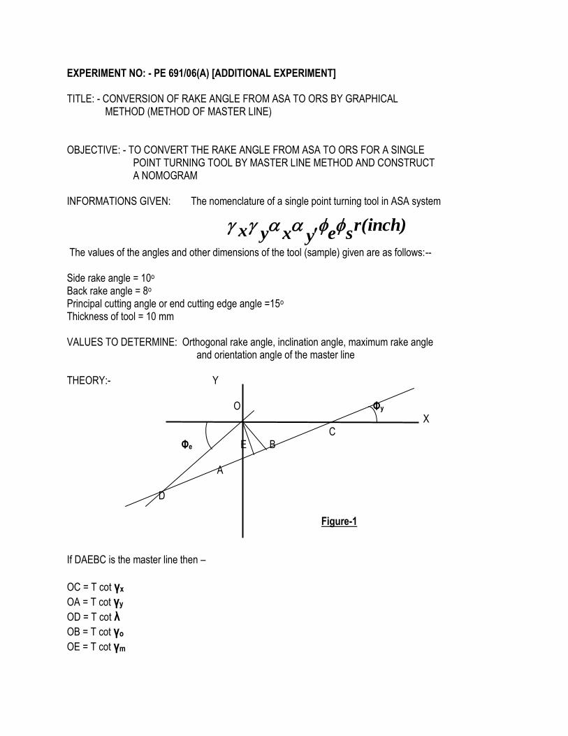
EXPERIMENT NO: - PE 691/06(A) [ADDITIONAL EXPERIMENT] TITLE: - CONVERSION OF RAKE ANGLE FROM ASA TO ORS BY GRAPHICAL METHOD (METHOD OF MASTER LINE) OBJECTIVE: - TO CONVERT THE RAKE ANGLE FROM ASA TO ORS FOR A SINGLE POINT TURNING TOOL BY MASTER LINE METHOD AND CONSTRUCT A NOMOGRAM INFORMATIONS GIVEN: The nomenclature of a single point turning tool in ASA system The values of the angles and other dimensions of the tool (sample) given are as follows:-- Side rake angle = 10o Back rake angle = 8o Principal cutting angle or end cutting edge angle =15o Thickness of tool = 10 mm VALUES TO DETERMINE: Orthogonal rake angle, inclination angle, maximum rake angle and orientation angle of the master line THEORY:- Y O Φy X C Φe E B
A D Figure-1 If DAEBC is the master line then –
OC = T cot γx
OA = T cot γy
OD = T cot λ
OB = T cot γo
OE = T cot γm
r(inch)seyxyx

Sign conventions are given below. γy-
γo- λ-
γx- γx+
O
λ+
γo+ Figure-2
γy+
The mathematical relation for conversion of rake angle from Orthogonal Rake System (ORS) to American Standard Association (ASA) system is given below.
tan
tan
sincos
cossin
tan
tan
y
x o
The mathematical relation for conversion of rake angle from American Standard Association (ASA) system to Orthogonal Rake System (ORS) is given below.
y
xo
tan
tan
sincos
cossin
tan
tan
The maximum rake angle is given by the following relation,--
yxm tantantan 22
22 tantan o
Orientation angle of master line (Φy) is given by, --
Φy = tan-1 ( tan γx/ tan γy) = Φ – tan-1 (tan λ/ tan γo)
PROCEDURE:- (1) Construct X and Y axes.
(2) Mark cutoffs T cot γx on X-axis and T cot γy on Y-axis.
(3) Draw Φe at O indicating the principal cutting edge. (4) This plane of paper is considered as reference plane.(πR). (5) Join AC and extend it to meet the trace of the principal cutting edge in the plane view at D. (6) Construct a perpendicular on OD at O to meet CD at B. Now ,--
OB = T cot γo OD = T cot λ (7) A perpendicular is dropped from O to E on the margin line DABC. If γm is the maximum
rake angle, OE is determined as below, --
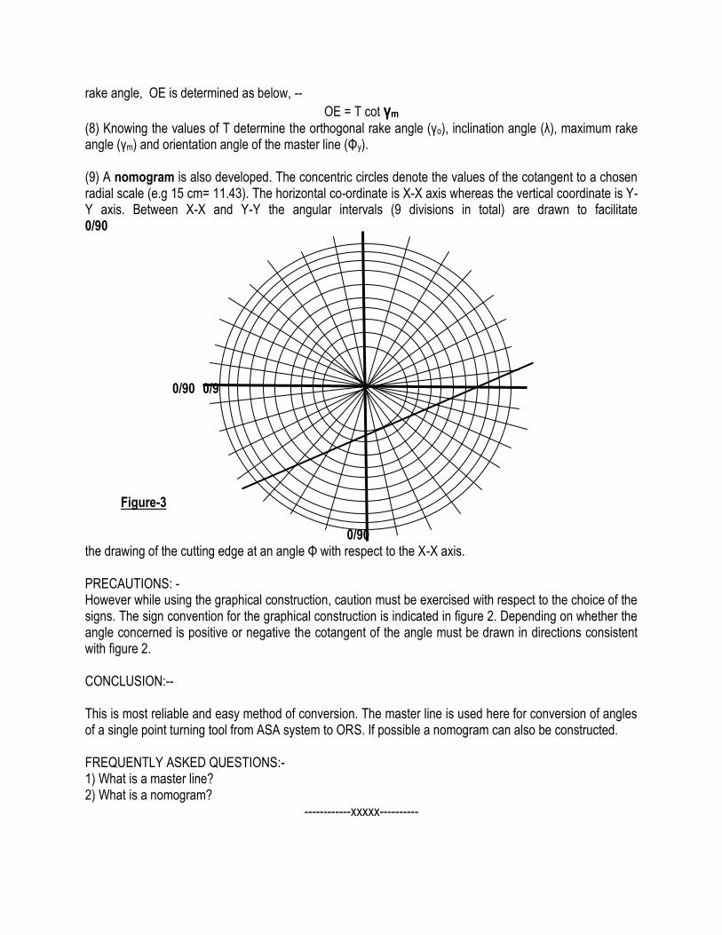
OE = T cot γm (8) Knowing the values of T determine the orthogonal rake angle (γo), inclination angle (λ), maximum rake angle (γm) and orientation angle of the master line (Φy). (9) A nomogram is also developed. The concentric circles denote the values of the cotangent to a chosen radial scale (e.g 15 cm= 11.43). The horizontal co-ordinate is X-X axis whereas the vertical coordinate is Y-Y axis. Between X-X and Y-Y the angular intervals (9 divisions in total) are drawn to facilitate 0/90 0/90 0/90 Figure-3 0/90 the drawing of the cutting edge at an angle Φ with respect to the X-X axis. PRECAUTIONS: - However while using the graphical construction, caution must be exercised with respect to the choice of the signs. The sign convention for the graphical construction is indicated in figure 2. Depending on whether the angle concerned is positive or negative the cotangent of the angle must be drawn in directions consistent with figure 2. CONCLUSION:-- This is most reliable and easy method of conversion. The master line is used here for conversion of angles of a single point turning tool from ASA system to ORS. If possible a nomogram can also be constructed. FREQUENTLY ASKED QUESTIONS:- 1) What is a master line? 2) What is a nomogram?
------------xxxxx----------