department of the army technical manual direct …
TRANSCRIPT

TM 9-1240-311-34
DEPARTMENT OF THE ARMY TECHNICAL MANUAL
DIRECT SUPPORT AND GENERAL SUPPORTMAINTENANCE MANUAL
FORTELESCOPE, ARTICULATED: M127 (1240-437-1254)
AND M127A1 (M127E1) (1240-148-8539) ANDHANGER ASSEMBLY (1240-906-79451
This copy is a reprint which includes currentpages from Change 1
This publication is a courtesy quick copy fromthe UNITED STATES ARMY ADJUTANTGENERAL PUBLICATIONS CENTER, ST. LOUIS,MISSOURI, to meet your needs while we arereplenishing our regular stock.
HEADQUARTERS, DEPARTMENT OF THE ARMYJUNE 1972

*TM 9-1240-311-34
TECHNICAL MANUAL HEADQUARTERSDEPARTMENT OF THE ARMY
No. 9-1240-311-34 WASHINGTON, D.C. 13 June 1972
Direct Support and General Support Maintenance ManualTELESCOPE, ARTICULATED: M127 (1240-437-1254), M127A1 (M127E1)
(1240-148-8539) AND HANGER ASSEMBLY (1240-906-7945)
Paragraph PageList of Illustrations ..................................................................................................................................................... ii
CHAPTER 1. INTRODUCTIONSection I. General............................................................................ 1-1 1-1
II. Description and data ....................................................... 1-3 1-1
CHAPTER 2. DIRECT SUPPORT AND GENERAL SUPPORT MAINTENANCEINSTRUCTIONS
Section I. Repair parts, special tools and equipment ...................... 2-1 2-1II. Troubleshooting............................................................... 2-3 2-1III. General Maintenance -.................................................... 2-5 2-2
CHAPTER 3. REPAIR INSTRUCTIONSSection I. General............................................................................ 3-1 3-1
II. Repair of telescope ......................................................... 3-3 3-1
CHAPTER 4. MAINTENANCE OF MATERIEL USED IN CONJUNCTION WITHTELESCOPE M127 AND M127A1 (M127E1)
Section I. Description ...................................................................... 4-1 4-1II. Maintenance of hanger assembly .................................. . 4-2 4-1
CHAPTER 5. FINAL INSPECTION ...................................................... . 5-1 5-1
APPENDIX A. REFERENCES................................................................ A-1 A-1
Index.......................................................................................................................................................................Index-1
*This manual, together with TM 9-1240-311-34P, 16 November 1971, and DMWR 9-1240-311, December 1969,supersedes TM 9-1240-311-35, 25 April 1966 in its entirety.
Change 1 i
}

TM 9-1240-311-34
LIST OF ILLUSTRATIONS
Number Title Page
1-1 Articulated telescope M127 and M127A1 (M127E1) with hanger assembly-assembled view.................. 1-2
3-1 Eyeguard. headrest. and bracket assembly-partial exploded view ......................................................... 3-2
3-2 Headrest and bracket assembly-exploded view........................................................................................ 3-3
3-3 Eyepiece assembly. diopter knob, and reticle projector-partial exploded view........................................ 3-4
3-4 Diopter knob assembly-exploded view...................................................................................................... 3-5
3-5 Conventional boresight control housing assembly-partial exploded view ................................................. 3-7
3-6 Conventional reticle lampholder assembly-partial exploded view ........................................................... 3-8
3-7 Deflection and elevation boresight housing assembly-partial exploded view............................................ 3-10
3-8 Horizontal or verticle boresight control dial and reticle missile lamp assembly-partial exploded view...... 3-12
3-9 Reticle missile lamp assembly-partial exploded view................................................................................ 3-10
3-10 Receptacle assembly wiring diagram ...................................................................................................... 3-13
3-11 Reticle projector charging valve and receptacle assembly-partial exploded view ................................... 3-14
3-12 Objective tube assembly, filter assembly, and filter assembly operating mechanism-partial.................... 3-15exploded view
3-13 Parallax adjustment mechanism-partial exploded view ............................................................................ 3-17
4-1 Hanger assembly-exploded view............................................................................................................... 4-2
Change 1 ii

TM 9-1240-311-34
CHAPTER 1
INTRODUCTION
Section I. GENERAL
1-1. Scopea. This publication contains instructions for repair of
articulated telescope M127, M127A1 (M127E1) andassociated equipment, by direct support (DS) andgeneral support (GS) maintenance shops.
b. Instructions for operation, lubrication, andpreventative maintenance of this instrument at theoperator and organizational levels are contained in TM 9-2350-230-12.
1-2. Forms and Reportsa. Maintenance Forms and Records. Maintenance
forms, records, and reports which are to be used bymaintenance personnel at all maintenance levels arelisted and prescribed by TM 38-750.
b. Reporting of Errors. The reporting of errors,omissions, and recommendations for improving thispublication by the individual user is encouraged.Reports should be submitted on DA Form 2028(Recommended Changes to Publications) and forwardeddirectly to the Commanding Officer, Frankford Arsenal,ATTN: SARFA-W3100, Philadelphia.PA 19137.
Section II. DESCRIPTION AND DATA
1-3. Description (Fig. 1-1)
a. Articulated telescope M127 and M127A1(M127E1) (fig. 1-1) are hermetically sealed, dual power,instrument used for direct fire control of the conventional(152MM) round and part of the guidance and controlgroup for the Shillelagh missile, the main armamentsystem of the armored reconnaissance airborne assaultvehicle, M551. The telescope is supported in the vehicleby telescope mount M149, and hanger assembly (8)described in Chapter 4. The articulated joints (4 and 10)permits the gunner to view the target through the fullrange of gun elevation and depression.
b. The filter selector lever (3) is used to select oneof two filters, or a clear glass plate, as required. Thedual power unit (6) contains an optical assembly which isplaced into the field-of-view by means of a selector leverto increase magnification of the telescope from 8 to 12power. A diopter adjustment knob (9) permits focusingof the telescope to the eye of the observer. Parallax iscorrected by rotating the parallax adjustment (a slottedscrew (5)) on top of the filter housing at the articulatedjoint. The reticle projector assembly (11) is separatelyhoused on the underside of the telescope in front of thearticulated joint. The assembly induces two reticlepatterns, one for the guided missile the other for theconventional round. separately into the field-of-view by
means of optical projection. Selection of reticles is madeby actuating a switch (gunner’s control panel) toilluminate either reticle pattern.
1-4. Dataa. General.
Length ............................................... 41-1/4 in.Weight ............................................... 33 lbsElectrical power source..................... 24-28 VDC
b. Operating Limits.Elevation ........................................... 20 degreesDepression ........................................ 10 degrees
c. Characteristics.Magnification ..................................... 3 or 12 power.......................................................... 8 power -8.0
degreesField-of-view...................................... 12 power -5.338.......................................................... degreesClear eye distance ............................ 1.31 in.Diameter of exit pupil ........................ 8 power -7MM
12 power -4.7MMEffective focal length of objective...... 12.00 in.Diopter range .................................... ±4 diopters
Change 1 1-1

TM 9-1240-311-34
Figure 1-1. Articulated telescope M127 and M127A1 (M127E1) with hanger assembly--assembled view.
Change 1 1-2

1-Objective tube assembly 5-Parallax adjustment 9-Diopter adjustment knob2-Filter housing assembly 6-Dual power assembly 10-Articulated joint-mechanical3-Filter selector lever 7-Eyepiece assembly 11-Reticle projector assembly4-Porro prism housing (articulated 8-Hanger assembly
joint-optical)
Figure 1-1-Continued.
1-3

TM 9-1240-311-34
CHAPTER 2
DIRECT SUPPORT AND GENERAL SUPPORT MAINTENANCEINSTRUCTIONS
Section I. REPAIR PARTS, SPECIAL TOOLS AND EQUIPMENT
2-1. Special Tools and EquipmentSpecial tools and equipment necessary to performoperations described in this manual are listed in table 2-1. Special tool sets of a general nature are authorized byTA and TOE.
2-2. Direct Support and General SupportMaintenance
Repair Parts Repair parts are listed and illustrated in TM9-1240311-34P. Maintenance instructions containedherein pertain only to replacement of repair partsauthorized at the direct support and general supportmaintenance levels.
Table 2-1. Special Tools and Equipment
ReferenceItem FSN or Fig. Para. Use
Part No. No. No.sAdapter, Sealing 8-32 UNC-2 4930-107-4378 3-15b Used with gun, sealing 4931-764-8134Dioptometer 4931-536-5557 3-7g To make optical checks when removing
parallax and adjusting for sharp eyepiecefocus.
Gun Sealing Hydraulic 4931-764-8134 5-3b Used with adapter 4930-107-4378 to injectsealing compound.
Wrench, Spanner, Adjustable, 5120-595-8996 3-16 Used to remove and replace screws 8590832Pin Type and 8624629, retainer 10533426, and studs
3-17 8624623 and 8624624.3-19
Section II. TROUBLESHOOTING
2-3. GeneralTroubleshooting is a systematic means of determining bysymptoms, malfunctions within the instrument.Adherence to procedures covered herein will materiallyreduce the time required to locate trouble and restore theinstrument to normal operation.
Troubleshooting performed by lower levels ofmaintenance are listed in TM 9-2350-230-12.
2-4. ProcedureTable 2-2 lists troubleshooting peculiar to direct supportand general support maintenance levels.
Table 2-2. Troubleshooting
Malfunction Probable Cause Corrective Action
Headrest is not held in secured positionwhen placed in bracket.
a. Plunger not securing headrest. a. Replace spring (9, fig. 3-2).Para 3-4.
b. Support on headrest not alined with plunger. b. Check support (4, fig. 3-2),straight en if bent
Change 1 2-1

TM 9-1240-311-34
Table 2-2. Troubleshooting--Continued
Malfunction Probable Cause Corrective Action
Image not clear or out of focus. a. Dirt on entrance or exit optics. a. Clean surfaces of optics.b. Diopter knob not adjusted to cover b. Adjust knob. Para 3-7a and g.
a minimum span of +4.00 to-4.00 diopters.
Reticle lamps fail to illuminate. a. Defective contact or loose wire. a. Check wire connection or replacecontact (9, fig. 3-6). Para 3-10.
b. Lack of electrical power to reticle b. Check electrical input into recep-projector. tacle assembly (9, fig. 3-11).
Para 3-20.c. Lamps burned out. c. Replace lamps (1, figs. 3-6 and 3-9).d. Loose wire connections or defective d. Check connection to receptacle as-
receptacle assembly. sembly (9, fig. 3-11) or replace.Para 3-14.
Telescope or reticle projector will not Dirt preventing valve from closing or Clean or replace valve stem. Para 3-6.hold nitrogen charge. faulty valve.
Filters not fully positioned in optical pathwhen viewed through eyepiece
a. Gear teeth on filter assembly housingbroken.
a. Replace filter assembly (10, fig. 3-12).Para 3-17.
assembly. b. Operating mechanism not adjusted b. Reposition gear (12, fig. 3-12) toproperly. mesh with gear at rear of the
filter assembly housing. Operatehandle to turn filter assembly toextreme position in both directionsand adjust stops (set-screws) (1,and 2, fig. 3-13). Para 3-18.
Excessive parallax between target andreticle.
Optical misalinement Use parallax adjustment screw (5, fig. 3-13) to-correct image. Para 5-4.
Section III. GENERAL MAINTENANCE
2-5. General Maintenance Procedures
Refer to TM 9-254.
2-6. Other Materials Required
The following materials are used to perform repairfunctions described in this manual.
Item Name Specification FSCGrease, Aircraft and Instrument MIL-G-23827 9150
Gear and Actuator ScrewGrease, Pneumatic Systems MIL-G-4343 9150Sealing Compound (Adhesive Cur- MIL-S-11031 8003ing)Sealing Compound (Noncuring) MIL-S-11030 8030
2-2

CHAPTER 3
REPAIR INSTRUCTIONS
Section I. GENERAL
3-1. Scope
This chapter contains detailed instructions, for repairof the telescope at the direct support and generalsupport maintenance levels. Disassembly of theinstrument and the extent of repair is limited toreplacement of parts authorized to the applicablemaintenance levels in TM 9-1240-31134P.
3-2. Parts Replacement
In subsequent paragraphs it is understood thatdamaged or missing parts are to be replaced. Suchrepair, if beyond the scope of this manual, shall be causeto evacuate the instrument to a depot maintenance shop.
Section II. REPAIR OF TELESCOPE
3-3. Replacement of Eyeguard (Fig. 3-1)
a. Removal. Remove three setscrews (1).Carefully pull eyeguard (2) from end of the eyepieceassembly.
b. Inspection. Inspect the rubber of the eyeguardfor cracks or other signs of deterioration.
c. Repair. Repair is limited to replacement of theeyeguard.
d. Installation. Install in reverse order ofdisassembly.
3-4. Replacement of Headrest and Repair ofBracket Assembly (Figs. 3-1 and 3-2)
a. Removal (Fig. 3-1).(1) Remove items 3, 4, and 5.(2) Carefully work headrest and bracket
assembly (6) along the neck of the eyepiece assemblyuntil removed.
b. Disassembly (Fig. 3-2).(1) Disengage appropriate screw (7) at top of
bracket assembly (6) to release headrest (1).(2) Remove items 2 and 3, and support (4)
from headrest (5).(3) Use screwdriver to remove screw (7).(4) Pull plungers (8) from both sides of
bracket (10) and remove spring (9).
c. Inspection.(1) Inspect the general condition of the
headrest, check for signs of deteriorating rubber.(2) Inspect hardware and items removed from
bracket for rust or corrosion or broken threads. Checkspring for compression.
d. Service. Clean the headrest in warm water witha mild soap. Dry thoroughly.
e. Repair. Repair is limited to replacement ofmissing, defective, or damaged parts.
f. Assembly (Fig. 3-2).(1) Apply a light film of grease, MIL-;23827, to
the cavity of plungers (8) and seat spring (9) into thecavity of one plunger.
(2) Insert plunger and spring through hole inside of bracket (10) and into the horizontal channel.Insert the second plunger through hole on opposite sideof bracket until the free end of spring is seated in cavityof the plunger.
(3) Apply sealing compound, MIL-S-11031, tothe threads of screw (7). Insert the screws through theelongated holes in top of the bracket and into thethreaded holes of the plungers.
(4) Position support (4) on the metal supportat rear of headrest (5), install washer (3), secure withscrew (2).
g. Installation (Fig. 3-1).
3-1

Figure 3-1. Eyeguard, headrest basket assembly-partial exploded view.
3-2

1-Setscrew, 6-32 x 1/8 (3) 3-Screw, 10-24 x 1/2, MS16995-36 5-Washer, flat 7/32 id, 221432MS51021-21 4-Washer, lock, No. 10, MS35333-73 6-Headrest and bracket assembly
2-Eyeguard, 10549867Figure 3-1-Continued.
(1) Guide bracket assembly (6) over theeyeguard and position on neck of the eyepieceassembly. Install items 5 and 4, secure with item 3.
(2) Install headrest (1, fig. 3-2) into eitherpositioning hole in bracket assembly for convenience ofthe operator.
3-5. Replacement of Eyepiece Assembly(Fig. 3-3)
Note: Remove headrest and bracket assembly
before removing eyepiece assembly. Refer toparagraphs 3-4 a and g.
a. Removal.(1) Remove item 1. Unscrew eyepiece
assembly (2) and remove from housing.(2) Reach into housing and remove packing
(3).
b. Inspection.(1) Inspect the eyepiece assembly. Check
1-Headrest2-Screw, 1/4-28 x 3/8, (2)
MS51958-773-Washer, lock 1/4 scr size, (2)
MS35338139
4-Support, 117309015-Headrest, padded, 105534766-Bracket assembly, 86245627-Screw, 8-36 x 1-1/8, (2) 86246768-Plunger (2), 8624675
9-Spring, compression, 15 coils,862453677
10-Bracket, 8624535
Figure 3-2. Headrest and bracket assembly exploded view.
3-3

for broken optics, worn, or broken threads on outersurface of the cell
(2) Check packing for cracks or other signs ofdeterioration.
c. Service.(1) Clean exposed surfaces of optics in the
eyepiece assembly with lens tissue paper. Do notdisassemble to clean.
1-Setscrew, 8-32 x 318, MS51021-342-Eyepiece assembly, 86245533-Packing, 2.612 id, 8624710-34-Cap, valve 820005565-Valve, air check, MS51877-26-Strap, 105165677-Valve stem, MS51607-1
8-Screw, 6-32 x 5/16 (4),MS51957-27
9-Washer, lock No. 86 (4),MS35333-71
10-Packing, 0.612 id. 8624710-111-Knob assembly, 8624555
12 -Scr, 1/4-20 z 7/8 (4),MS24674-25
13-Washer, lock, 1/4 scr size (4),MS3r5333.-74
14-Packing, 2.48 id, 8624711-215-Reticle projector assembly
8624501
Figure 3-3. Eyepiece assembly, diopter knob, and reticle projector--exploded view.
3-4
(2) Clean packing in warm water with a mildsoap. Dry thoroughly.
d. Repair. Repair is limited to replacement of theeyepiece assembly, packing, or hardware.
e. Installation.(1) Apply a light film of grease, MILG-4343, to
packing (3) and install into groove on inside wall of thehousing.
(2) Install eyepiece assembly (2) into thehousing. Secure with setscrew (1). Apply sealingcompound, MIL-S-11031, over head of setscrew.
3-6. Replacement of Purging and Charging ValveAssemblies (Figs. 3-3 and 3-11)
a. Removal. Remove the valve assembly fromtelescope eyepiece housing (fig. 3-3) or from the mainhousing of reticle projector assembly (fig. 3-11).
b. Disassembly. Disassemble items 4, 5, and 6
(fig. 3-3) or items 1, 2, and 3 (fig. 3-11) from respectivevalve stems (7, fig. 3-3 or 4, fig. 3-11).
c. Inspection. Inspect parts of the Valve assemblyfor wear, deterioration, and worn or broken threads.
d. Repair. Repair is limited to replacement of anydefective or missing part.
e. Assembly. Assemble items in reverse order ofdisassembly.
f. Installation. Apply sealing compound, MIL-S-11031, to threads of the valve stem and secure inposition.
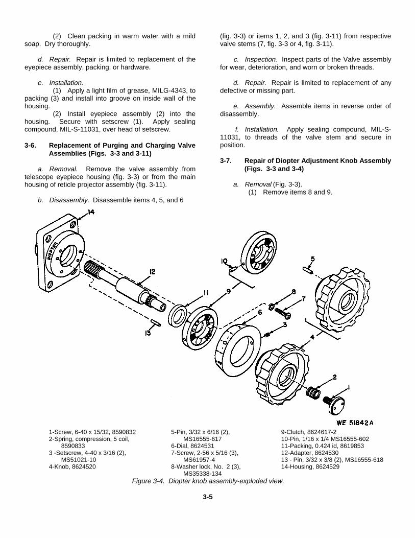
3-7. Repair of Diopter Adjustment Knob Assembly(Figs. 3-3 and 3-4)
a. Removal (Fig. 3-3).(1) Remove items 8 and 9.
1-Screw, 6-40 x 15/32, 8590832 5-Pin, 3/32 x 6/16 (2), 9-Clutch, 8624617-22-Spring, compression, 5 coil, MS16555-617 10-Pin, 1/16 x 1/4 MS16555-602
8590833 6-Dial, 8624531 11-Packing, 0.424 id, 86198533 -Setscrew, 4-40 x 3/16 (2), 7-Screw, 2-56 x 5/16 (3), 12-Adapter, 8624530
MS51021-10 MS61957-4 13 - Pin, 3/32 x 3/8 (2), MS16555-6184-Knob, 8624520 8-Washer lock, No. 2 (3), 14-Housing, 8624529
MS35338-134Figure 3-4. Diopter knob assembly-exploded view.
3-5

(2) Carefully pull knob assembly (11) fromhousing.
(3) Remove packing (10) from groove of knobassembly housing.
b. Disassembly (Fig. 3-4).(1) Remove items 1, 2, and 3.(2) Pull knob (4) and dial (6) from adapter
(12).(3) Remove items 7, 8, 9, 11, and 12 from
housing (14). Do not remove pins 5, 10, or 13 unlessdamaged.
c. Inspection.(1) Inspect the general condition of all parts.
Check for cracks, rust, corrosion or other forms ofdeterioration.
(2) Inspect hardware for worn or brokenthreads on screws.
(3) Inspect spring compression.(4) Inspect the dial, check legibility of
numbers and graduations.(5) Inspect the adapter, check teeth and
spline for nicks, burrs, or wear.(6) Inspect packing, check for wear or
deterioration.
d. Service.(1) Clean metal parts with a cloth moistened
with dry cleaning solvent.(2) Clean parts made of rubber, or other
synthetic material, in warm water with a mild soap. Drythoroughly.
e. Repair. Repair is limited to replacement ofdefective, damaged, or missing parts.
f. Assembly (Fig. 3-4).(1) Apply a light film of grease, MIL-G-23827,
to the largest diameter surface and to the spur gear ofadapter (12). Insert adapter into housing (14).
(2) Apply a light film of grease, MIL-G-4343,to all surfaces of packing (11). Position packing over theadapter and press into the housing cavity.
(3) Position clutch (9) over locator pins (13)and seat firmly on housing. Secure with washer (8) andscrew (7).
(4) Position dial (6) with the numeral "0” alinedwith the indicating line on clutch.
(5) Position knob (4) over dial. Graduallyposition knob until the two pins (5) are spaced an equaldistance from pin (10), extending into the inner
diameter of the clutch. Assure that serrations on theclutch and knob and teeth on spur gear and knob mate.Check alinement between dial and clutch. Secure dialwith screw (3).
(6) Install spring (2), secure with screw (1).
g. Installation (Fig. 3-3).(1) Apply a light film of grease; MIL-G-23827,
to the splined surface of adapter on knob assembly (11).(2) Apply a light film of grease, MIL-G-4343,
to all surfaces of packing (10) and install into groove ofthe knob assembly housing.
(3) Use an external power supply and apply24 VDC to pin "B" of receptacle assembly (9, fig. 3-11),ground on pin "C".
(4) Set objective tube of dioptometer to zero(0) diopters. Sight through dioptometer and adjust for asharp, clear reticle pattern.
(5) Place dioptometer against eyepieceassembly (2). Insert a wood stick, or other suitableobject, through hole in housing where knob assemblywas removed and make contact with teeth on side of thecell assembly.
(6) Observe through dioptometer while slidingthe cell assembly back and forth until the telescopereticle is at its sharpest point. Remove stick anddisconnect electrical source.
(7) Install knob assembly (11) into housing.Ensure the splines on adapter of knob assembly engageteeth on side of the cell assembly.Secure with washer (9) and screw (8).
(8) Check diopter movement of knobassembly. A minimum reading of +4.00 to -4.00diopters is required. If not obtained, remove anddisassemble the knob assembly using procedures inparagraphs b(1) and (2) above. Assemble usingprocedures in paragraphs f(4) through (6) above.
3-8. Replacement of Reticle Projector AssemblyPacking (Fig. 3-3)
a. Removal.(1) Remove items 12 and 13.(2) Carefully pry the reticle assembly (15)
from the filter housing.(3) Remove packing (14) from reticle
assembly housing.
b. Inspection. Inspect packing, check for wear ordeterioration.
c. Cleaning. Clean packing in warm water with amild soap. Dry thoroughly.
3-6

d. Installation.(1) Apply a thin film of grease, MIL-G-4343, to
all surfaces of packing (14).(2) Install packing into groove of the reticle
assembly housing.(3) Position reticle assembly (15) under the
filter housing, secure with washer (13) and screw (12).
3-9. Replacement of Deflection and ElevationBoresight Housing Packing (Fig. 3-5)
a. Disassembly.(1) Remove items 1 and 2.(2) Carefully separate control housing
assembly (3) from the main housing.(3) Peel packing (4) from groove of the control
housing. Do not remove locating pins (5) unlessdamaged.
b. Inspection. Inspect the packing, check for wearor deterioration.
c. Cleaning. Clean packing in warm water with amild soap. Dry thoroughly.
d. Repair. Repair is limited to replacement of thepacking and hardware.
e. Installation.(1) Apply a thin film of grease, MIL-G-4343, to
all surfaces of packing (4).(2) Install packing into groove of control
housing assembly (3).(3) Position locating pins on the control
housing assembly over locator holes in the mainhousing, push in until surfaces mate. Position washer(2), and secure with screw (1).
1 - Screw, 8-32 x 1/2, (6), 3 - Housing assembly, control, 4 - Packing, 3.875 id, 8624710-5MS5197-45 8624502 5 - Pin, 1/8 x 5/8, (2), MS16555-27
2 - Washer, lock No. 8, (6),MS35333-72
Figure 3-5. Conventional boresight control housing assembly-partial exploded view.
3-7

3-10. Replacement of Reticle Lamps and GroundStrap (Figs. 3-6 and 3-9)
a. Disassembly.(1) Twist to remove lampholder assembly (3.
fig. 3-6) with lamp attached. Push in and twist to removelamp (1).
(2) Unlock and open cover (fig. 3-9). Push inand twist lamp (1) to remove from lamp assembly.
(3) Detach hardware, items(2, 4 and 5, fig. 3-6), and remove strap (6).
(4) Remove screw (7, fig. 3-6), and washer(8). Pull contact assembly (9) out as far as possible fromthe support.
(5) Unsolder wire from contact and removethe assembly.
(6) Remove setscrew (10, fig. 3-6) and pullsupport (14) from housing.
(7) Remove screws (11, fig. 3-6 or 2, fig. 3-9)securing plate with mirror attached to support. Lift plateto remove.
(8) Press mirror (13, fig. 3-6 or 4, fig. 3-9)from plate (12, fig. 3-6 or 3, fig. 3-9).
b. Inspection.(1) Inspect lampholder assembly (3, fig. 3-6)
or lamp assembly (fig. 3-9), check for rust or corrosion.(2) Inspect ground strap; check for rust or
corrosion. Check soldered connections of terminals.(3) Inspect contact assembly; check for rust
or corrosion.(4) Inspect the mirror, if mirror is glass check
if broken, cracked, or chipped. If mirror is metal, cleanreflecting surface.
(5) Inspect plate and hardware; check for rust,worn, burred, or broken threads.
c. Repair. Repair is limited to replacement of allitems inspected in b above.
d. Assembly..(1) Apply sealing compound, MIL-S-11031, to
the inner flange of plate (12, fig. 3-6 or 3, fig. 3-9).(2) Press mirror (13, fig. 3-6 or 4, fig. 3-9) into
the plate opening with polished surface facing up. Wipeoff excess sealing compound.
(3) Position plate, with mirror installed, on therespective support. Apply sealing compound, MIL-S-11031, to threads of screws (11, fig. 3-6 or 2, fig. 3-9)and secure the plate.
1-Lamp, sgl cont, 28V, 8624583 6 - Strap, ground, 10549759 11 - Screw, 2-56 1/4, (S),2-Screw, 4-40 x 5/8, MS51957-18 7 - Screw, 4-40 x 1/4, MS51957-13 MS51959-33-Lampholder assembly, 10549783 8 - Washer, lock, No. 4, MS35333-70 12 - Plate, 86245874-Screw, 6 32 x 3/8, MS51957-28 9 - Contact assembly, 10549780 13 - Mirror, 117275795-Washer, lock No. 6, MS35333-71 10 - Setscrew, 6-32 x 3/16, (2), 14 - Support, 8624527
MS51029-17
Figure 3-6. Conventional reticle lampholder assembly-partial exploded view.
3-8

(4) Thread wire protruding from housingthrough side of support (14, fig. 3-6). Install support inhousing and apply sealing compound, MIL-S-11031, tothreads of setscrew (10); secure to housing.
(5) Solder wire to contact (9, fig. 3-6).Position contact on side of support and secure with items8 and 7.
(6) Position ground strap (6, fig. 3-6) betweenhousing and lampholder assembly (3), install items 5 and4. Apply sealing compound, MIL-S-11031, to screw (2)and secure the strap.
(7) Install lamp (1) in either the lampholderassembly (3, fig. 3-6) or lamp assembly (fig. 3-9).
3-11. Repair of Deflection or Elevation BoresightControl Assembly and Replace ment ofHousing Window (Fig. 3-7)
a. Disassembly.(1) Unscrew item 1 to remove item 2 and
pointer (3) from either knob assembly.(2) Remove items 4 through 8 and pull knob
(9) from spline of adapter.(3) Remove spacer (10) and stop (11).(4) Remove items 12 and 13, and pry clutch
(14) from locating pins.(5) Remove packing (15) from cavity of
adapter housing.(6) Unscrew item 16. Remove plate (17) and
window (18) from housing.
Note: Screw (19) is removed only to purge thereticle projector assembly.
b. Inspection.(1) Inspection the general condition of all
parts. Check for rust or corrosion.(2) Inspect dial, check legibility of letters,
numbers, and graduations.(3) Inspect spring for compression.(4) Inspect packing, check for wear or
deterioration of rubber.(5) Inspect hardware, check for burred or
stripped threads.
c. Cleaning.(1) Clean all metal parts with a cloth
moistened with dry cleaning fluid.(2) Clean the rubber packing in warm water
with a mild soap. Dry thoroughly.
d. Repair. Repair is limited to replacement of the ofthe pointer, clutch, packing window and hardware.
e. Assembly.(1) Position window (18) in insert of the housing.(2) Apply sealing compound, MIL-S-11031, to
threads of screws (16). Position plate (17) over windowand secure to housing with screws.
(3) Apply a thin film of grease, MIL-G-4343 topacking (15) and install into cavity of the adapterhousing.
(4) Apply a thin film of grease, MIL-G-23827, to thesplined surface of the adapter.
(5) Position clutch (14) over locating pins, installwashers (13) and secure with screws (12)
(6) Install stop (11) and spacer (10).(7) Position knob (9) over adapter. Push in until
serrations on clutch, knob, and spline mate.(8) Install spring (8) into center hole of the knob,
secure with screw (7)(9) Position dial (6) on flange of the knob, install
washer (5) and secure with nut (4)(10) Install pointer (3) in vertical position using the
inside holes of both knob assemblies Position washer(2), secure with screw (1)
3-12. Repair of Horizontal or Vertical BoresightControl Assembly (Fig. 3-8)
a. Removal. Remove items 1 and 2. Pull dial (4)from housing opening and remove packing (3) from insetof housing.
b. Disassembly(1) Remove items 5 and 6. Pull knob (7) from
end of adapter (9).(2) Disassemble items 8 through 11 and pry
plate (12) from locating pin (13). Do not remove pin.(3) Disassemble items 14 and 15. Remove
packing (16).
c. Inspection.(1) Inspect the general condition of all parts.
Check for rust or corrosion.(2) Inspect the spring for compression.(3) Inspect the packing, check for wear and
deterioration of rubber.(4) Inspect hardware, check for burred or
stripped threads.
d. Cleaning.
3-9

Figure 3-7. Deflection and elevation boresight housing assembly—partial exploded view.
3-10

1 - Screw. 6-32 x 3/8, (8), Dial, boresight deflection 13 - Washer. lock. No. 2, (6),MS51957-28 8624572-2 MS35338-n-134
2-Washer. lock. No. 6, (8), 7 - Screw, 6-40 x 3 /, (2), 8590832 14 - Clutch, (2), 8624617-1MS35333-71 8 - Spring. compression, 5 coils, (2), 15 - Packing. 0.424 id. (2). 86195853
3 - Pointer, (2). 8624618 8590833 16 - Screw, 2-56 x 1/4 (4,, MS519594 - Nut. 11/16-32. (2) 8624702. 9 - Knob, (2) 8624524 17 - Plate. 1.0 id. 86246455 - Washer. spring, 0.690( id, (2), 10 - Spacer. 0.937 id. (2), 8624704 18 - Window. 8624642
8624709 11 - Stop, (2). 8624714 19 - Screw, 4-40 x 5/32, 8626496 - Dial boresight elevation. 12 - Screw. 2-56 x 1/4, (6),
8624572-1 MS51957-3
Figure 3-7-Continued.
(1) Clean all metal parts with a clothmoistened with dry cleaning fluid.
(2) Clean rubber packing in warm water with amild soap. Dry thoroughly.
e. Repair. Repair is limited to replacement of thepacking, spring, and hardware.
f. Assembly.(1) Apply a thin film of grease, MIL-G-4343 to
packing (16) and insert into the groove of adapter (17).(2) Apply a thin film of grease, MIL-G-23827,
to the inner and outer surfaces of adapter (17) and installsetscrew (15) into the adapter.Screw in until the tip protrudes 3/16-inch on the verticaldial, or 3/4-inch on the horizontal dial.
(3) Install retainer (14) over setscrew andcheck length of screw tip. (See (2) above).
(4) Install plate (12) over locating pinprotruding from bottom of the retainer.
(5) Install items 11, 10, 9, and 8 on theadapter.
(6) Apply a thin film of grease, MIL-G-23827,to the entire surface of adapter (9). Position knob (7)over adapter. Push in until serrations on plate and knobmate.
(7) Install spring (6) into cavity of the knoband secure with screw (5).
g. Installation.(1) Apply a thin film of grease, MIL-G-4343, to
packing (3) and insert into groove of housing on dial (4).(2) Insert dial (4) through opening in housing.
Ensure that screw tip, (see para f(2)) is in contact withthe reticle assembly.
(3) Position washer (2), secure with screw (1).
3-13. Replacement of Reticle Missile LampAssembly (Fig. 3-8)
a. Removal.(1) Unscrew item 18. Remove washer (19)
and plate (20).
(2) Reach into housing opening and unsolderwire lead from receptacle assembly.
(3) Remove setscrew (21). Carefully pulllamp assembly (22) from housing.
b. Installation.(1) Position lamp assembly (22) into housing.
Ensure wire lead is free of obstacles and solder toreceptacle assembly.
(2) Install remaining parts in reverse order ofremoval. Apply sealing compound, MIL-S-11031, tothreads of setscrew (21).
3-14. Replacement of Receptacle Assembly (Fig. 3-11)
a. Removal.(1) Remove screw (18, fig. 3-8), washer (19),
and cover (20) from housing.(2) Reach into housing opening and unsolder
wire lead from pins "A" and "B" of receptacle assembly(9, fig. 3-11).
(3) Reach into housing and release receptacleground wire by removing items 5 and 6.
(4) Remove items 7 and 8. Pull receptacleassembly (9) from housing.
b. Inspection.(1) Inspect hardware, check for worn,
broken, or burred threads, rust or corrosion.(2) Inspect receptacle, check for broken or
cracked insulation, rust or corrosion. Check wire forfrayed, worn, or cracked insulation. Check solderedconnections between receptacle and terminal.
c. Repair Repair is limited to replacement of thereceptacle assembly. Wire attached to terminal "C" issupplied with receptacle.
d. Installation.(1) Install receptacle assembly (9) into
3-11

1 - Screw, 4-40 x 1/4, (2) 7 - Knob, vertical, 8624603-1 Setscrew, 5/16-14 x 1-7/16MS51957-13 Knob, horizontal, 8624603-2 horizontal), 8624681-2
2 - Washer, lock, No. 4, (2), 8 - Pin, 1/16 x 5/16, MS16555-603 16 - Packing, 0.239 id, 8624711-1MS35333-70 9 - Adapter, 6-40 x 0.687, 8624682 17 - Adapter, 8624600
3 - Packing, 0.489 id, 8624710-6 10 --Washer, key, 0.188 id. 8624602 18 - Screw, 4-40 x 1/4, (4),4 - Dial, boresight vertical, 8624567-1 11 --Washer, key, 0.188 id, 8624601 MS51957-13
Dial, boresight horizontal, 12 --Plate, serrated, 8624568 19 --Washer. lock, No. 4, (4),8624567-2 13 --Pin, 3/32 x 5/16, MS16555-617 MS35333-70
5 - Screw, 6-40 x 3/8, 8590832 14 --Retainer, 8624599 20 - Cover, 86246396 - Spring, compression, 5 coils, 15 --Setscrew, 5/16-14 x 7/8, (ver- 21 - Setscrew, 4-40 x 1/4, MS51029-60
8590833 tical), 8624681-1 22 - Lamp assembly, 8624519
Figure 3-8. Horizontal or vertical boresight control dial and reticle missile lamp assembly-partial exploded view.
3-12

1 - Lamp, sgl cont, 28V, 8624583 2 --Screw, 2-56 x 1/4, (3), 3-- Plate, 8624587MS51959-3 4-- Mirror, 11727579
Figure 3-9. Reticle missile lamp assembly-partial exploded view.
housing opening. Position washer (8) secure with screw(7).
(2) Position and solder wires to the receptacleassembly in accordance with wiring diagram (fig. 3-10).
Figure 3-10. Receptacle assembly wiring diagram
(3) Install remaining parts in reverse order ofremoval.
3-15. Removal of Objective Tube Assembly Fig. 3-12)
a. Disassembly. Remove items 2 and 3. Pry tubeassembly (4) from locating pin and lift from housing.
b. Assembly.(1) Position tube assembly (4) over locating
pin on filter housing, secure with items 3 and 2.(2) Remove eight screws (1), seven around
face of tube assembly and one on top surface.(3) Using adapter, attached to sealing gun.
inject sealing compound, MIL-S-11030, into the eightholes to affect a perfect seal between tube and housing.
(4) Install screws.
3-13

1 ---Cap, valve, 8200055 5 - Screw, 4-40 x 3/16, MS35212-11 8 - Washer. lock. No. 4 (4),2 - Air check valve. MS51377-2 6 - Washer, lock, No. 4, MS35333-87 MS35333-703 - Strap, 10516567 7 - Screw, 4-40 x 5/16 (4), 9 - Receptacle assembly, 86247214 - Valve stem, MS51607-1 MS651957-14
Figure 3-11. Reticle projector charging valve and receptacle assembly--partial exploded view.
3-16. Replacement of Filter Assembly PositioningPlunger and Spring (Fig. 3-12)
a. Disassembly.(1) Refer to paragraph 3-15 to remove and
replace the objective tube assembly.(2) Remove item 5.(3) Use adjustable spanner wrench to remove
item 6.(4) Remove spring (7) and plunger (8).
b. Inspection.(1) Inspect screws for broken or worn
threads, rust or corrosion.
(2) Inspect spring, check for compression.(3) Inspect plunger assembly, check bearing
for free rotation, rust or corrosion.
c. Cleaning. Clean all parts with a cloth moistenedwith dry cleaning solvent.
d. Repair. Repair is limited to replacement of thescrews and spring.
e. Assembly.(1) Apply a thin film of grease, MIL-G-23827,
to the bearing of plunger assembly (8). Insert spring (7)into hole of the plunger assembly and install items intohousing.
3-14

1 - Setscrew, 9-32 x 1/3, (8), 3 - Washer, lock, No. 6, (10), 6 - Screw, 5/16-18 x 0.18, P624629 9 - Stud, 8-32 x 0.95, 8624623MS51965-27 MS35333-71 7 - Spring, compression, 10 coils, 10--Filter assembly, 8624551
2 - Screw, 6-32 x 3/8, (10) 4 - Objective tube assembly, 8624516 8624625 11--Stud, 8624624MS51957-28 5 - Setscrew, 6-2 x 1/8, MS51021-21 8 - Plunger assembly, 8624561 12--Gear, 72 T, 8624578
Figure 3-12. Objective tube assembly, filter assembly and filter assembly operation mechanism—partial exploded view.
3-15
(2) Apply sealing compound, MIL-S-11031,to the threads of screw (6) anti install. Tighten screwuntil the plunger bearing seats into the groove on side offilter assembly (10) housing. Use the lever to rotate thefilter assembly. The plunger should permit rotation buthold the filter assembly in each position. Tighten orloosen screw as required.
(3) Install setscrew (5) and apply sealingcompound, MIL-S-11031. over head of the setscrew.
3-17. Replacement of Filter Assembly (Fig. 3-12).
a. Removal.(1) Refer to paragraph 3-15 for removal and
replacement of the objective tube assembly (4).(2) Use adjustable spanner wrench to remove
stud (9). Carefully pull filter assembly (10) from housing.
b. Inspection.(1) Inspect the filter assembly, check for
cracked or broken filters.(2) Inspect the stud, check for worn or broken
threads, rust or corrosion.(3) Inspect gear at rear of filter assembly
housing, check for broken or chipped teeth, rust, orcorrosion.
c. Cleaning.(1) Clean metal surfaces with a cloth
moistened with dry cleaning solvent.(2) Clean each filter using lens tissue paper.
d. Repair Repair is limited to replacement of thefilter assembly and stud.
e. Installation.(1) Apply grease, MIL-G-23827, to teeth of
gear at rear of the filter assembly housing and to theinside diameter of the mounting hole.
(2) Apply sealing compound, MIL-S-11031, tothe threads of stud (9). Position filter assembly (10),secure with the stud.
3-18. Repair of Filter Assembly OperatingMechanism (Figs. 3-12 and 3-13)
a. Disassembly.(1) Use adjustable spanner wrench to
unscrew stud (11, fig. 3-12). Remove gear (12).(2) Remove items 1 and 2, (fig. 3-13).
b. Inspection.
(1) Inspect hardware, check for broken orworn threads, rust or corrosion.
(2) Inspect gear, check for cracked, chippedor broken teeth, rust or corrosion.
c. Repair Repair is limited to replacement of wornor damaged parts.
d. Assembly.(1) Apply a thin film of grease, MIL-G-23827,
to the teeth of gear (12, fig. 3-12) and to the segmentgear installed in housing.
(2) Apply sealing compound, MIL-S-11031, tothreads of stud (11, fig. 3-12).
(3) Position gear to mesh properly with thesegment gear. Secure with the stud.
(4) Install setscrew (2, fig. 3-13) until the tipextends inside the housing. Setscrews act as stops tothe segment gear. Adjust setscrews to permit gear torun to the outer limits of the segment while maintainingmesh with gear (12).
(5) Apply a thin coat of sealing compound,MIL-S-11031, over head of setscrew and install setscrew(1, fig. 3-13) and again apply sealing compound, MIL-S-11031, over head of the setscrew.
3-19. Repair of Parallax Adjustment Mechanism(Fig. 3-13)
a. Disassembly.(1) Unscrew item 3. Use adjustable spanner
wrench to remove retainer (4).(2) Remove screw (5) and peel packing (6)
from groove of the screw.
b. Inspection.(1) Inspect hardware and retainer, check for
worn or broken threads, rust or corrosion.(2) Inspect packing, check for wear or
deterioration.
c. Cleaning.(1) Clean metal parts with a cloth moistened
with dry cleaning solvent.(2) Clean packing in warm water with a mild
soap. Dry thoroughly.
d. Repair. Repair is limited-to replacement of wornor damaged parts.
e. Assembly.(1) Apply a thin film of grease, MIL-G-4343, to
packing (6)and install in groove of screw (5).
3-16

1 - Setscrew, 8-32 x 3/16, (2), 4 - Retainer, 5/8-32 x 0.375 id,MS51029-26 10533426
2 - Setscrew, 8-32 x 3/8, (2), 5 - Screw, 1/4-28 x 1-1/4, 10533425MS51029-29 6 - Packing, 0.301 id, 8624710-8
3 - Setscrew, 6-32 x 1/8, MS51045-18
Figure 3-13. Parallax adjustment mechanism partial exploded view.
(2) Insert screw into the threaded hole of theshaft.
(3) Screw retainer (4) into housing until flushwith housing surface. Secure with setscrew (3).
3-20. Test and AdjustmentThe telescope will be checked for all necessary
electrical and mechanical functions that have beenaffected by repair or parts replacement. Use
an external 24VDC electrical source to energize: thelamp to illuminate the selected reticle.
3-21. Purging and ChargingPurging and charging will be performed following the
repair or replacement of an item that permits air to enterthe sealed telescope or reticle projector assembly.These units will be independently purged and charged inaccordance with procedures described in TM 750-116.
3-17

TM 9-1240-311-34
CHAPTER 4
MAINTENANCE OF MATERIEL USED IN CONJUNCTIONWITH TELESCOPE M127 AND M127A1 (M127E1)
Section I. DESCRIPTION
4-1. Hanger Assembly (8, Fig. 1-1)The hanger assembly 8570106 supports the eyepieceend of the telescope when installed in the vehicle. Thehanger is machined to form a precise fit on the coaxialmounting lug extending
from the eyepiece tube and attached at the other end,through a bearing, to a support bracket attached to thevehicle roof. The hanger assembly permits fullarticulation with nominal eyepiece displacement in avertical line.
Section II. MAINTENANCE OF HANGER ASSEMBLY
4-2. Inspectiona. Inspect the general condition of all parts.
b. Inspect bearing for binding, rough movement,rust or corrosion.
c. Inspect hardware for rust or corrosion.
4-3. Repair of Hanger Assembly (Fig. 4-1)a. Repair is limited to the replacement of the items
1 through 4.
b. Ring (4) is limited to replacement when removalof hanger assembly (5) from the turret roof is necessary.Refer to TM 9-2350-230-12, Figure 11-40.
Change 1 4-1

1 Pin cotter, 1/16 x 3/4, MS24665-1532 Washer, flat, 0.406 id. MS15795-8143 Pin, headed, 0.374 x 2-1/4, 105417504 Ring, 0.500 id MS16624-40505 Link 8570107
Figure 4-1. Hanger assembly--exploded view.
Change 1 4-2

CHAPTER 5
FINAL INSPECTION
5-1. GeneralFinal inspection is performed, after repair, to ensure
the telescope is serviceable according to establishedstandards and to certify the instrument for return to user.
5-2. DefinitionThe image will be sharp and clear at center of the field-of-view when checked with the aid of a dioptometer.
5-3. Eyepiece Focusa. Adjust eyepiece of dioptometer until the reticle is
sharp to the observer’s eye.
b. Set dioptometer scale to zero (0) diopter.
c. Position dioptometer against eyepiece of thetelescope and obtain a clear, sharp image of telescopereticle. The telescope diopter scale shall read zero (0)plus or minus 0.25 diopter when the target image is setat 1200 meters.
d. Sight through the eyepiece while rotating thediopter scale of the telescope to its clockwise stop andnote the indexed setting. Rotate the diopter scale to itscounterclockwise stop, and note the indexed setting.Eyepiece focus shall be adjustable over a minimumrange of plus to minus 4 diopters. If requirement cannotbe met, refer to paragraphs 3-7 a and g.
5-4. Parallaxa. Adjust diopter knob of telescope to obtain
sharpest focus of the conventional and missile reticles.The line-of-sight through each reticle
shall be directed at a target 1200 meters in distance.b. Observe reticle lines in relation to target image.
Any apparent movement of reticle lines when observer’shead is moved from side to side or up and down is theamount of parallax. Parallax for each reticle shall notexceed 0.2 mil at the 1200 meter setting, with parallaxadjustment screw (5, fig. 1-1) at midpoint of totalmechanical travel. Parallax of targets at 600 meters orinfinity shall not exceed 0.2 mil. Parallax between thetelescope reticles shall not exceed 0.2 mil.
5-5. Filter Transfer Lever
The filter level shall be operable and seat firmlyagainst the stops.
5-6. Optical Transfer Lever
The 8 to 12 power transfer lever shall be operableand seat firmly against the stops.
5-7. Lamp Housing Assemblies
The Lamp housing assemblies shall be mechanicallyoperable to permit replacement of either lamp.
5-8. Reticle Illumination
The lines of each illuminated reticle shall be brightand clearly defined when observed with filter in the clearposition. Any defect, in the form of a hole, crack, or chipappearing in the opaqued area of the reticle, shall not bebrighter than the reticle lines. Such defect shall because for rejection.
5-1

TM 9-1240-311-34
APPENDIX A
REFERENCES
1. Supply Publications
The following Department of the Army Supply Manuals pertain to repair of this material:Abrasive materials C5350IL-AFire Control Maintenance and Repair Shop Specialized Equipment Tool Set.
DS. GS. and Depot Maintenance. General Purpose Tools (4931-574-6433) SC 4931-95-CL-J51Fire Control Maintenance and Repair Shop Specialized Equipment Wrench
Set. Spanner DS. GS, and Depot Maintenance: Tubr, Dble-End ConcaveInserted Blade: Set of 76 Wrenches (4931-580-0012) SC 4931-95-CL-J52
Miscellaneous Hardware C5340-IL-AShop Set, Instrument and Fire Control, Field Maintenance:
Basic Less Power (4931-754-0740) SC 4931-95-CL-A07Tool Kit. Fire Control Instrument Repairman (4931-947-8243) SC 4931-95-CY-A09
2. Other Publicationsa. General.
Accident Reporting and Records AR 385-40Army Maintenance Management System (TAMMS) TM 38-750Direct Support Maintenance Activities FM 29-23General Support Maintenance Activities FM 29-24
b. Maintenance.
Direct Support and General Support Maintenance Repair Parts and SpecialTools List (including Depot Maintenance Repair Parts) for TelescopeArticulated: M127 (1240-437-1254), M127A1 (M127E1) (1240-148-8539)and Telescope Articulated M119 (1240-762-9333) and Hanger Assembly(1240-906-7945) TM 9-1240-311-34P C1
General Maintenance Procedures for Fire Control Materiel TM 9-254Grease, Aircraft and Instrument Gear and Actuator Screw MIL-G-23827Grease, Pneumatic Systems MIL-G-4343Maintenance Assistance and Instruction Team (MAIT) Program AR 750-51Operator’s and Organizational Maintenance Manual: Armored Reconnaissance
Airborne Assault Vehicle, FT, 152MM, M551 TM 9-2350-230-12Organizational, Direct Support, General Support, and Depot Maintenance
Repair Parts and Special Tools Lists for Armored Reconnaissance-AirborneAssault Vehicle: FT, 152MM, M551 TM 9-2350-230-25P 2
Organizational Direct Support, and General Support, Maintenance Proceduresfor Purging and Charging of Fire Control Instruments TM 750-116
Sealing Compound (N on-Curing) MIL-S-11030Sealing Compound (Adhesive Curing) MIL-S-11031
c. Operations.Northern Operations FM 31-71Operation and Maintenance of Army Materiel in Cold Weather (0 to
-65o F). TM 9-207
Change 1 A-1

TM 9-1240-311-34
d. Shipment and Storage.Parts, Equipment and Tools for Army Material, Packaging and Packing of MIL-P-14232/P10553175
A-2

INDEX
Paragraph PageA
Adjustment-(See specific items)Appendix:
References.............................................. A-1Assembly (See specific items)
BBracket assembly (See headrest and
bracket assembly)
DData................................................... 1-4 1-1Definition............................................ 5-2 5-1Deflection or Elevation Boresight
Control Assembly:Assembly .................................... 3-11e 3-9Disassembly................................ 3-11a 3-9Inspection.................................... 3-11b 3-9Cleaning...................................... 3-11c 3-9Repair ......................................... 3-11d 3-9
Description:Telescope ................................... 1-3 1-1Hanger Assembly........................ 4-1 4-1Diopter Adjustment Knob Assembly:Assembly .................................... 3-7f 3-6Removal...................................... 3-7a 3-5Disassembly................................ 3-7b 3-6Inspection.................................... 3-7c 3-6Service ........................................ 3-7d 3-6Repair ........................................ . 3-7e 3-6Installation................................... 3-7g 3-6
Direct Support and General SupportRepair Parts ................................ 2-2 2-1
Disassembly-(See specific items)
EEyeguard:
Removal...................................... 3-3a 3-1Inspection.................................... 3-3b 3-1Repair ......................................... 3-3c 3-1Installation................................... 3-3d 3-1
Eyepiece assembly:Removal...................................... 3-5a 3-3Inspection.................................... 3-5b 3-3Service ........................................ 3-5c 3-4Installation................................... 3-5e 3-5
FFilter assembly:
Removal...................................... 3-17a 3-16Inspection.................................... 3-17b 3-16Cleaning...................................... 3-17c 3-16Repair ......................................... 3-17d 3-1 6Installation .................................. 3-17e 3-16
Filter assembly operating mechanism:
Paragraph PageAssembly ..................................... 3-18d 3-16Disassembly ................................ 3-18a 3-16Inspection .................................... 3-18b 3-16Repair .......................................... 3-18c 3-16
Filter assembly positioning plungerand spring:Assembly ..................................... 3-16e 3-14Disassembly ................................ 3-16a 3-14Inspection .................................... 3-16b 3-14Cleaning....................................... 3-16c 3-14Repair .......................................... 3-16d 3-14
Final inspection:General........................................ 5-1 5-1Definition.....................................- 5-2 5-1Eyepiece focus ............................ 5-3 5-1Parallax........................................ 5-4 5-1Filter transfer lever....................... 5-5 5-1Optical transfer lever ................... 5-6 5-1Lamp housing assemblies ........... 5-7 5-1Reticle illumination....................... 5-8 5-1
Forms and records............................. 1-2a 1-1
GGeneral maintenance:
Materials required ....................... 2-6 2-2Procedures .................................. 2-5 2-2
HHanger assembly:
Assembly ..................................... 4-3b 4-1Description................................... 4-1 4-1Inspection .................................... 4-2 4-1Disassembly ................................ 4-3a 4-1
Headrest and bracket assembly:Assembly ..................................... 3-4f 3-1Removal ...................................... 3-4a 3-1Disassembly ................................ 3-4b 3-1Inspection .................................... 3-4c 3-1Service......................................... 3-4d 3-1Repair .......................................... 3-4e 3-1Installation.................................... 3-4g 3-1
Horizontal or vertical boresight controlassembly:Assembly ..................................... 3-12f 3-11Removal ...................................... 3-12a 3-9Disassembly ................................ 3-12b 3-9Inspection .................................... 3-12c 3-9Cleaning....................................... 3-12d 3-9Repair .......................................... 3-12e 3-11Installation.................................... 3-12g 3-11
IIllumination, reticle ............................. 5-8 5-1Inspection (See specific item)Inspection, final (See final inspection)
Index-1

Paragraph PageInstructions, repair:
Scope.......................................... 3-1 3-1Parts replacement....................... 3-2 3-1
L
Lamps. Reticle.................................. 3-10 3-8Lampholder assemblies:
Assembly .................................... 3-10d 3-8Disassembly................................ 3-10a 3-8Inspection................................... . 3-10b 3-8Repair ......................................... 3-10c 3-8
Lampholder, missile reticle:Removal...................................... 3-13a 3-11Installation................................... 3-13b 3-11
Lever, transfer (See transfer lever)List, direct support and general support
repair parts.................................. 2-2 2-1List of illustrations.......................................... ii
O
Objective tube assembly:Assembly .................................... 3-15b 3-13Disassembly................................ 3-15a 3-13
P
Picking:Deflection and boresight housing 3-9 3-7
Parallax.............................................. 5-4 5-1Parallax adjustment mechanism:
Assembly .................................... 3-19e 3-16Disassembly............................... . 3-19a 3-16Inspection.................................... 3-19b 3-16Cleaning...................................... 3-19c 3-16Repair ........................................ - 3-19d 3-16
Purging and charging ........................ 3-21 3-17Purging and charging valve assemblies:
Assembly .................................... 3-6e 3-5Removal...................................... 3-6a 3-5Disassembly................................ 3-66 3-5Inspection.................................... 3-6c 3-5Repair ......................................... 3-6d 3-5Installation................................... 3-6f 3-5
Paragraph PageR
Receptacle assembly:Removal ...................................... 3-14n 3-11Inspection .................................... 3-14b 3-11Repair .......................................... 3-14e 3-11Installation.................................... 3-14d 3-11
Replacement (See specific items)Reporting of errors ............................. 1-2b 1-1Reticle illumination (See illumination,
reticle)Reticle Projector assembly:
Removal ...................................... 3-8a 3-6Inspection .................................... 3-8b 3-6Cleaning....................................... 3-8c 3-6Installation.................................... 3-8d 3-7
S
Scope:General........................................ 1-1 1-1Repair instructions....................... 3-1 3-1
Special tools and equipment.............. 2-1 2-1
T
Table:Special tools and equipment(table 2-1) .................................... 2-1 2-1Troubleshooting (table 2-2) ......... 2-4 2-1
Test and adjustment .......................... 3-20 3-17Transfer lever:
Filter............................................. 5-5 5-1Optical ......................................... 5-6 5-1
Troubleshooting:General........................................ 2-3 2-1
Table 2-2 ............................................ 2-4 2-1
V
Valve (assemblies) (See purging andcharging valve assemblies)
W
Window:Deflection or elevation boresightcontrol assembly housing ............ 3-11 3-9
Index-2

By Order of the Secretary of the Army:
W. C. WESTMORELAND,General, Limited States Army,
Official: Chief of Staff.VERNE L. BOWERS,Major General, United States Army,The Adjutant General.
Distribution:To be distributed in accordance with DA Form 12-41 (qty rqr block No. 150) direct and general support maintenance
requirements for Telescope, Articulated.
U.S. GOVERNMENT PRINTING OFFICE : 1985 O - 461-202 (11662)

TM 9-1240-311-34 ARTICULATED: M127 (1240-473-1254) AND HANGER ASSEMBLY (1240-906-7945)-1972


PIN: 026627-0000

This fine document...
Was brought to you by me:
Liberated Manuals -- free army and government manuals
Why do I do it? I am tired of sleazy CD-ROM sellers, who take publicly available information, slap “watermarks” and other junk on it, and sell it. Those masters of search engine manipulation make sure that their sites that sell free information, come up first in search engines. They did not create it... They did not even scan it... Why should they get your money? Why are not letting you give those free manuals to your friends?
I am setting this document FREE. This document was made by the US Government and is NOT protected by Copyright. Feel free to share, republish, sell and so on.
I am not asking you for donations, fees or handouts. If you can, please provide a link to liberatedmanuals.com, so that free manuals come up first in search engines:
<A HREF=http://www.liberatedmanuals.com/>Free Military and Government Manuals</A>
– SincerelyIgor Chudovhttp://igor.chudov.com/
– Chicago Machinery Movers