deploy hitachi unified compute platform select for · pdf file1 1 deploy hitachi unified...
TRANSCRIPT
May 7, 2014
By
Reference Architecture Guide
Deploy Hitachi Unified Compute Platform Select for VMware vSphere with Cisco Unified Computing System Using Hitachi Unified Storage VM and Hitachi NAS Platform in a Scalable Environment
Jay Chellappan
FeedbackHitachi Data Systems welcomes your feedback. Please share your thoughts by sending an email message to [email protected]. To assist the routing of this message, use the paper number in the subject and the title of this white paper in the text.
Table of ContentsSolution Overview........................ .......................................................................3
Key Solution Components..................................................................................5
Hardware Components......................... ....................................................5Software Components......................... .....................................................9
Solution Design........................ .........................................................................13
Infrastructure Cell for Compute Resources......................... ...................16Infrastructure Cell for Storage Resources......................... .....................22Infrastructure Cell for Hitachi NAS Platform Resources......................... 23Application Cell for Hitachi Unified Compute Platform Select Management...........................................................................................27Application Cell for VMware vSphere......................... ............................30Hitachi NAS Platform Infrastructure......................... ...............................34Scaling Using Expansion Cell for Compute Resources......................... .38Scaling Using Expansion Cell for Storage Resources......................... ...41
Engineering Validation......................................................................................42
Test Methodology......................... ..........................................................42Test Infrastructure...................................................................................42Test Load................................................................................................43Interoperability Verification......................... ............................................44High Availability/Resiliency Verification......................... .........................44VMware vStorage APIs for Array Integration (VAAI) Verification......................... .....................................................................45
Conclusion........................ .................................................................................46
1
1
Deploy Hitachi Unified Compute Platform Select for VMware vSphere with Cisco Unified Computing System Using Hitachi Unified Storage VM and Hitachi NAS Platform in a Scalable EnvironmentReference Architecture Guide
This reference architecture guide gives you guidance to deploy Hitachi Unified Compute Platform Select for VMware vSphere with Cisco Unified Computing System. This environment uses Hitachi NAS Platform 4060 and Hitachi Unified Storage VM.
This is advice on how to build a virtual infrastructure with the following primary design goals:
Availability
Scalability
Elasticity
manageability
The benefits of this solution include the following:
Faster deployment
Reduced risk
Predictability
Ability to scale out
Lower cost of ownership
2
2
The Hitachi Unified Compute Platform family has completely integrated and flexible solutions. Each solution is configured for immediate deployment to run top-tier infrastructure applications without over-purchasing or provisioning unnecessary equipment. Each custom-built-solution has its entire solution stack-certified. There are no known compatibility issues.
This reference architecture guide focuses on designing a virtual infrastructure capable of hosting virtual machines running general server application workloads. It is strongly recommended to run a server capacity-planning pilot to gather sizing and IOPS information before designing your environment.
You need familiarity with the use and configuration of the following to use this reference architecture guide:
Hitachi NAS Platform
Hitachi Unified Storage VM
Cisco Unified Computing System — Servers and Fabric Interconnects
Cisco Nexus Switches
Hitachi Dynamic Provisioning with Hitachi Storage Virtualization Operating System
VMware vSphere 5
Note — Testing of this configuration was in a lab environment. Many things affect production environments beyond prediction or duplication in a lab environment. Follow the recommended practice of conducting proof-of-concept testing for acceptable results in a non-production, isolated test environment that otherwise matches your production environment before your production implementation of this solution.
3
3
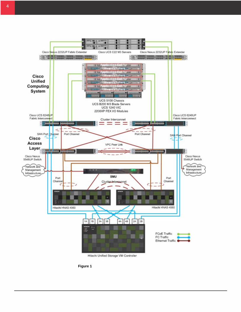
Solution OverviewThis reference architecture uses a VMware infrastructure supported by Cisco and Hitachi hardware to create a flexible and pre-validated end-to-end converged stack solution. This converged solution validates the integration of the hardware stack (compute, storage and networking) with the software stack (hypervisor and management for both software and hardware components).
The following components create Hitachi Unified Compute Platform Select for VMware vSphere with Cisco Unified Computing System using Hitachi Unified Storage VM environment:
Hitachi NAS Platform 4060 — Network-attached storage solution used for file sharing, file server consolidation, data protection, and business-critical NAS workloads
Hitachi Unified Storage VM — Storage virtualization system designed to manage storage assets more efficiently
Hitachi Dynamic Provisioning — Wide striping and thin provisioning for greater operational and storage efficiency
Cisco UCS Server — Enterprise-class performance, versatility, and density without compromise for virtual and bare-metal workloads
Cisco UCS 6248UP Fabric Interconnect Switch — A single, highly available management domain that supports all attached UCS Server chassis, server blades, and rack servers connectivity to the data center network
Cisco Nexus 5548UP Unified Switch — LAN and storage traffic consolidation to Hitachi Unified Storage VM
VMware vSphere 5 — Virtualization technology providing the infrastructure for the data center
Figure 1 on page 4 illustrates the high-level logical design of this reference architecture.
4
4
Figure 1
5
5
Key Solution ComponentsThese are descriptions of the key hardware and software components used to deploy this Hitachi Unified Compute Platform Select for VMware vSphere with Cisco Unified Computing System using Hitachi Unified Storage VM reference architecture.
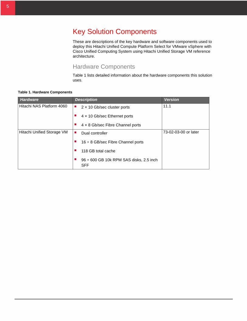
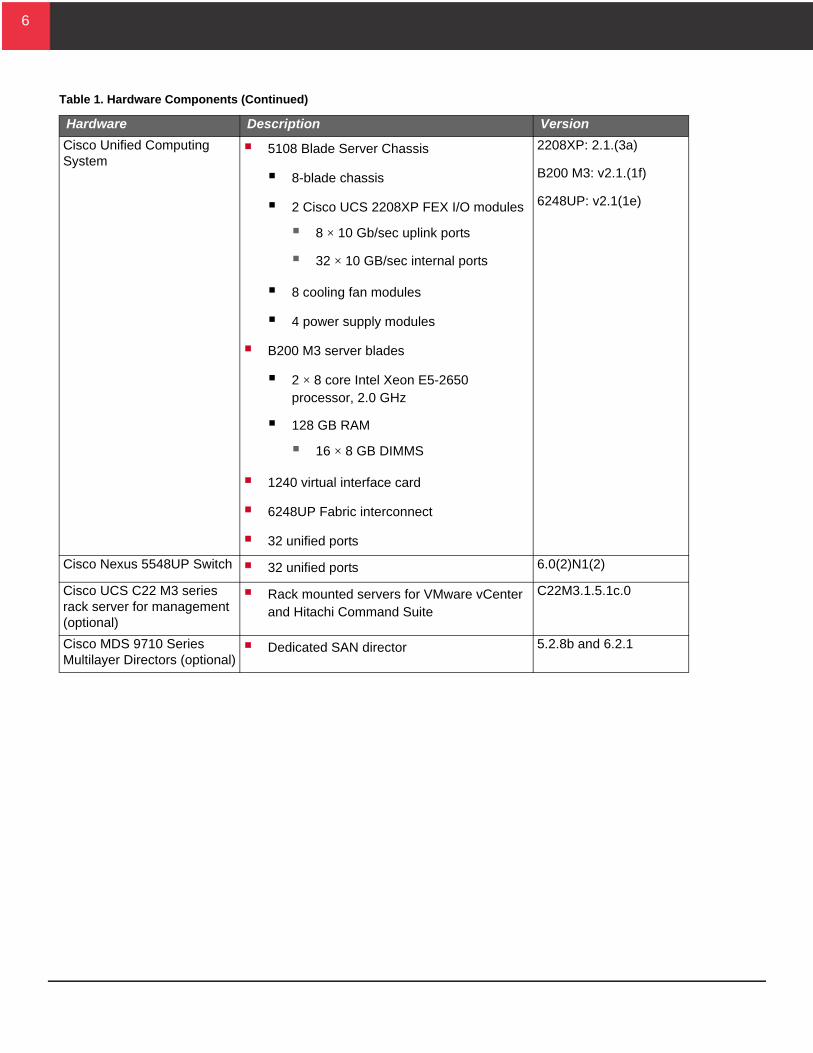
Hardware ComponentsTable 1 lists detailed information about the hardware components this solution uses.
Table 1. Hardware Components
Hardware Description Version
Hitachi NAS Platform 4060 2 × 10 Gb/sec cluster ports
4 × 10 Gb/sec Ethernet ports
4 × 8 Gb/sec Fibre Channel ports
11.1
Hitachi Unified Storage VM Dual controller
16 × 8 GB/sec Fibre Channel ports
118 GB total cache
96 × 600 GB 10k RPM SAS disks, 2.5 inch SFF
73-02-03-00 or later
6
6
Cisco Unified Computing System
5108 Blade Server Chassis
8-blade chassis
2 Cisco UCS 2208XP FEX I/O modules
8 × 10 Gb/sec uplink ports
32 × 10 GB/sec internal ports
8 cooling fan modules
4 power supply modules
B200 M3 server blades
2 × 8 core Intel Xeon E5-2650 processor, 2.0 GHz
128 GB RAM
16 × 8 GB DIMMS
1240 virtual interface card
6248UP Fabric interconnect
32 unified ports
2208XP: 2.1.(3a)
B200 M3: v2.1.(1f)
6248UP: v2.1(1e)
Cisco Nexus 5548UP Switch 32 unified ports 6.0(2)N1(2)
Cisco UCS C22 M3 series rack server for management (optional)
Rack mounted servers for VMware vCenter and Hitachi Command Suite
C22M3.1.5.1c.0
Cisco MDS 9710 Series Multilayer Directors (optional)
Dedicated SAN director 5.2.8b and 6.2.1
Table 1. Hardware Components (Continued)
Hardware Description Version
7
7
Hitachi NAS PlatformHitachi NAS Platform is an advanced and integrated network attached storage (NAS) solution. It provides a powerful set of tools for file sharing, file server consolidation, data protection, and business-critical NAS workloads.
Powerful hardware-accelerated file system with multiprotocol file services, dynamic provisioning, intelligent tiering, virtualization, and cloud infrastructure
Seamless integration with Hitachi SAN storage, Hitachi Command Suite, and Hitachi Data Discovery Suite for advanced search and index
Integration with Hitachi Content Platform for active archiving, regulatory compliance, and large object storage for cloud infrastructure
Take advantage of the following features for better management and tighter integration of your Hitachi NAS Platform environment with your VMware infrastructure.
Hitachi NAS Virtual Infrastructure Integrator — Simplify virtual machine backup, restoration, cloning, and NFS datastore management
Hitachi NAS Deduplication — Reclaim up to 90% of unstructured data storage capacity, to extend the life of existing storage assets
Hitachi Unified Storage VMHitachi Unified Storage VM is an entry-level enterprise storage platform from Hitachi Data Systems. It combines storage virtualization services with unified block, file, and object data management. This versatile, scalable platform offers a storage virtualization system to provide centralized storage services to existing storage assets.
Unified management delivers end-to-end central storage management of all virtualized internal and external storage on Unified Storage VM. A unique, hardware-accelerated, object-based file system supports intelligent file tiering and migration, as well as virtual NAS functionality, without compromising performance or scalability.
The benefits of Unified Storage VM are the following:
Enables the move to a new storage platform with less effort and cost when compared to the industry average
Increases performance and lowers operating cost with automated data placement
Supports scalable management for growing and complex storage environment while using fewer resources
8
8
Achieves better power efficiency and with more storage capacity for more sustainable data centers
Lowers operational risk and data loss exposure with data resilience solutions
Consolidates management with end-to-end virtualization to prevent virtual server sprawl
Cisco Unified Computing SystemCisco Unified Computing System is a data center platform that unites compute, network, storage access, and virtualization into a cohesive system. It is designed to reduce total cost of ownership and increase business agility.
The system integrates the following:
A low-latency, lossless 10 Gigabit Ethernet unified network fabric with enterprise-class, x86-architecture servers
A scalable, multi-chassis platform in which all resources participate in a unified management domain
Managed as a single system, whether there is one server or 160 servers with thousands of virtual machines. Unified Computing System decouples scale from complexity.
Unified Computing System accelerates the delivery of new services simply, reliably, and securely through end-to-end provisioning and migration support for virtualized and non-virtualized systems.
Cisco Unified Computing System consists of the following components:
Cisco UCS 6200 Series Fabric Interconnects
This is a family of line-rate, low-latency, lossless, 10 Gb/sec Ethernet and Fibre Channel over Ethernet interconnect switches. It provides the management and communication backbone for Unified Computing System. These Fabric interconnects support Cisco Virtual Machine Fabric Extender (VM-FEX) technology.
Cisco UCS 5100 Series Blade Server Chassis
This supports up to eight blade servers and up to two fabric extenders in a six rack unit enclosure.
Cisco UCS B-Series Blade Servers
Cisco UCS Adapters
Wire-once architecture offers options to converge the fabric, optimize virtualization, and simplify management. These adapters support Cisco Virtual Machine Fabric Extender (VM-FEX) technology.
9
9
Cisco UCS Manager
This provides unified, embedded management of all software and hardware components in Cisco Unified Computing System.
Other hardware used with Unified Computing System includes the following:
Cisco Nexus 5548UP Switch — This is a 1RU 10 Gigabit Ethernet, Fibre Channel, and FCoE switch. It offers up to 960 Gb/sec of throughput and up to 48 ports. The switch has the following:
32 unified ports
1 expansion slot supporting modules to connect with either or both of the following:
10 Gigabit Ethernet and FCoE ports
Fibre Channel SANs with 8/4/2/1 Gb/sec Fibre Channel switch ports
Cisco MDS 9700 Series Multilayer Directors (optional) — Meets the requirements of large, virtualized, data center storage environments. They provide availability, scalability, flexibility, security, ease of management, and transparent integration of new technologies.The optional dedicated SAN design is described in “Optional Dedicated SAN Design using Cisco MDS 9700 Series Multilayer Directors” on page 21.
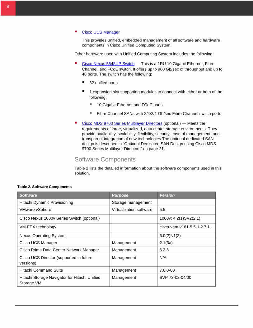
Software ComponentsTable 2 lists the detailed information about the software components used in this solution.
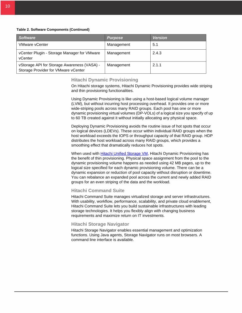
Table 2. Software Components
Software Purpose Version
Hitachi Dynamic Provisioning Storage management
VMware vSphere Virtualization software 5.5
Cisco Nexus 1000v Series Switch (optional) 1000v: 4.2(1)SV2(2.1)
VM-FEX technology cisco-vem-v161-5.5-1.2.7.1
Nexus Operating System 6.0(2)N1(2)
Cisco UCS Manager Management 2.1(3a)
Cisco Prime Data Center Network Manager Management 6.2.3
Cisco UCS Director (supported in future versions)
Management N/A
Hitachi Command Suite Management 7.6.0-00
Hitachi Storage Navigator for Hitachi Unified Storage VM
Management SVP 73-02-04/00
10
10
Hitachi Dynamic ProvisioningOn Hitachi storage systems, Hitachi Dynamic Provisioning provides wide striping and thin provisioning functionalities.
Using Dynamic Provisioning is like using a host-based logical volume manager (LVM), but without incurring host processing overhead. It provides one or more wide-striping pools across many RAID groups. Each pool has one or more dynamic provisioning virtual volumes (DP-VOLs) of a logical size you specify of up to 60 TB created against it without initially allocating any physical space.
Deploying Dynamic Provisioning avoids the routine issue of hot spots that occur on logical devices (LDEVs). These occur within individual RAID groups when the host workload exceeds the IOPS or throughput capacity of that RAID group. HDP distributes the host workload across many RAID groups, which provides a smoothing effect that dramatically reduces hot spots.
When used with Hitachi Unified Storage VM, Hitachi Dynamic Provisioning has the benefit of thin provisioning. Physical space assignment from the pool to the dynamic provisioning volume happens as needed using 42 MB pages, up to the logical size specified for each dynamic provisioning volume. There can be a dynamic expansion or reduction of pool capacity without disruption or downtime. You can rebalance an expanded pool across the current and newly added RAID groups for an even striping of the data and the workload.
Hitachi Command SuiteHitachi Command Suite manages virtualized storage and server infrastructures. With usability, workflow, performance, scalability, and private cloud enablement, Hitachi Command Suite lets you build sustainable infrastructures with leading storage technologies. It helps you flexibly align with changing business requirements and maximize return on IT investments.
Hitachi Storage NavigatorHitachi Storage Navigator enables essential management and optimization functions. Using Java agents, Storage Navigator runs on most browsers. A command line interface is available.
VMware vCenter Management 5.1
vCenter Plugin - Storage Manager for VMware vCenter
Management 2.4.3
vStorage API for Storage Awareness (VASA) - Storage Provider for VMware vCenter
Management 2.1.1
Table 2. Software Components (Continued)
Software Purpose Version
11
11
Use Storage Navigator for the following:
Pool creation and expansion
LUN creation and expansion
Online microcode updates and other system maintenance functions
Performance metrics
You need Storage Navigator to take advantage of the full features of Hitachi Unified Storage VM.
Cisco Nexus 1000v Series Switches (Optional)Cisco Nexus 1000V Series Switches provide a comprehensive and extensible architectural platform for virtual machine (VM) and cloud networking. The switches are designed to accelerate server virtualization and multi-tenant cloud deployments in a secure and operationally transparent manner. Integrated into the VMware vSphere hypervisor and fully compatible with VMware vCloud Director, the Cisco Nexus 1000V Series switches provide the following:
Advanced virtual machine networking based on Cisco NX-OS operating system and IEEE 802.1Q switching technology
Cisco vPath technology for efficient and optimized integration of virtual network services
Virtual extensible local area network (VXLAN) support for cloud networking
Hypervisor agnostic
Cisco UCS ManagerCisco UCS Manager provides unified, centralized, embedded management of all Cisco Unified Computing System software and hardware components across multiple chassis and thousands of virtual machines. Administrators use the software to manage the entire Cisco UCS as a single logical entity through an intuitive graphical user interface, a command-line interface, or an XML API.
Service profiles and templates support versatile role- and policy-based management. System configuration information can be exported to configuration management databases (CMDBs) to facilitate processes based on IT infrastructure library (ITIL) concepts.
Cisco Prime Data Center Network ManagerCisco Prime Data Center Network Manager (DCNM) is designed to help you efficiently implement and manage virtualized data centers. It includes a feature-rich, customizable dashboard that provides visibility and control through a single pane of glass to Cisco Nexus and MDS products.
12
12
Cisco UCS Director (Supported in a Future Version)Cisco UCS Director is a unified management solution that enhances the value of shared infrastructure solutions, which bring together compute, network, and storage resources. Together, Cisco UCS Director and shared infrastructures improve IT agility, protect investments, simplify deployment of new services, and optimize asset use.
VMware vSphere 5VMware vSphere 5 is a virtualization platform that provides a data center infrastructure. It features vSphere Distributed Resource Scheduler (DRS), high availability, and fault tolerance.
VMware vSphere 5 has the following components:
ESXi 5 — This is a hypervisor that loads directly on a physical server. It partitions one physical machine into many virtual machines that share hardware resources.
vCenter Server 5 — This allows management of the vSphere environment through a single user interface. With vCenter, there are features available such as vMotion, Storage vMotion, Storage Distributed Resource Scheduler, High Availability, and Fault Tolerance.
13
13
Solution DesignThis is the detailed design for the Hitachi Unified Compute Platform Select for VMware vSphere with Cisco Unified Computing System using Hitachi NAS Platform and Hitachi Unified Storage VM reference solution. It includes software and hardware design information required to build the basic infrastructure for the virtualized data center environment.
To provide you with options for scaling out your environment in modular increments, this solution uses a converged cell architecture. Converged infrastructure cells offer containers with the pre-defined elements necessary to configure, size and scale converged infrastructure solutions. Each cell defines the compute, network, and/or storage resources necessary to support a specific workload. Solutions can be designed, sized, and scaled using pre-defined cells, each designed for a different function:
Infrastructure cells
Application cells
Resource cells
Expansion cells
Converged infrastructure cells offer a more efficient, flexible, and granular approach to sizing and scaling converged solutions than the more common uniform building blocks.
This design defines compute and storage resource groups to support a specific usage scenario. You can add additional converged cells to scale out the environment to meet your organization's requirements.
14
14
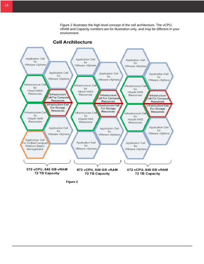
Figure 2 illustrates the high-level concept of the cell architecture. The vCPU, vRAM and Capacity numbers are for illustration only, and may be different in your environment.
Figure 2
15
15
The architecture consists of preconfigured cells designed to support general server workload. These cells provide the following:
Infrastructure cell for compute resources — Foundation for compute components
Infrastructure cell for storage resources — Foundation for storage components
Application cell for Hitachi Unified Compute Platform Select management — Resource to manage this environment
This cell is required only if an existing resource for managing a VMware vSphere environment does not exist.
Application cell for VMware vSphere — Provides the resource for hosting virtual machines running general server application workloads.
Expansion cell for compute resources — Provides the compute resources for scaling out the Unified Compute Platform Select for VMware vSphere environment.
Expansion cell for storage resources — Provides the storage resources for scaling out the Unified Compute Platform Select for VMware vSphere environment.
These cells provide the compute and storage hardware needed to build this scalable solution.
16
16
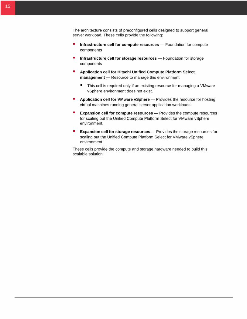
Infrastructure Cell for Compute ResourcesThe infrastructure cell for compute resources provides the foundation for the compute components needed to start building this solution.
Figure 3 shows the infrastructure cell for compute resources.
Figure 3
Use the infrastructure cell for compute resources in conjunction with the following cells:
Infrastructure cell for storage resources
Infrastructure cell for Hitachi NAS Platform resources
Application cell for Hitachi Unified Compute Platform Select management
Application cell for VMware vSphere
Expansion cell for compute resources
The infrastructure cell for compute resources, the infrastructure cell for storage resources and the infrastructure cell for Hitachi NAS Platform are the core infrastructure cells required to build a scalable solution. These three infrastructure cells support up to three expansion cells for Cisco UCS 5108 chassis before requiring new infrastructure cells. Every infrastructure cell for compute resources requires one infrastructure cell for storage resources.
17
17
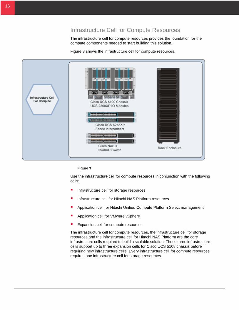
Table 3 shows the components of the infrastructure cell for compute.
The hardware in the infrastructure cell for compute resources makes up the core compute hardware in this solution.
Chassis ComponentsThe Cisco UCS 5108 Blade Server chassis has redundant management modules to provide high availability access to manage and monitor the chassis, switch modules, and server blades. The chassis contains redundant switch modules for high availability and maximum throughput. Hot-swappable power and fan modules allow for nondisruptive maintenance.
Network InfrastructureThe network design used in this solution provides ample bandwidth and redundancy for the following:
A fully populated infrastructure cell for compute resources
An infrastructure cell for storage resources
An infrastructure cell for Hitachi NAS Platform resources
Up to three expansion cells for compute resources
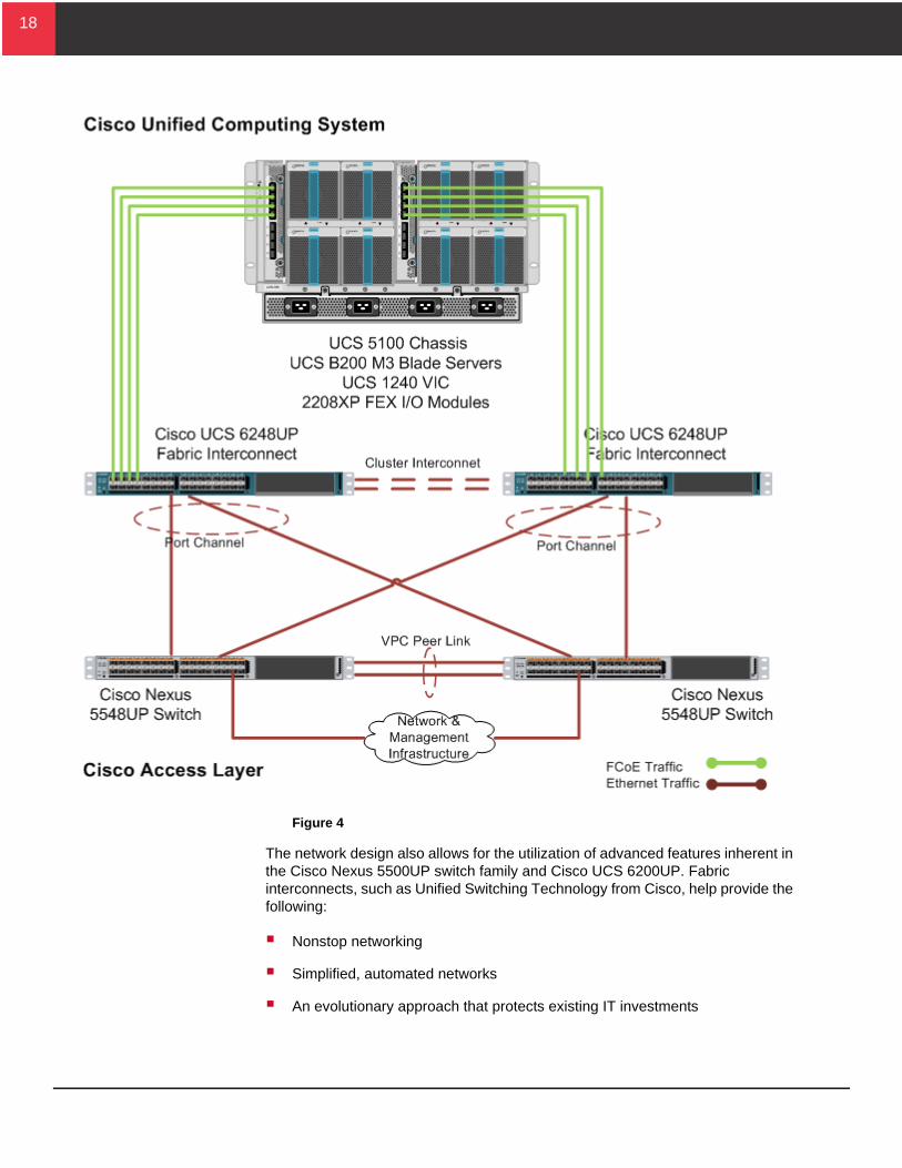
Figure 4 on page 18 shows the physical network configuration of the infrastructure cell for compute resources.
Table 3. Hardware Components for the Infrastructure Cell for Compute Resources
Hardware Description Version Quantity
Cisco Unified Computing System
Cisco UCS 5108 Chassis
8-blade chassis
2 × Cisco UCS 2208XP FEX I/O Modules with 8 × 10 Gb/sec uplink ports, 32 × 10 GB/sec Internal ports
8 Cooling fan modules
4 Power supply modules
2208XP: 2.1.(3a) 1
Cisco UCS 6248UP Fabric Interconnect Switch
32 Unified Ports 6248UP: v2.1(3a) 2
Cisco Nexus 5548UP Switch 32 Unified Ports 5548UP: 6.0(2)N1(2) 2
Cisco MDS 9700 Series Multilayer Directors (Optional)
Dedicated SAN Director 6.2.1 2
18
18
Figure 4
The network design also allows for the utilization of advanced features inherent in the Cisco Nexus 5500UP switch family and Cisco UCS 6200UP. Fabric interconnects, such as Unified Switching Technology from Cisco, help provide the following:
Nonstop networking
Simplified, automated networks
An evolutionary approach that protects existing IT investments
19
19
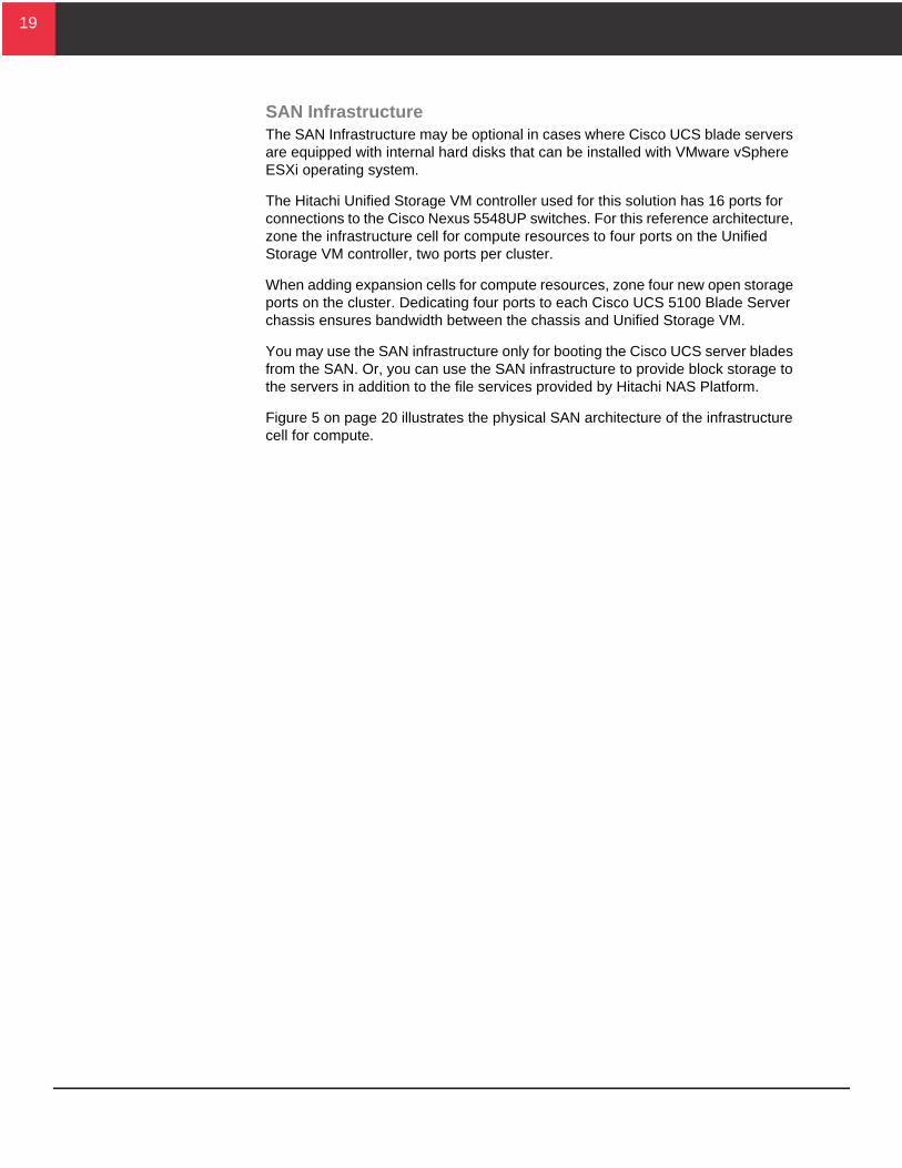
SAN InfrastructureThe SAN Infrastructure may be optional in cases where Cisco UCS blade servers are equipped with internal hard disks that can be installed with VMware vSphere ESXi operating system.
The Hitachi Unified Storage VM controller used for this solution has 16 ports for connections to the Cisco Nexus 5548UP switches. For this reference architecture, zone the infrastructure cell for compute resources to four ports on the Unified Storage VM controller, two ports per cluster.
When adding expansion cells for compute resources, zone four new open storage ports on the cluster. Dedicating four ports to each Cisco UCS 5100 Blade Server chassis ensures bandwidth between the chassis and Unified Storage VM.
You may use the SAN infrastructure only for booting the Cisco UCS server blades from the SAN. Or, you can use the SAN infrastructure to provide block storage to the servers in addition to the file services provided by Hitachi NAS Platform.
Figure 5 on page 20 illustrates the physical SAN architecture of the infrastructure cell for compute.
20
20
Figure 5
21
21
Optional Dedicated SAN Design using Cisco MDS 9700 Series Multi-layer DirectorsThe Cisco MDS 9700 directors may be used in a Hitachi Unified Compute Platform for VMWare vSphere solution that involves a dedicated SAN design. Access to Hitachi Unified Storage VM is provided by these MDS 9700 Fibre Channel directors.
Two distinct data paths further enhanced with independent vSAN definitions are created by attaching each of the NPV-enabled Cisco UCS 6248UP Fabric Interconnects to one of the MDS 9700 directors with a Fibre Channel port channel. Link fault tolerance and increased aggregate throughput between devices are offered by the Fibre Channel port channels.
Achieve resiliency and traffic load balancing by dual-homing the Fibre Channel links from the MDS directors into ports on either cluster on the Hitachi Unified Storage VM controller units. To balance the I/O across the connections, use VMWare native multi-pathing with the round-robin hashing algorithm. For access control and added security within the storage domain, do the following:
Perform Fibre Channel zoning on the MDS 9700 directors.
Apply Fibre Channel masking on Unified Storage VM.
Adding MDS 9700 directors into the solution with dedicated SAN design does not change the Ethernet forwarding configuration of the solution. It is identical to the unified access layer design in the non-dedicated SAN design.
22
22
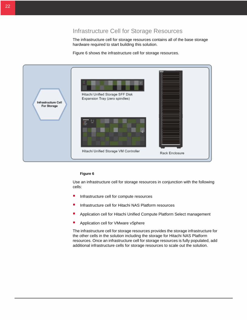
Infrastructure Cell for Storage ResourcesThe infrastructure cell for storage resources contains all of the base storage hardware required to start building this solution.
Figure 6 shows the infrastructure cell for storage resources.
Figure 6
Use an infrastructure cell for storage resources in conjunction with the following cells:
Infrastructure cell for compute resources
Infrastructure cell for Hitachi NAS Platform resources
Application cell for Hitachi Unified Compute Platform Select management
Application cell for VMware vSphere
The infrastructure cell for storage resources provides the storage infrastructure for the other cells in the solution including the storage for Hitachi NAS Platform resources. Once an infrastructure cell for storage resources is fully populated, add additional infrastructure cells for storage resources to scale out the solution.
23
23
Table 4 shows the components of the infrastructure cell for storage.
The infrastructure cell for storage resources contains a Hitachi Unified Storage VM controller and a disk expansion tray. This disk expansion tray holds disks for this infrastructure cell. Add storage disks to this cell for the following:
Application cell for Hitachi Unified Compute Platform Select management
Hot spares (optional)
Note — Scalability limits depend on application workloads running on this infrastructure.
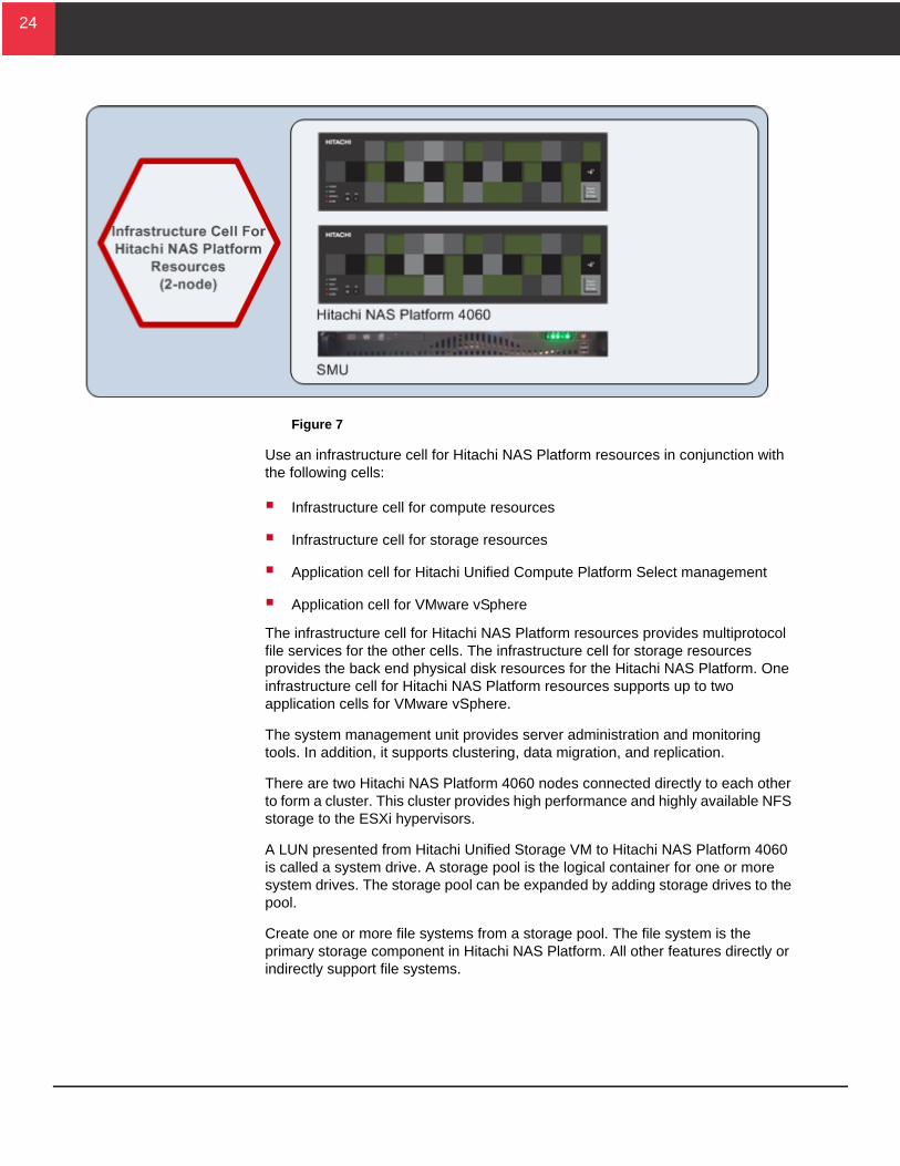
Infrastructure Cell for Hitachi NAS Platform ResourcesThe infrastructure cell for Hitachi NAS Platform resources contains the file module components for building out a network attached storage infrastructure with high availability.
Figure 7 on page 24 shows the infrastructure cell for Hitachi NAS Platform.
Table 4. Infrastructure Cell for Storage Resources Hardware
Hardware Description Version Quantity
Hitachi Unified Storage VM Dual Controllers and Fibre Channel Modules
16 × 8 GB/sec Fibre Channel Ports
32 GB total cache
73-02-03-00 or later 1
SFF disk expansion tray for Hitachi Unified Storage VM
Contains Disks for other Cells
1
24
24
Figure 7
Use an infrastructure cell for Hitachi NAS Platform resources in conjunction with the following cells:
Infrastructure cell for compute resources
Infrastructure cell for storage resources
Application cell for Hitachi Unified Compute Platform Select management
Application cell for VMware vSphere
The infrastructure cell for Hitachi NAS Platform resources provides multiprotocol file services for the other cells. The infrastructure cell for storage resources provides the back end physical disk resources for the Hitachi NAS Platform. One infrastructure cell for Hitachi NAS Platform resources supports up to two application cells for VMware vSphere.
The system management unit provides server administration and monitoring tools. In addition, it supports clustering, data migration, and replication.
There are two Hitachi NAS Platform 4060 nodes connected directly to each other to form a cluster. This cluster provides high performance and highly available NFS storage to the ESXi hypervisors.
A LUN presented from Hitachi Unified Storage VM to Hitachi NAS Platform 4060 is called a system drive. A storage pool is the logical container for one or more system drives. The storage pool can be expanded by adding storage drives to the pool.
Create one or more file systems from a storage pool. The file system is the primary storage component in Hitachi NAS Platform. All other features directly or indirectly support file systems.
25
25
For this solution, the VMware vSphere infrastructure uses NFS exports from a file system to connect to the storage resources provided by Hitachi NAS Platform 4060.
Table 5 shows the components of the infrastructure cell for Hitachi NAS Platform resources.
Network InfrastructureThe network design for network attached storage in this solution uses the following:
Link aggregation (LACP)
Combination of two 10 Gb/sec Ethernet ports (out of four) into a single logical link to provide increased bandwidth, load balancing, and higher link availability.
Two 10 Gb/sec Ethernet ports on each node connected to two Cisco Nexus 5548UP switches (1 connection each) using link aggregation
This provides high bandwidth and high availability in case of a switch failure.
Jumbo frames
Link aggregate interface MTU size to 9000 configured to support jumbo frames
VLANs
Separate NFS traffic from VMware vSphere management, VMware vMotion, and virtual machine network traffic
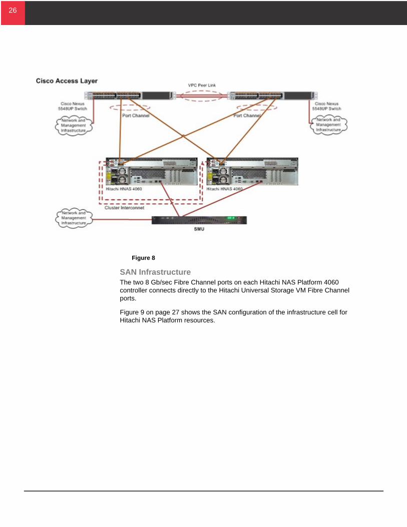
Figure 8 shows the physical network configuration of the infrastructure cell for Hitachi NAS Platform resources.
Table 5. Infrastructure Cell for Hitachi NAS Platform Resources
Hardware Description Version Quantity
Hitachi NAS Platform 4060 2 × 10 Gb/sec Cluster Ports
4 × 10 Gb/sec Ethernet Ports
4 × 8 Gb/sec Fibre Channel Ports
11.1 2
System Management Unit 2 × 1 Gb/sec Ethernet Ports 11.1 1
26
26
Figure 8
SAN InfrastructureThe two 8 Gb/sec Fibre Channel ports on each Hitachi NAS Platform 4060 controller connects directly to the Hitachi Universal Storage VM Fibre Channel ports.
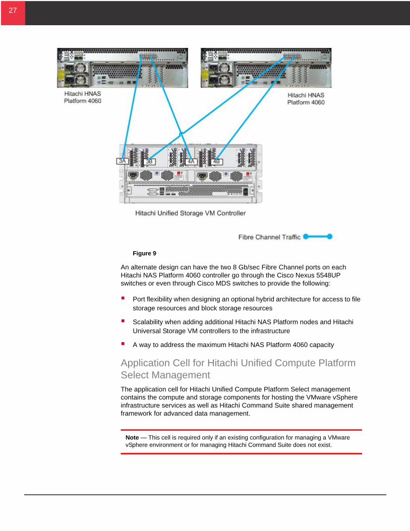
Figure 9 on page 27 shows the SAN configuration of the infrastructure cell for Hitachi NAS Platform resources.
27
27
Figure 9
An alternate design can have the two 8 Gb/sec Fibre Channel ports on each Hitachi NAS Platform 4060 controller go through the Cisco Nexus 5548UP switches or even through Cisco MDS switches to provide the following:
Port flexibility when designing an optional hybrid architecture for access to file storage resources and block storage resources
Scalability when adding additional Hitachi NAS Platform nodes and Hitachi Universal Storage VM controllers to the infrastructure
A way to address the maximum Hitachi NAS Platform 4060 capacity
Application Cell for Hitachi Unified Compute Platform Select ManagementThe application cell for Hitachi Unified Compute Platform Select management contains the compute and storage components for hosting the VMware vSphere infrastructure services as well as Hitachi Command Suite shared management framework for advanced data management.
Note — This cell is required only if an existing configuration for managing a VMware vSphere environment or for managing Hitachi Command Suite does not exist.
28
28
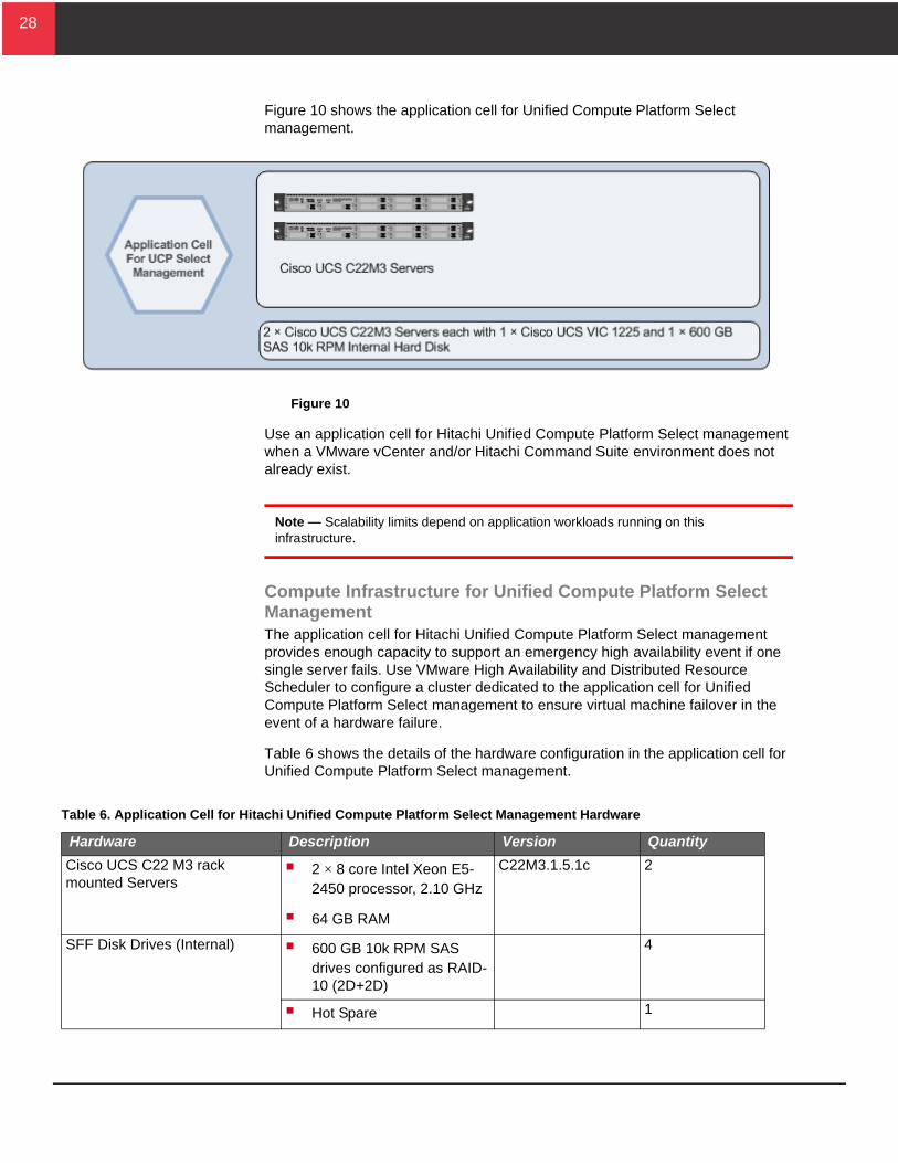
Figure 10 shows the application cell for Unified Compute Platform Select management.
Figure 10
Use an application cell for Hitachi Unified Compute Platform Select management when a VMware vCenter and/or Hitachi Command Suite environment does not already exist.
Note — Scalability limits depend on application workloads running on this infrastructure.
Compute Infrastructure for Unified Compute Platform Select ManagementThe application cell for Hitachi Unified Compute Platform Select management provides enough capacity to support an emergency high availability event if one single server fails. Use VMware High Availability and Distributed Resource Scheduler to configure a cluster dedicated to the application cell for Unified Compute Platform Select management to ensure virtual machine failover in the event of a hardware failure.
Table 6 shows the details of the hardware configuration in the application cell for Unified Compute Platform Select management.
Table 6. Application Cell for Hitachi Unified Compute Platform Select Management Hardware
Hardware Description Version Quantity
Cisco UCS C22 M3 rack mounted Servers
2 × 8 core Intel Xeon E5-2450 processor, 2.10 GHz
64 GB RAM
C22M3.1.5.1c 2
SFF Disk Drives (Internal) 600 GB 10k RPM SAS drives configured as RAID-10 (2D+2D)
4
Hot Spare 1
29
29
The compute infrastructure of the application cell for Unified Compute Platform Select management supports all associated Hitachi Command Suite, Microsoft® SQL Server®, Microsoft Active Directory®, VMware vCenter, and their associated requirements.
Manage your environment using the above resources or by connecting to a preexisting VMware vSphere and Hitachi Command Suite management environment.
Network Infrastructure for Unified Compute Platform Select ManagementConfigure each of the C22M3 servers with two NICs connected to the infrastructure network. All management and vMotion traffic flows through these NICs.
Optionally, these C22M3 servers can be connected to the Cisco UCS fabric using Cisco UCS 2232PP Fabric Extenders and configured for High Availability. This means these C22M3 servers are no longer standalone, but are deployed in an integrated model and managed by Cisco UCS Manager.
Storage Infrastructure for Unified Compute Platform Select ManagementThe storage infrastructure of the application cell for Hitachi Unified Compute Platform Select management consists of five units of 600 GB 10k RPM SAS drives internal to each of the Cisco UCS C22M3 server blades.
Configure the storage into a single RAID-10 (2D+2D) group. The RAID group provides an overall capacity of 1.2 TB.
Configure 1 unit of 600 GB 10k RPM SAS drives internal as a spare to protect against a single drive failure.
Optionally, the storage infrastructure may reside on one of the dynamic provisioning pools on Hitachi Unified Storage VM and may be set up for SAN boot.
30
30
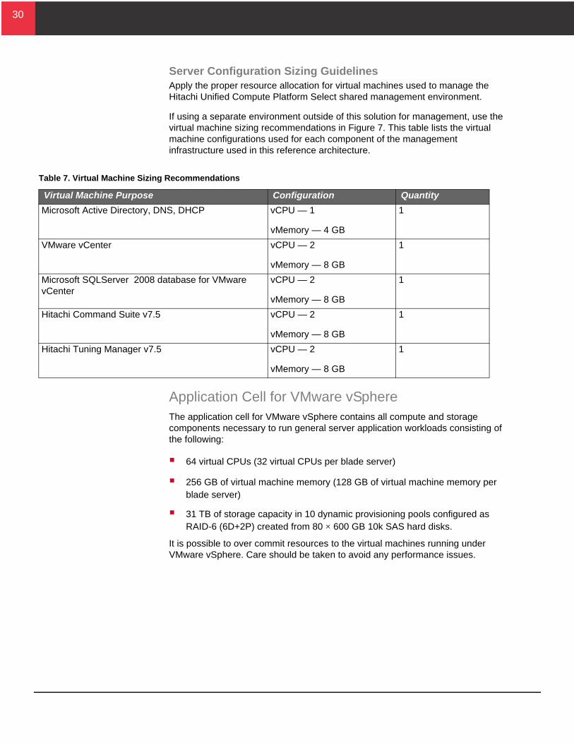
Server Configuration Sizing GuidelinesApply the proper resource allocation for virtual machines used to manage the Hitachi Unified Compute Platform Select shared management environment.
If using a separate environment outside of this solution for management, use the virtual machine sizing recommendations in Figure 7. This table lists the virtual machine configurations used for each component of the management infrastructure used in this reference architecture.
Application Cell for VMware vSphereThe application cell for VMware vSphere contains all compute and storage components necessary to run general server application workloads consisting of the following:
64 virtual CPUs (32 virtual CPUs per blade server)
256 GB of virtual machine memory (128 GB of virtual machine memory per blade server)
31 TB of storage capacity in 10 dynamic provisioning pools configured as RAID-6 (6D+2P) created from 80 × 600 GB 10k SAS hard disks.
It is possible to over commit resources to the virtual machines running under VMware vSphere. Care should be taken to avoid any performance issues.
Table 7. Virtual Machine Sizing Recommendations
Virtual Machine Purpose Configuration Quantity
Microsoft Active Directory, DNS, DHCP vCPU — 1
vMemory — 4 GB
1
VMware vCenter vCPU — 2
vMemory — 8 GB
1
Microsoft SQLServer 2008 database for VMware vCenter
vCPU — 2
vMemory — 8 GB
1
Hitachi Command Suite v7.5 vCPU — 2
vMemory — 8 GB
1
Hitachi Tuning Manager v7.5 vCPU — 2
vMemory — 8 GB
1
31
31
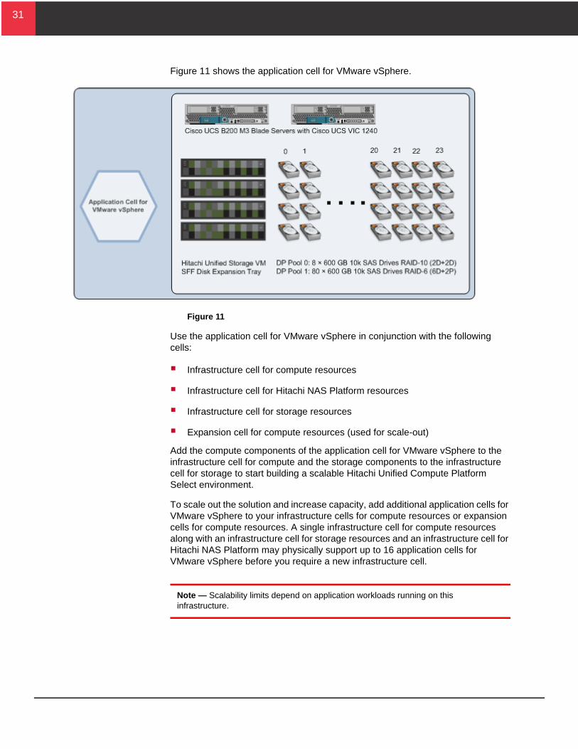
Figure 11 shows the application cell for VMware vSphere.
Figure 11
Use the application cell for VMware vSphere in conjunction with the following cells:
Infrastructure cell for compute resources
Infrastructure cell for Hitachi NAS Platform resources
Infrastructure cell for storage resources
Expansion cell for compute resources (used for scale-out)
Add the compute components of the application cell for VMware vSphere to the infrastructure cell for compute and the storage components to the infrastructure cell for storage to start building a scalable Hitachi Unified Compute Platform Select environment.
To scale out the solution and increase capacity, add additional application cells for VMware vSphere to your infrastructure cells for compute resources or expansion cells for compute resources. A single infrastructure cell for compute resources along with an infrastructure cell for storage resources and an infrastructure cell for Hitachi NAS Platform may physically support up to 16 application cells for VMware vSphere before you require a new infrastructure cell.
Note — Scalability limits depend on application workloads running on this infrastructure.
32
32
Compute InfrastructureThe application cell for VMware vSphere supports a maximum density of 64 virtual CPUs and 256 GB of virtual machine memory. It is possible to over commit resources and increase these limits of maximum density but in such a maximum density configuration, a cell cannot support the failover of virtual machines in case of a server blade failure. To provide high availability, do the following:
Reduce the number of virtual CPUs and virtual machine memory per host up to 50%
Configure a VMware High Availability and Distributed Resource Scheduler cluster dedicated to application cells for VMware vSphere
Place additional hosts from each application cell for VMware vSphere into the cluster. When scaling the solution, increase the number of virtual machines per host as you add more resources to the cluster.
Based on VMware maximums, each High Availability and Distributed Resource Scheduler cluster can support up to 16 application cells for VMware vSphere (32 hosts).
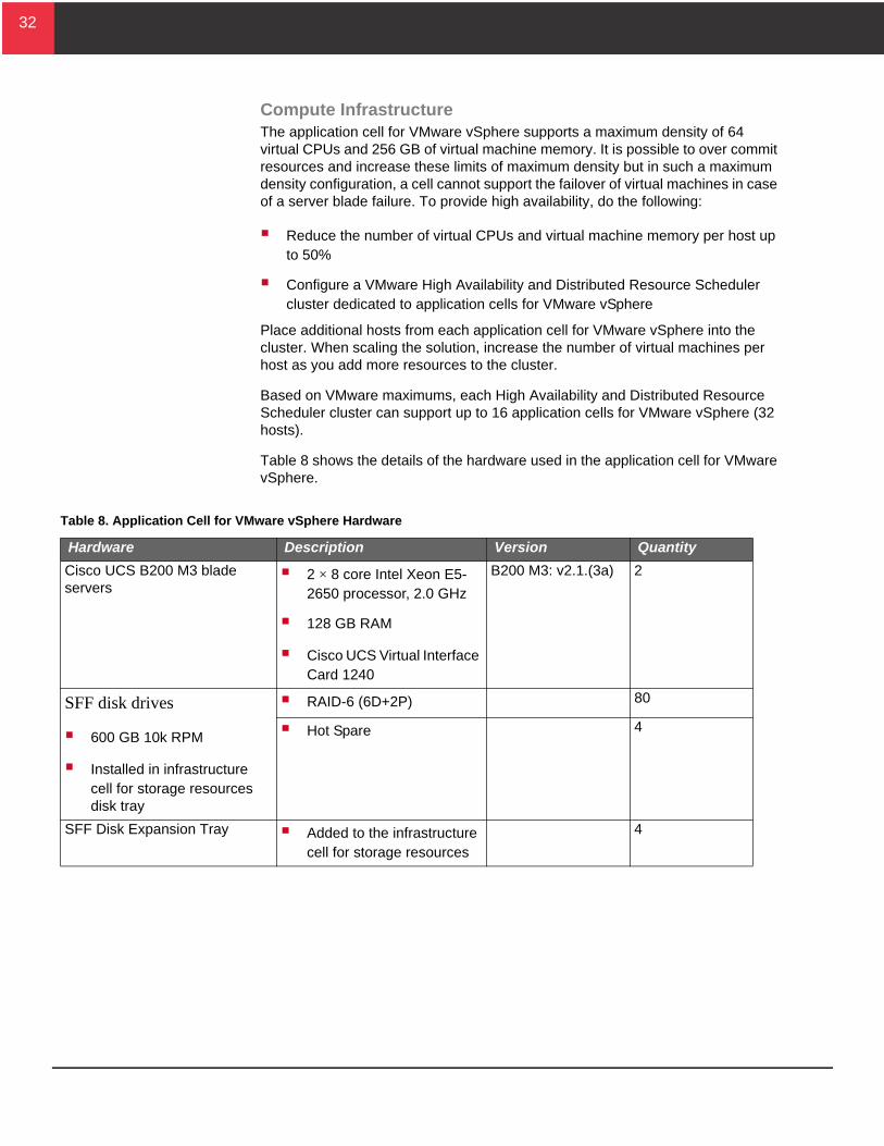
Table 8 shows the details of the hardware used in the application cell for VMware vSphere.
Table 8. Application Cell for VMware vSphere Hardware
Hardware Description Version Quantity
Cisco UCS B200 M3 blade servers
2 × 8 core Intel Xeon E5-2650 processor, 2.0 GHz
128 GB RAM
Cisco UCS Virtual Interface Card 1240
B200 M3: v2.1.(3a) 2
SFF disk drives
600 GB 10k RPM
Installed in infrastructure cell for storage resources disk tray
RAID-6 (6D+2P) 80
Hot Spare 4
SFF Disk Expansion Tray Added to the infrastructure cell for storage resources
4
33
33
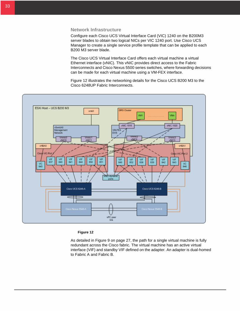
Network InfrastructureConfigure each Cisco UCS Virtual Interface Card (VIC) 1240 on the B200M3 server blades to obtain two logical NICs per VIC 1240 port. Use Cisco UCS Manager to create a single service profile template that can be applied to each B200 M3 server blade.
The Cisco UCS Virtual Interface Card offers each virtual machine a virtual Ethernet interface (vNIC). This vNIC provides direct access to the Fabric Interconnects and Cisco Nexus 5500 series switches, where forwarding decisions can be made for each virtual machine using a VM-FEX interface.
Figure 12 illustrates the networking details for the Cisco UCS B200 M3 to the Cisco 6248UP Fabric Interconnects.
Figure 12
As detailed in Figure 9 on page 27, the path for a single virtual machine is fully redundant across the Cisco fabric. The virtual machine has an active virtual interface (VIF) and standby VIF defined on the adapter. An adapter is dual-homed to Fabric A and Fabric B.
34
34
Combined with Cisco UCS Fabric Failover, the VM-FEX solution provides fault tolerance and removes the need for software based high availability teaming mechanisms. If the active uplink fails, the vNIC automatically fails over to the standby uplink and simultaneously update the network through gratuitous ARP. In Figure 12 on page 33, the active links are solid and the standby links are dashed.
Following best practice, separate following traffic to achieve greater security and better performance:
ESXi-Mgmt — Chassis management connections and primary management of the ESXi hypervisors
vMotion — Configured for VMware vMotion
VM-Data — Configured for the virtual machine network
storage-NFS — Configured for NFS traffic
Hitachi NAS Platform InfrastructureThe Hitachi NAS Platform infrastructure of the application cell for VMware vSphere consists of twelve 1 TB system disks presented as LDEVs carved out of the dynamic provisioning pool on Hitachi Unified Storage VM to each Hitachi NAS Platform 4060 node. See “Storage Infrastructure” on page 35 for more information on how to configure the dynamic provisioning pool.
In case you expect high random read and write rates of the server application workloads, build the dynamic provisioning pool using RAID-10.
Each Hitachi NAS Platform 4060 node contains four storage pools, four file systems, and two enterprise virtual servers (EVS). The EVS hosts these file systems. When requiring additional capacity, add additional system drives to the storage pool and file systems can grow on the fly. Each node can concurrently access system drives. Therefore, present all system drives to all nodes in a Hitachi NAS Platform cluster, so any node can access the stored data during a failover event.
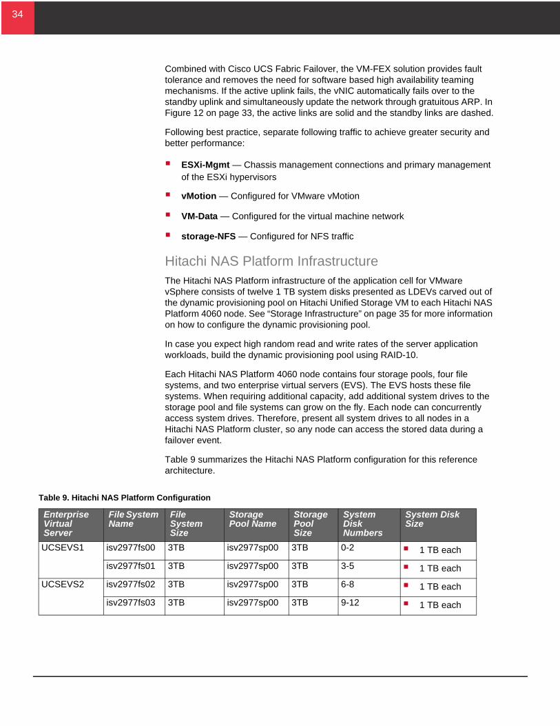
Table 9 summarizes the Hitachi NAS Platform configuration for this reference architecture.
Table 9. Hitachi NAS Platform Configuration
Enterprise Virtual Server
File System Name
File System Size
Storage Pool Name
Storage Pool Size
System Disk Numbers
System Disk Size
UCSEVS1 isv2977fs00 3TB isv2977sp00 3TB 0-2 1 TB each
isv2977fs01 3TB isv2977sp00 3TB 3-5 1 TB each
UCSEVS2 isv2977fs02 3TB isv2977sp00 3TB 6-8 1 TB each
isv2977fs03 3TB isv2977sp00 3TB 9-12 1 TB each
35
35
Configure Hitachi NAS Platform 4060 following the following best practice recommendations:
Disable the read ahead cache on the Hitachi NAS Platform 4060 cluster.
Use a 4 KB file system block size with VMware environments.
Install and use the VMware VAAI for NAS adapter for Hitachi NAS Platform.
Optionally use Hitachi NAS Virtual Infrastructure Integrator to manage snapshots and file clones from within VMware vCenter.
NAS Platform 4060 enables primary deduplication by default, starting with version 11.2 software.
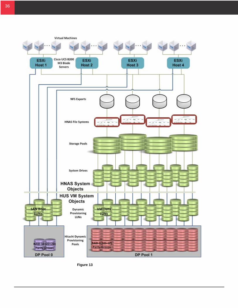
Storage InfrastructureThe storage infrastructure of the application cell for VMware vSphere consists of 80 units of 600 GB 10k RPM SAS drives in one dynamic provisioning pool with the following configuration:
Number of SFF Trays — 4
Number of Hard Disk Drives — 96 (24 per tray)
Dynamic Provisioning Pool 0 — 8 drives consisting of 2 parity groups configured as RAID-10 (2D+2D)
Dynamic Provisioning Pool 1 — 80 drives consisting of 10 parity groups configured as RAID-6 (6D+2P)
Figure 13 on page 36 shows the storage configuration for the application cell for VMware vSphere.
36
36
Figure 13
37
37
As a best practice, do the following:
Use RAID-10 to maximize performance for random workloads, which is common with virtualized environments.
Use RAID-6 to balance performance and efficient use of pool space. Hitachi Data Systems recommends RAID-6 when you need a guarantee against data loss when other associated recommendations are also followed.
Create two pools to separate virtual machine workloads with different performance characteristics.
Because of its wide striping capability, use Hitachi Dynamic Provisioning to balance the I/O load in pools of RAID groups. Mixing workloads in a single dynamic provisioning pool is possible to obtain certain levels of performance. However, grouping virtual machines with similar I/O profiles optimizes storage performance and results in a more efficient use of disk resources. Within a pool, create additional LUNs as necessary to spread the workload and avoid possible queue depth issues.
When scaling out with additional application cells for VMware vSphere, add parity groups to grow the existing pools. Increasing spindle count allows the pool to support the increasing IOPS requirement dynamically. Create additional LUNs to assign to VMDKs (virtual machine disk) to prevent virtual machine workloads from saturating the LUN. Dynamic provisioning pools may grow to 60 TB.
SAN InfrastructureUse Cisco UCS Manager to create a single service profile template that can be applied to each of B200 M3 server blade.
Configure each Cisco UCS Virtual Interface Card (VIC) 1240 on the B200M3 server blades to obtain one logical HBA per VIC 1240 port.
The Cisco UCS VIC offers each virtual machine a virtual HBA interface (vHBA). This vHBA provides direct access to the Fabric Interconnects and Cisco Nexus 5500 series switches where forwarding decisions can be made for each virtual machine using a VM-FEX interface.
See Figure 12 on page 33 to see the Fibre Channel traffic paths.
The environment uses single initiator to multi-target zoning for each port on the Cisco B200 M3 server blades. Following best practice, configure the SAN environment in a dual fabric topology for redundancy and high availability. This results in four paths available to each ESXi host, providing the following:
Resiliency to failure
Redundant paths to the storage subsystem
The storage multi-path policy for each target in ESXi was set to round robin. This results in optimal load distribution during an all paths available situation.
38
38
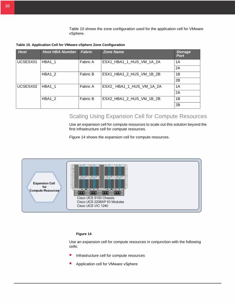
Table 10 shows the zone configuration used for the application cell for VMware vSphere.
Scaling Using Expansion Cell for Compute ResourcesUse an expansion cell for compute resources to scale out this solution beyond the first infrastructure cell for compute resources.
Figure 14 shows the expansion cell for compute resources.
Figure 14
Use an expansion cell for compute resources in conjunction with the following cells:
Infrastructure cell for compute resources
Application cell for VMware vSphere
Table 10. Application Cell for VMware vSphere Zone Configuration
Host Host HBA Number Fabric Zone Name Storage Port
UCSESX01 HBA1_1 Fabric A ESX1_HBA1_1_HUS_VM_1A_2A 1A
2A
HBA1_2 Fabric B ESX1_HBA1_2_HUS_VM_1B_2B 1B
2B
UCSESX02 HBA1_1 Fabric A ESX2_ HBA1_1_HUS_VM_1A_2A 1A
2A
HBA1_2 Fabric B ESX2_HBA1_2_HUS_VM_1B_2B 1B
2B
39
39
Once the chassis in the infrastructure cell for compute resources becomes fully populated, use an expansion cell for compute resources to provide additional resource capacity. This expansion cell for compute resources uses the storage and networking infrastructure provided in the following:
Infrastructure cell for compute resources
Infrastructure cell for storage resources
Hitachi NAS Platform resources
House this cell in the rack enclosure of the infrastructure cell for compute resources.
You can physically add up to three expansion cells for compute resources for each infrastructure cell for compute resources, infrastructure cell for storage resources, and infrastructure cell for Hitachi NAS Platform resources. If you need more expansion cells, add new infrastructure to your environment.
One infrastructure cell for compute resources and two expansion cells for compute resources may support a maximum of 12 application cells for VMware vSphere (24 server blades and 33 storage trays).
Note — Scalability limits depend on application workloads running on this infrastructure.
Chassis ComponentsThe expansion cell for compute resources uses the same chassis components contained in the infrastructure cell for compute resources.
Networking InfrastructureThe networking for the expansion cell for compute resources uses the same networking configurations as the infrastructure cell for compute resources.
Hitachi NAS Platform InfrastructureThe Hitachi NAS Platform infrastructure for the expansion cell for compute resources uses the same configurations as the infrastructure cell for Hitachi NAS Platform resources. Use the two additional 10 gigabit Ethernet ports on each of Hitachi NAS Platform 4060 to provide more bandwidth. Create and consume additional file services objects to provide scalable storage for the solution.
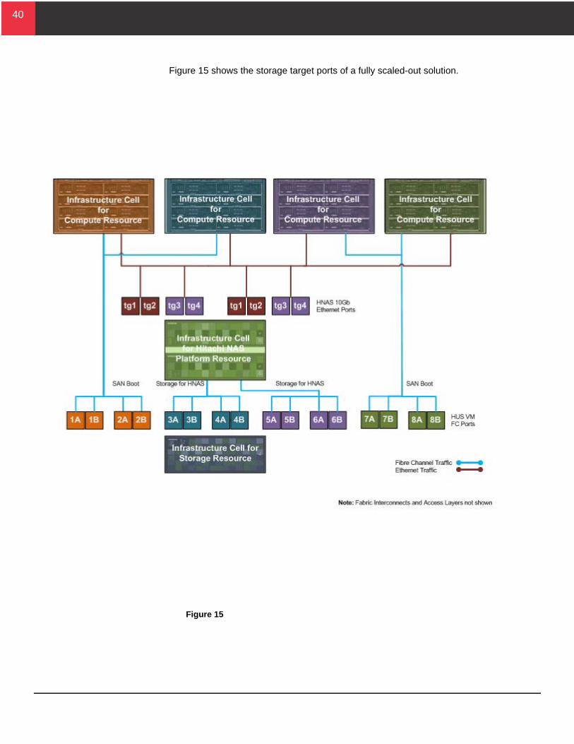
Storage InfrastructureUse four of the open storage target ports on Hitachi Unified Storage VM in the infrastructure cell for storage resources. Follow the same storage configuration described for the infrastructure cell for compute resources to use the newly provisioned storage target ports in the zoning configuration.
40
40
Figure 15 shows the storage target ports of a fully scaled-out solution.
Figure 15
41
41
Scaling Using Expansion Cell for Storage ResourcesUse an expansion cell for storage resources to scale out the VMware vSphere solution beyond the first infrastructure cell for storage resources.
The expansion cell for storage contains up to 4 units of 2.5 inch SFF disk trays for Hitachi Unified Storage VM.
Use an expansion cell for storage resources in conjunction with the following cells:
Infrastructure cell for storage resources
Infrastructure cell for Hitachi NAS Platform resource
Application cell for VMware vSphere
After filling the original infrastructure cell for storage drive chassis, use an expansion cell for storage resources to provide additional capacity.
Put hot spares for the first application cells in the disk tray for the infrastructure cell for storage resources. When the tray in the infrastructure cell fills, use the expansion cell for storage resources.
42
42
Engineering ValidationThis describes the test methodology, test load and the verification tests used to validate this reference architecture. The reference architecture consists of systems and solutions that are designed, tested and documented to facilitate and improve your deployment.
Test MethodologyThe focus of the testing methodology was on validating the benefits of Hitachi Unified Compute Platform Select for VMware vSphere with Cisco Unified Computing System using Hitachi Unified Storage VM and Hitachi NAS Platform. This includes the following:
The differentiated features that provide better utilization of compute resources by moving functions previously handled by the server onto the storage platform
The ability to better control how storage traffic flows through the system
The systems validation tests, including differentiated feature benefit analysis, included:
High availability-resiliency
High availability of Hitachi NAS Platform
High availability of Hitachi Unified Storage VM
Dynamic provisioning with Hitachi Storage Virtual Operating System
VMware API for Array Integration
Advanced Cisco UCS SAN features:
Link aggregation (F-port trunk)
F-port port channel
Test InfrastructureTesting involved these cells:
Infrastructure cell for compute resources
Infrastructure cell for Hitachi NAS Platform resources
Infrastructure cell for storage resources
Application cell for Unified Compute Platform Select management
43
43
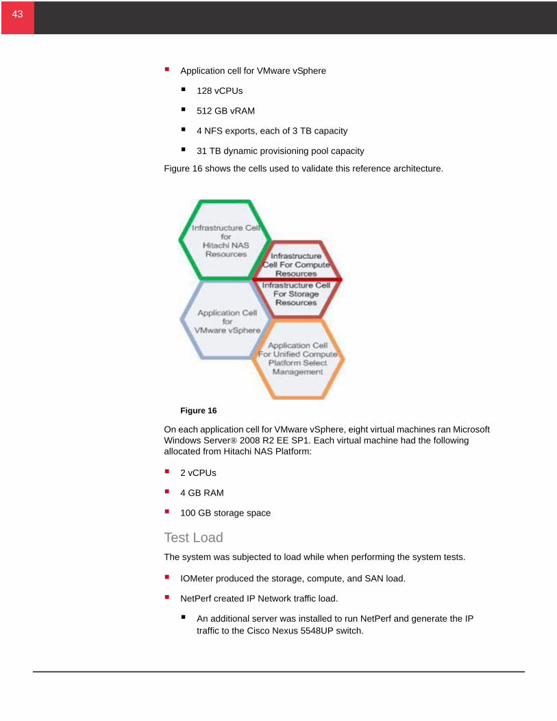
Application cell for VMware vSphere
128 vCPUs
512 GB vRAM
4 NFS exports, each of 3 TB capacity
31 TB dynamic provisioning pool capacity
Figure 16 shows the cells used to validate this reference architecture.
Figure 16
On each application cell for VMware vSphere, eight virtual machines ran Microsoft Windows Server® 2008 R2 EE SP1. Each virtual machine had the following allocated from Hitachi NAS Platform:
2 vCPUs
4 GB RAM
100 GB storage space
Test LoadThe system was subjected to load while when performing the system tests.
IOMeter produced the storage, compute, and SAN load.
NetPerf created IP Network traffic load.
An additional server was installed to run NetPerf and generate the IP traffic to the Cisco Nexus 5548UP switch.
44
44
Interoperability VerificationBefore and during the build of the environment, it was ensured that the HiFIRE Interoperability Test database supported all the deployed hardware components, firmware, and software. All make, model and version numbers were documented.
High Availability/Resiliency VerificationSystem resiliency verification (high availability) testing was limited to major component failures in order to demonstrate system resiliency at each layer of the solution. The cases tested and validated the following:
I/O Module failure and recovery
Fabric Interconnect failure and recovery
Fabric Interconnect SAN uplink (F-port port channel) failure and recovery
Cisco Nexus 5000 failure and recovery
Hitachi Unified Storage VM controller failure (FED failure on one cluster) and recovery
Demonstrate VMware vMotion by migrating a virtual machine server between two ESX hosts
Demonstrate high availability failover for Cisco UCS blade server with VMware High Availability
Hitachi NAS Platform node failure and recovery
Hitachi NAS Platform 8 Gb/sec Fibre channel port failure and recovery
Hitachi NAS Platform 10 Gb/sec Ethernet port failure and recovery
45
45
VMware vStorage APIs for Array Integration (VAAI) VerificationThe following is the verification made for VMware vStorage APIs for Array Integration (VAAI) during validation:
VAAI Full Copy — Clone virtual machines: eagerzeroedthick to eagerzeroedthick vmdk
VAAI Full Copy —- Clone virtual machines: eagerzeroedthick to zeroedthick vmdk
VAAI Full Copy —- Clone virtual machines: eagerzeroedthick to thin vmdk
VAAI Full Copy — Clone virtual machines: zeroedthick to zeroedthick vmdk
VAAI Full Copy — Clone virtual machines: zeroedthick to thin vmdk
VAAI Full Copy — Clone virtual machines: (thin to zeroedthick vmdk
VAAI Full Copy — Clone virtual machines: thin to thin vmdk
VAAI Full Copy —Storage vMotion virtual machines: zeroedthick to zeroedthick vmdk
VAAI Block Zeroing — Provisioning eagerzeroedthick vmdk
VAAI Hardware Assisted Locking — Large scale virtual machine boot storms
VAAI Hardware Assisted Locking — Large scale simultaneous vMotion
VAAI + Dynamic Provisioning Hardware-Accelerated Thin Provisioning — eagerzeroedthick vmdks
46
46
ConclusionThis reference architecture guide discusses how to design the Hitachi Unified Compute Platform Select for VMware vSphere with Cisco Unified Computing System using Hitachi Unified Storage VM and Hitachi NAS Platform reference architecture. The purpose of the general server application workloads testing in the Hitachi Data Systems ISV Solutions and Engineering laboratory was to provide general guidance on the virtual resources available with this solution.
Each implementation has its own unique set of data center and application requirements. Design your implementation of this environment by understanding the I/O workload of the server applications in your environment. Creating an environment that meets your unique needs results in increased ROI from avoiding over or under provisioning resources.
Use Hitachi Dynamic Provisioning to reallocate I/O capabilities dynamically, as necessary. Having the capability to provision additional spindles to an already provisioned datastore within VMware vSphere allows for nondisruptive upgrades to the underlying storage infrastructure. This provides immediate benefits to your environment without confusing shuffling of virtual machines, datastores, or LUs.
This Unified Compute Platform Select design gives you a build-as-you-go model that uses performance-proven hardware resources, including Hitachi Unified Storage VM and Cisco UCS. The modular design, using a cell architecture, permits initially implementing an environment for modest needs that gives you the flexibility to scale out as your IT needs grow.
For More InformationHitachi Data Systems Global Services offers experienced storage consultants, proven methodologies and a comprehensive services portfolio to assist you in implementing Hitachi products and solutions in your environment. For more information, see the Hitachi Data Systems Global Services website.
Live and recorded product demonstrations are available for many Hitachi products. To schedule a live demonstration, contact a sales representative. To view a recorded demonstration, see the Hitachi Data Systems Corporate Resources website. Click the Product Demos tab for a list of available recorded demonstrations.
Hitachi Data Systems Academy provides best-in-class training on Hitachi products, technology, solutions and certifications. Hitachi Data Systems Academy delivers on-demand web-based training (WBT), classroom-based instructor-led training (ILT) and virtual instructor-led training (vILT) courses. For more information, see the Hitachi Data Systems Services Education website.
For more information about Hitachi products and services, contact your sales representative or channel partner or visit the Hitachi Data Systems website.
Corporate Headquarters2845 Lafayette Street, Santa Clara, California 95050-2627 USAwww.HDS.com
Regional Contact InformationAmericas: +1 408 970 1000 or [email protected], Middle East and Africa: +44 (0) 1753 618000 or [email protected] Asia-Pacific: +852 3189 7900 or [email protected]
© Hitachi Data Systems Corporation 2014. All rights reserved. HITACHI is a trademark or registered trademark of Hitachi, Ltd. Innovate With Information is a trademark or registered trademark of Hitachi Data Systems Corporation. Microsoft, Windows Server, SQL Server, and Active Directory are trademarks or registered trademarks of Microsoft Corporation. All other trademarks, service marks, and company names are properties of their respective owners.
Notice: This document is for informational purposes only, and does not set forth any warranty, expressed or implied, concerning any equipment or service offered or to be offered by Hitachi Data Systems Corporation.
AS-264-02, May2014