deposition supplementary informationchemicalfor … · figure s3. ferroelectric resistive switching...
TRANSCRIPT

Supplementary Information for
Large resistive switching and switchable photovoltaic response in
ferroelectric doped BiFeO3-based thin films by chemical solution
deposition
Linxing Zhang,1 Jun Chen,1,3,* Jiangli Cao,2 Dongyu He1 and Xianran Xing1,3,*
1Department of Physical Chemistry, University of Science and Technology Beijing, Beijing 100083, China
2Institute of Advanced Materials and Technology, University of Science and Technology Beijing, Beijing 100083, China
3State Key Laboratory for Advanced Metallurgy, University of Science and Technology Beijing, Beijing 100083, China
*Corresponding author. Tel.: +86 10 82375027; Electronic mail: [email protected], [email protected]
Electronic Supplementary Material (ESI) for Journal of Materials Chemistry C.This journal is © The Royal Society of Chemistry 2015

Topography image
Figure S1. Topography image of the BSFN films.
Ferroelectric resistive switching
Figure S2. Ferroelectric resistive switching for BSFN and BSF thin films with a
thickness of 250 nm. The inset shows the curves with semilogarithmic scale.

Figure S3. Ferroelectric resistive switching for BSFN thin films with a thickness of 120 nm. a) Direct current I-V characteristics dependent on voltage at room temperature. The inset shows the curves with semilogarithmic scale. b) The resistive ON/OFF as a function of reading voltages, which exhibits a largest value of 194 at a reading voltage of 1.3 V with a small writing voltage of 4 V.
Table S1 Comparison between different ferroelectric memristor.
Mechanism Heterostructure Ratio Ref.
switchable diode Pt/BFO/SRO/STO ~753 Adv. Mater., 2013, 25, 2339.
switchable diode Pt/BFO/Nb-STO ~5000 Appl. Phys. Lett., 2013, 102, 102901.
switchable diode Pt/BSFN/FTO ~12000 Current study
tunnel junction Pt/BTO/LSMO/NGO ~750 Nature, 2009, 460, 81.
tunnel junction Pt/BTO/Nb-STO ~12800 Nat. Mater., 2013, 12, 617.

Absorption spectrum
Figure S4. a) UV-visible absorption spectrum of the BSFN films on FTO glass substrate and the bare substrate. The inset shows the photograph. b) Plot of (F(R∞)E)2 vs. E. The linear extrapolation gives a band gap of 2.27 eV.
Ultraviolet photoelectron spectroscopy (UPS)
Figure S5. UPS cutoff spectra. a) The work function (φ) of BSFN and FTO. The difference between the two is less than 0.1 eV. The φ depends on the photon energy of UV and the bias voltage (in our case the photon energy of synchrotron radiation is 36.07 eV and the bias voltage is 5 eV). So the φ of BSFN is 36.07 - 26.86 - 5 = 4.21 eV. b) The valence band region of BSFN. |EVB-EF| is 1.58 eV. From Figure S4, we have obtained that the band gap of BSFN is 2.27 eV. Thus |EF-ECB| = 2.27 - 1.58 = 0.69 ev, which indicates that the present films are n-type semiconductors due to the few existing oxygen vacancies caused by the small Ni substitution. Furthermore, the electron affinity (χ) of films is estimated to be 4.21 - 0.69 = 3.52 eV, consistent with that reported.1
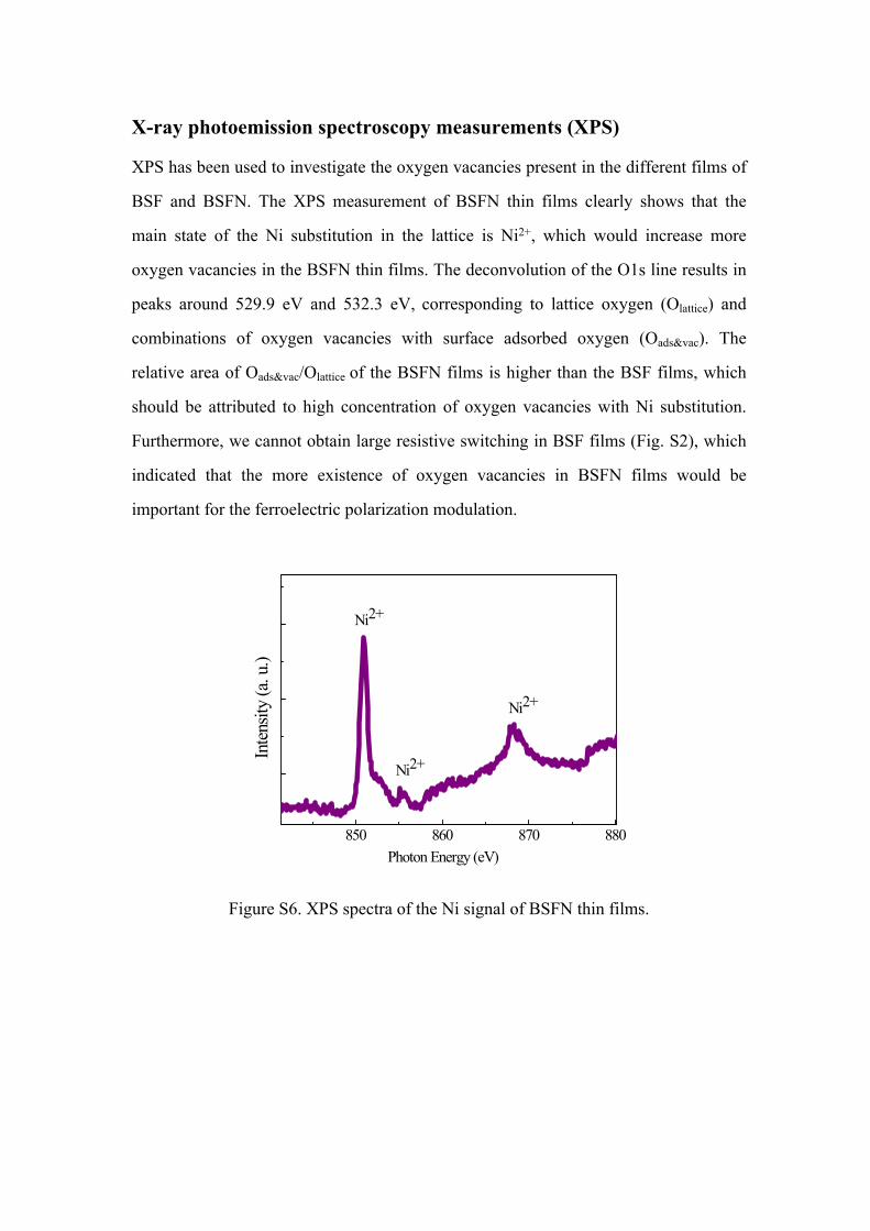
X-ray photoemission spectroscopy measurements (XPS)
XPS has been used to investigate the oxygen vacancies present in the different films of
BSF and BSFN. The XPS measurement of BSFN thin films clearly shows that the
main state of the Ni substitution in the lattice is Ni2+, which would increase more
oxygen vacancies in the BSFN thin films. The deconvolution of the O1s line results in
peaks around 529.9 eV and 532.3 eV, corresponding to lattice oxygen (Olattice) and
combinations of oxygen vacancies with surface adsorbed oxygen (Oads&vac). The
relative area of Oads&vac/Olattice of the BSFN films is higher than the BSF films, which
should be attributed to high concentration of oxygen vacancies with Ni substitution.
Furthermore, we cannot obtain large resistive switching in BSF films (Fig. S2), which
indicated that the more existence of oxygen vacancies in BSFN films would be
important for the ferroelectric polarization modulation.
850 860 870 880
Ni2+
Ni2+Inten
sity
(a. u
.)
Photon Energy (eV)
Ni2+
Figure S6. XPS spectra of the Ni signal of BSFN thin films.

Figure S7. XPS spectra of the O1s signal of BSF and BSFN thin films, respectively.
I-V conduction measurements
Figure S8 The I-V conduction curves of up-polarization and down-polarization states for BSFN thin films.

Conduction mechanism
In order to investigation the conduction mechanism of the DC I-V curve at 9 V,
we divided the sweeping bias voltage into four parts, 0→9 V, 9→0 V, 0→-9 V, -9→0
V, respectively. Figure S9 a1)-a3) show three possible conduction mechanisms at the
sweeping bias voltage from 0 to 9 V. Log-log plot shows that the conduction is Ohmic
at low field from 0 to 1.5 V due to the slope of 0.93 closing to 1.00 (Figure S9 a1). The
slope at higher field is larger than 1 indicating other two mechanisms. Hence, we
plotted the semilogarithmic scale curves with log(J) and E, as seen in Figure S9 a2. The
curve fit with the straight lines from 1.5 to 4.5 V, suggesting that the Schottky barrier
model with thermionic emission process is predominant,2 which is correspond to the
log-log plot at the same voltage range with a large slope of 9.26. At high field from 4.5
to 9 V, Fowler-Norhdeim (FN) plot shows FN tunneling domination (Figure S9 a3). As
shown in Figure S9 b, the conduction mechanism is space-charge limited current
(SCLC) for the sweeping bias voltage from 9 to 0 V, according that the relation
between J and E satisfies the expression of J∝E2.3 Meanwhile, the conduction
mechanisms at the sweeping bias voltage from 0 to -9 V are SCLC, Ohmic, Schottky,
and FN from 0 to -2.4 V, -2.4 to -3.6 V, -3.6 to -5.1 V, and -5.1 to -9 V, respectively.
Also the conduction behavior follows Lampert’s theory of SCLC from -9 to 0 V.
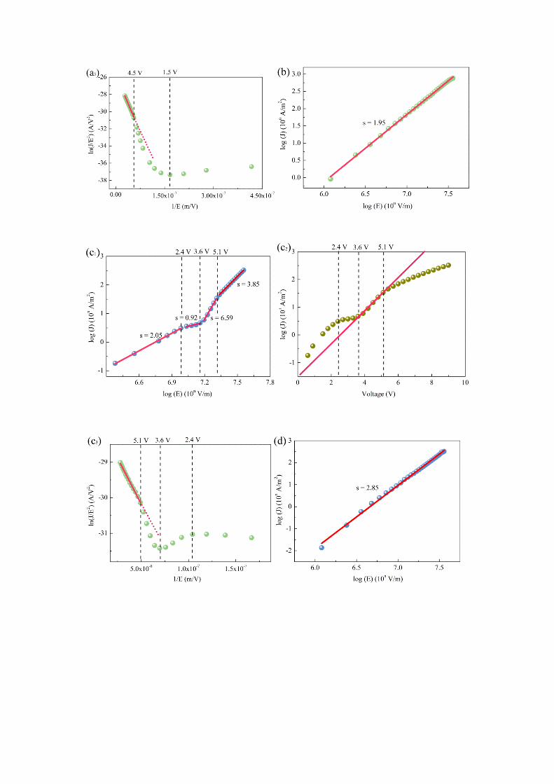

Figure S9. Conduction mechanism of the DC I-V curve at 9 V. a1)-a3) for 0→9 V, b) for 9→0 V, c1)-c3) for 0→-9 V, d) for -9→0 V, respectively. e) The summary of conduction mechanism.
References:1 S. J. Clark and J. Robertson, Appl. Phys. Lett., 2007, 90, 132903.2 S. M. Sze and K. K. Ng, in Physics of Semiconductor Devices, 3rd ed., John Wiley &
Sons, Inc., New Jersey, U. S. 2007, Ch. 3.3 M. A. Lampert, Phys. Rev., 1956, 103, 1648.