dept. of ee, ndhu 1 chapter 15 fading channels. dept. of ee, ndhu 2 digital communication systems
TRANSCRIPT
1Dept. of EE, NDHU
Chapter 15
Fading Channels

2Dept. of EE, NDHU
Digital Communication Systems

3Dept. of EE, NDHU
Challenges of Communicating Over Fading Channels
• Sources of noise degrade the system performance
– AWGN (ex. Thermal noise)
– Man-made and natural noise
– Interferences
• Band-limiting filter induces the ISI effect
• Radio channel results in propagation loss
– Signal attenuation versus distance over free space. For example,
– Multi-path fading cause fluctuations in the received amplitude, phase, angle of
arrival
2)4
()(d
dLs

4Dept. of EE, NDHU
Characterizing Mobile-radio Propagation
• Large-scale fading
– Signal power attenuation due to motion over large area
– Is caused by the prominent terrain (ex. hills, forest, billboard…)
between the transmitter and the receiver
– Statistics of path loss over the large-scale fading
+ Mean-path loss (nth-power law)
+ Log-normal distributed variation about the mean
– Is evaluated by averaging the received signal over 10 to 30
wavelengths
5Dept. of EE, NDHU
Characterizing Mobile-radio Propagation
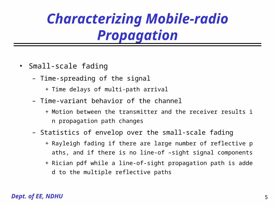
• Small-scale fading
– Time-spreading of the signal
+ Time delays of multi-path arrival
– Time-variant behavior of the channel
+ Motion between the transmitter and the receiver results in propagation path chang
es
– Statistics of envelop over the small-scale fading
+ Rayleigh fading if there are large number of reflective paths, and if there is no lin
e-of –sight signal components
+ Rician pdf while a line-of-sight propagation path is added to the multiple reflectiv
e paths

6Dept. of EE, NDHU
Basic Mechanisms for Signal Propagation
• Reflection
– Electromagnetic wave impinges on a smooth surface with very large
dimensions relative to the RF wavelength
• Diffraction
– Propagation path between the transmitter and the receiver is obstructed by a
dense body, causing secondary waves to be formed behind the obstructing
body
• Scattering
– A radio wave impinges on either a large, rough surface or any surface whose
dimensions are on the order of or less, causing the energy to be spread out

7Dept. of EE, NDHU
Fading Channel Manifestation
8Dept. of EE, NDHU
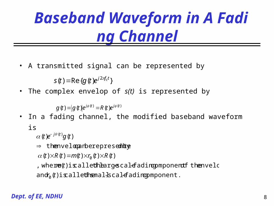
Baseband Waveform in A Fading Channel
• A transmitted signal can be represented by
• The complex envelop of s(t) is represented by
• In a fading channel, the modified baseband waveform is
component. fading-scale-small thecalled is )( and
envelop, theofcomponent fading-scale-large thecalled is )( where,
)()()()()(
by drepresente becan envelop the
)()(
0
0
)(
tr
tm
tRtrtmtRt
tget tj
})(Re{)( 2 tfj cetgts
)()( )()()( tjtj etRetgtg

9Dept. of EE, NDHU
Link-budget Considerations for A Fading Channel

10Dept. of EE, NDHU
Large-scale and Small-scale Fading

11Dept. of EE, NDHU
Large-scale Fading
• Channel model
– Okumura made some of the path-loss measurements for a wide range of ante
nna heights and coverage distance
– Hata transformed Okumura’s data into parametric formulas
• The mean path-loss is a function of distance between a transmitter a
nd receiver
– n-th power of d
– n is equal to 2 in free space, n can be lower while a very strong guided wave
is present, and n can be larger while obstructions are present
)(dLp
)log(10)( )()( )( )( )(0
00 d
dndBdLdBdL
d
ddL sp
np
12Dept. of EE, NDHU
Large-scale Fading
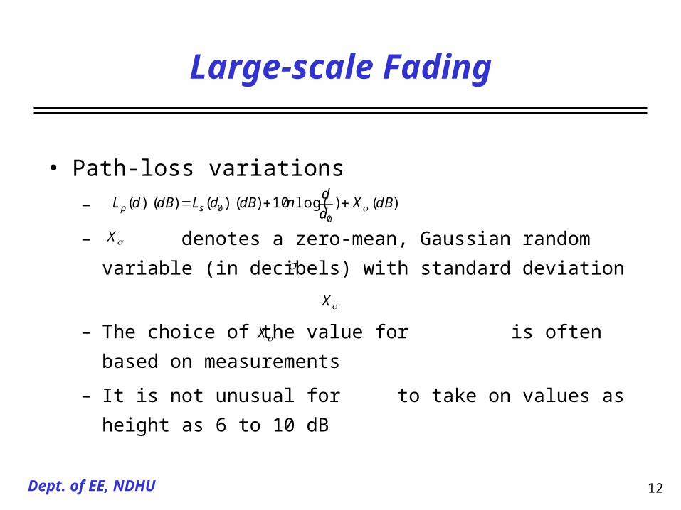
• Path-loss variations
–
– denotes a zero-mean, Gaussian random variable (in decibels)
with standard deviation
– The choice of the value for is often based on measurements
– It is not unusual for to take on values as height as 6 to 10 dB
X
)()log(10)( )()( )(0
0 dBXd
dndBdLdBdL sp
X
X

13Dept. of EE, NDHU
Path-Loss Measurements in German Cities

14Dept. of EE, NDHU
Small-Scale Fading
• Assumptions
– Antenna remains within a limited trajectory, so that the effect of large-scale
fading is a constant
– Antenna is traveling and there are multiple scatter paths with a time-variant
propagation delay , and a time-variant multiplicative factor
– Noise is free
• Derive the bandpass signal within a small-scale fading channel
)(tn )(tn
)()()(2
)]([2
)()()()(
is signal baseband equivalent
)})]([)(Re({)(
)]([)()(
tj
n
tnjn
n
tncfjn
tntcfj
nnn
nnn
etetettz
ettgttr
ttsttr

15Dept. of EE, NDHU
Multi-path Reflected Signal On A Desired Signal
)()()()( tnjnnn ettjytx
pdfRician otherwise 0
0,0for )(]2
)(exp[)(
)()()(
020
02
220
20
0
220
ArAr
IArr
rp
tytxtr rr
order zero and kindfirst theoffunction Bessel modified theis )( and
component signal faded-non theof magnitudepeak thedenotes
0 I
A

16Dept. of EE, NDHU
Multi-path Reflected Signal Without A Desired Signal
pdfRayleigh otherwise 0
0for ]2
exp[)( 02
20
20
0
rrr
rp
•As the magnitude of the line-of sight component approaches zero,
the Rician pdf approaches a Rayleigh pdf. That is,

17Dept. of EE, NDHU
Response of A Multi-path Channel As A Function of Position
0.4 is positions antennabetween interval The

18Dept. of EE, NDHU
Small-scale Fading: Mechanisms, Degradations And Effects

19Dept. of EE, NDHU
Signal Time-Spreading
• Signal time-spreading viewed in the Time-Delay Domain
– Wide-sense stationary uncorrelated scattering (WSSUS) model
– The model treats signal arriving at a receive antenna with different delays as
uncorrelated
– Multi-path-intensity profile describes the average received signal power as a function
of the time delay
– Multi-path-intensity profile usually consists multiple discrete multi-path components
– The time between the first and the last received component represents the maximum
excess delay
– The threshold level relative to the strongest component might be chosen 10 dB or 20
dB

20Dept. of EE, NDHU
Signal Time-Spreading
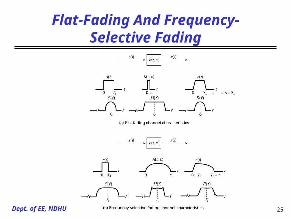
• Degradation Categories viewed in the Time-Delay Domain
– Frequency selective fading
+ The maximum excess delay time is larger than the symbol time
+ The received multi-path components of a symbol extend beyond the symbol’s duration
+ Yield inter-symbol interference (ISI) distortion that is the same as the ISI caused by an electronic filter
+ Mitigate the ISI distortion is possible because many of the multi-path components are resolvable by the recei
ver
– Frequency non-selective fading or flat fading
+ The maximum excess delay time is smaller than the symbol time
+ All of the received multi-path components of a symbol arrive within a symbol time
+ No ISI induces
+ Performance degradation due to the un-resolvable phasor components can add up destructively to reduce SN
R
+ Signal diversity and using error-correction coding is the most efficient way to improve the performance
sm TT
sm TT

21Dept. of EE, NDHU
Signal Time-Spreading
• Signal time-spreading viewed in the frequency Domain
– Obtain the Fourier transform of
+ Correlation between the channel’s response to two signals as a function of the frequency diff
erence between the two signals
– Coherent bandwidth
+ A statistical measure of the range of the frequencies over which the channel passes all spectr
al components with approximately equal gain and linear phase
+ Approximately, the coherent bandwidth and the excess delay spread are reciprocally
related
+ The relationship between the coherent bandwidth and the root-mean-squared (rms) delay spr
ead depends on the correlation of the channel’s frequency response (ex. while the
correlation of at least 0.5)
)(S )(function n correlatiofrequency -spaced fR
0f
mT0f
mTf /10
276.0
0 f

22Dept. of EE, NDHU
Relationships Among The Channel Correlation Functions

23Dept. of EE, NDHU
Frequency Response And Transmitted Signal
Wf 0
Wf 0
center) band signalat occursfunction
transfer-frequency Channel of (Null
0 Wf
24Dept. of EE, NDHU
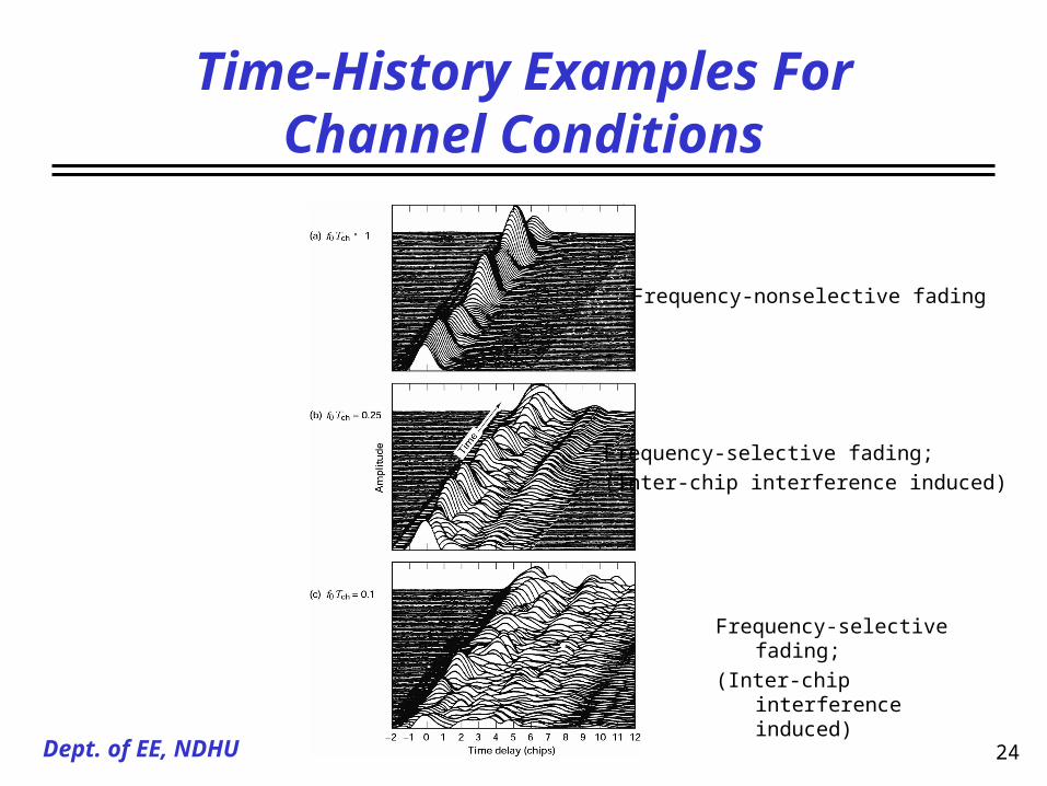
Time-History Examples For Channel Conditions
Frequency-nonselective fading
Frequency-selective fading;
(Inter-chip interference induced)
Frequency-selective fading;
(Inter-chip interference induced)
25Dept. of EE, NDHU
Flat-Fading And Frequency-Selective Fading

26Dept. of EE, NDHU
Time Variance Of The Channel
• Time variance viewed in the time Domain
– Space-time correlation function
+ Correlation between the channel’s response to a sinusoidal sent at time t1 and the
channel’s response to a sinusoidal sent at time t2
– Coherent time
+ A measure of the expected time duration over which the channel’s response is ess
entially invariant
+ Provide knowledge about the fading rapidity of the channel
+ Using the dense-scatter channel model, the normalized correlation function with a
n unmodulated CW signal is described by
/2 and , traverseddistance theis
function Besselorder -zero theis )( where, )()( 00
ktV
JtkVJtR
27Dept. of EE, NDHU
Degradation Categories Viewed in Time Domain
• Fast fading
– The channel coherence time is less than the time duration of a transmission symbol
– Channel will change several times during the time span of a symbol
– Mobile moves fast
– Result in an irreducible error rate
– It is difficult to adequately design a match filter
• Slow fading
– Symbol period is less than the coherence time
– On can expect the channel state to virtually remain unchanged during the symbol time
– Mobile moves slowly
– The primary degradation in a slow-fading, as with flat-fading, is the loss in SNR

28Dept. of EE, NDHU
Time Variance Viewed In Doppler-shift Domain
• Signal spectrum at the antenna terminal
– The spectrum shape is the result of the dense-scatter channel model
– The maximum Doppler-shift is
– is the Fourier transform of
– Yields knowledge about the spectral spreading of a transmitted sinusoidal in the Doppler-shift domain
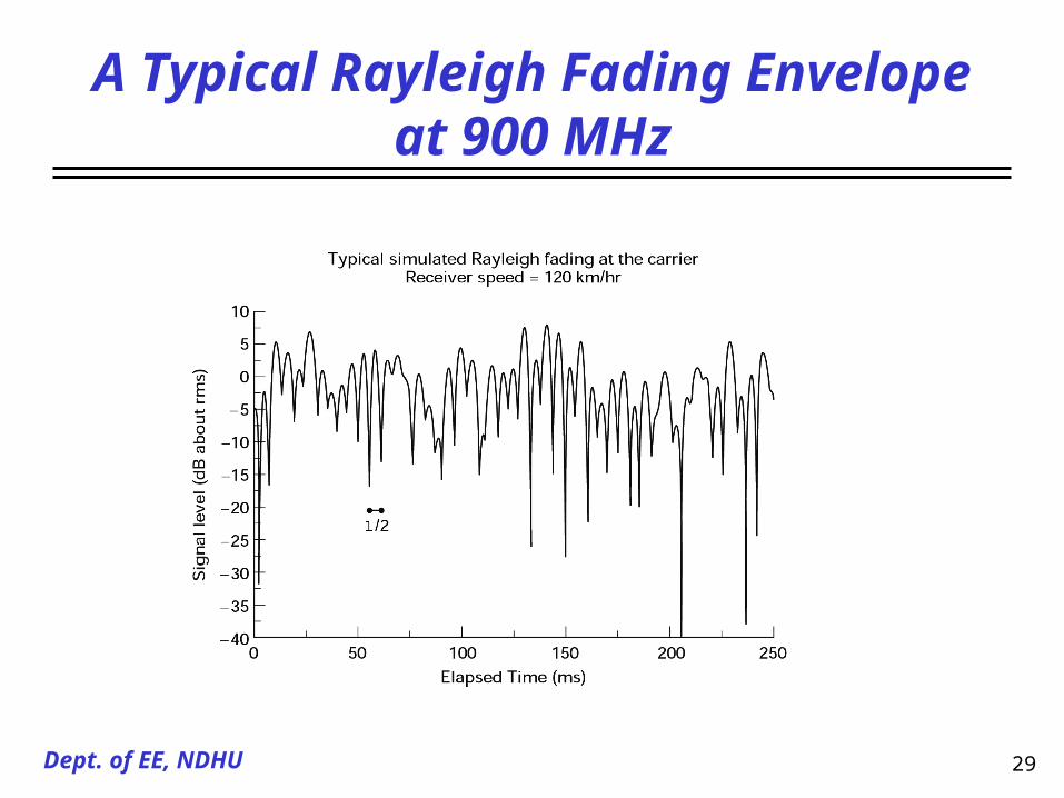
• Doppler spread and coherence time are reciprocally related
– example: the velocity=120km/hr, and the carrier frequency=900MHz, then the fading rate is approximately 100Hz
and the coherence time is approximately 5 ms
dd
d
cd
fvf
ffv
f
vS
re whe
)(1
1)(
2
V
fd
)(vS )( tR
fd 0T
dd ffT
423.0
16
920
29Dept. of EE, NDHU
A Typical Rayleigh Fading Envelope at 900 MHz

30Dept. of EE, NDHU
Spectral Broadening In Keying A Digital Signal

31Dept. of EE, NDHU
Combination of Specular And Multi-Path Components

32Dept. of EE, NDHU
Error Performance for pi/4 DQPSK
33Dept. of EE, NDHU
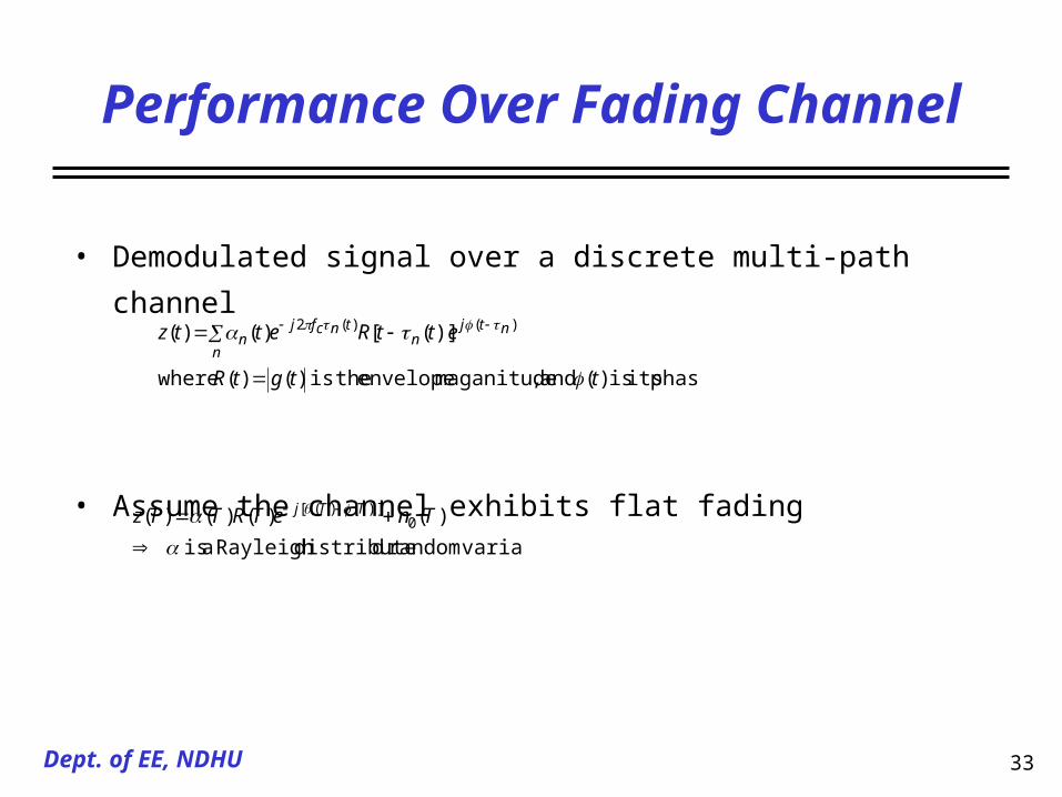
Performance Over Fading Channel
• Demodulated signal over a discrete multi-path channel
• Assume the channel exhibits flat fading
phase its is )( and ,maganitude envelope theis )()( where
)]([)()( )()(2
ttgtR
ettRettzn
ntjn
tncfjn
variablerandom ddistributeRayleigh a is
)()()()( 0)]()([
TneTRTTz TTj

34Dept. of EE, NDHU
Performance Over A Slow Rayleigh Fading Channel

35Dept. of EE, NDHU
Error Performance: Good, Bad, Awful

36Dept. of EE, NDHU
Mitigate The Degradation Effects of Fading
37Dept. of EE, NDHU
Mitigation To Combat Frequency Selective Fading
• Equalization can mitigate the effects of channel-induced ISI
• Can help modify the system performance from “awful” to
“bad”
• Gather the dispersed symbol energy back into its original
time interval
• Equalizer is an inverse filter of the channel
• Equalizer filter must also change or adapt to the time-
varying channel characteristics

38Dept. of EE, NDHU
Mitigation To Combat Frequency Selective Fading
• Decision feedback equalizer (DFE)
– Once an information symbol has been detected, the ISI that it induces on fut
ure symbols can be estimated and subtracted before the detection of subsequ
ent symbols
• Maximum-likelihood sequence estimation (MLSE) equalizer
– Test all the possible data sequence and choose the most probable of all the c
andidates
– Implemented by using Viterbi decoding algorithm
– MLSE is optimal in the sense that it minimizes the probability of a sequence
error

39Dept. of EE, NDHU
Mitigation To Combat Frequency Selective Fading
• Direct-sequence spread spectrum (DS/SS) techniques
– Mitigate frequency-selective ISI distortion
– Effectively eliminate the multi-path interference by its code correlation receiver
– RAKE receiver coherently combines the multi-path energy
• Frequency hopping spread spectrum (FH/SS) technique
– Frequency diversity
• OFDM
– Avoid the use of equalizer by lengthening the symbol duration
– DAB, DVBT systems
• Pilot signal
40Dept. of EE, NDHU
Mitigation To Combat Fast Fading
• Robust modulation techniques
– Non-coherent scheme or differential scheme
– Not require phase tracking
• Increase the symbol rate by adding the signal redundancy
• Error-correction coding

41Dept. of EE, NDHU
Mitigation To Combat Loss in SNR
• Diversity methods to move the performance “bad” to “good”
– “Diversity” is used to provide the receiver with uncorrelated renditions of the signal of
interest
• Time diversity
– Transmit the signal on L different time slots with time separation of at least T0
– Interleaving with coding technique
• Frequency diversity
– Transmit the signal on L different carriers with frequency separation of at least f0
– The signal bandwidth W is expanded and the frequency diversity order is achieved by
W/f0
– There is the potential for the frequency-selective fading unless the equalizer is used

42Dept. of EE, NDHU
Mitigation to Combat Loss in SNR
• Spread-spectrum systems
• Frequency hopping spread spectrum
• Spatial diversity
– Multiple receive antennas, separated by a distance of at least 10
wavelengths
– Coherently combine all the antenna outputs
• Polarization diversity
• Space-time coding technique

43Dept. of EE, NDHU
Diversity Techniques
• The goal is to utilize additional independent (or at least uncorrelated) signal paths to
improve the received SNR
• Error performance improvement
Mi
MM
ii
iii
ii
i
i
b
bBBB
p
p
ddpp
p
Mi
NExx
xp
NExxxPdxxpxPP
)]exp(1[1)(
)]exp(1[),(
)exp(1)exp(1
)()(
0 , )exp(1
)(
SNR sinstanteouan has ,,,2,1 branch,diversity each If
SNR averaged theis / ,0 ),exp(1
)(
ddistribute squared-chi is d,distributeRayleigh is
,/ and SNRat y probabiliterror -bit theis )( where,)()(
,,21
00
02
2
02
0

44Dept. of EE, NDHU
Diversity Combining Techniques
• Selection
– The sampling of M antenna signals and sending the largest one to the demodulator
– Relatively easy to implement
– Not optimal
• Feedback
– The M signals are scanned in a fixed sequence until one that exceeds a given threshold is found
– The error performance is somewhat inferior to the other methods
– Feedback diversity is quite simple to implement
• Maximal ratio combining
– The signal are weighted according to their individual SNR
– The individual signals must be co-phase before being summed
– Produce an average SNR by
MM
i
M
iiM
11
45Dept. of EE, NDHU
Modulation Types For Fading Channels
• Amplitude-based signal modulation (e.g. QAM) is vulnerabl
e to performance degradation in a fading channel
• Frequency or phase-based modulation is the preferred choice
in a fading channel
• The use of MFSK is more useful than binary signal
• In a slow Rayleigh fading channel, binary DPSK performs w
ell

46Dept. of EE, NDHU
Interleaver
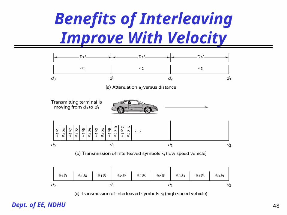
• The primary benefit of an interleaver is to provide time diversity
• The larger the time span, the greater chance that of achieving effective diversity
• The interleaver time span is usually larger than the conerence time
• In a real-time communication system, too large interleaver time ( e.g.
) is not feasible since the inherent time delay would be excessive
• The interleaver provides no benefit against multi-path unless there is motion bet
ween the transmitter and the receiver
• As the motion increases in velocity, so does the benefit of a given interleaver to t
he error performance
10000/ 0 TTIL
ILT 0T

47Dept. of EE, NDHU
Error Performance For Various Interleaver Spans
0T
48Dept. of EE, NDHU
Benefits of Interleaving Improve With Velocity

49Dept. of EE, NDHU
Required Eb/N0 Versus Speed

50Dept. of EE, NDHU
Key Parameters for Fading Channels
• Fast-fading distortion
–
– Mitigation
+ Choose a modulation/demodulation technique that is most robust under fast-fadin
g channel
+ For example, avoiding scheme that require PLLs
+ Sufficient redundancy that the symbol rate exceeds the fading rate and does not e
xceed the coherent bandwidth
+ Pilot signal
+ Error-correction coding
dfWf 0

51Dept. of EE, NDHU
Key Parameters for Fading Channels
• Frequency-selective fading distortion
–
– Mitigation
+ Adaptive equalization, spread-spectrum, OFDM
+ Viterbi algorithm
+ Once the distortion effects have been reduced, diversity technique, error-correctio
n coding should be introduced to approach AWGN performance
• Fast-fading and frequency-selective fading distortion
+
dfWf 0
dfWf 0

52Dept. of EE, NDHU
Applications
• Viterbi equalizer as applied to GSM
msV
T 32/
0

53Dept. of EE, NDHU
Applications
• Viterbi equalizer as applied to GSM

54Dept. of EE, NDHU
Applications
• RAKE receiver as applied to DS spread-spectrum systems