depth-based image registration - dapeng oliver wu's home page
TRANSCRIPT

Depth-Based Image Registration
Bing Han, Christopher Paulson, Jiangping Wang, and Dapeng WuDepartment of Electrical and Computer Engineering
University of Florida Gainesville, FL 32611Correspondence author: Prof. Dapeng Wu, [email protected], http://www.wu.ece.ufl.edu
ABSTRACTImage registration is a fundamental task in computer vision because it can significantly contribute to high-level computervision and benefit numerous practical applications. Though a lot of image registration techniques exist in literature, thereis still a significant amount of research to be conducted because there are a lot of issues that need to be solved such asthe parallax problem. The traditional image registration algorithms suffer from the parallax problem due to their underlingassumption that the scene can be regarded approximately planar which is not satisfied in the case of large depth variationin the images with high-rise objects. With regard to the the parallax problem, a new strategy is proposed by leveragingthe depth information via 3D reconstruction. One novel idea is to recover the depth in the image region with high-riseobjects to build accurate transform function for image registration. Our method mitigates the parallax problem and canachieve robust registration results, which is validated by our experiments. Our algorithm is attractive to numerous practicalapplications.
Keywords: 3D reconstruction, image registration, depth estimation, parallax problem
1. INTRODUCTIONImage registration is a fundamental task in image processing and computer vision which matches two or more imagestaken at different times and different viewpoints, by geometrically aligning reference and sensed images. There has beena broad range of techniques developed over the years in literature. A comprehensive survey of image registration methodswas published in 1992 by Brown,1 including many classic methods still in use. Due to the rapid development of imageacquisition devices, more image registration techniques emerged afterwards and were covered in another survey2 publishedin 2003. Different applications due to distinct image acquisition require different image registration techniques. In general,manners of the image acquisition can be divided into three main groups:
• Different viewpoints (multiview analysis). Images of the same scene are acquired from different viewpoints. The aimis to gain a larger 2D view or a 3D representation of the scanned scene.
• Different times. Images of the same scene are acquired at different times, often on regular basis, and possibly underdifferent conditions. The aim is to find and evaluate changes in the scene which appeared between the consecutiveimage acquisitions.
• Different sensors. Images of the same scene are acquired by different sensors. The aim is to integrate the informationobtained from different source streams to gain more complex and detailed scene representation.
Due to the diversity of images to be registered and various types of degradations, it is impossible to design a universalmethod applicable to all registration tasks. Every method should take into account not only the assumed type of geometricdeformation between the images but also the radiometric deformations and noise corruption, required registration accuracyand application-dependent data characteristics. Nevertheless, the majority of the registration methods consists of the fol-lowing four steps: feature detection, feature matching, transform model estimation, image resampling and transformation.
A widely used feature detection method is corner detection. Kitchen and Rosenfeld3 proposed to exploit the second-order partial derivatives of the image function for corner detection. Dreschler and Nagel4 searched for the local extremaof the Gaussian curvature. However, corner detectors based on the second-order derivatives of the image function aresensitive to noise. Thus Forstner5 developed a more robust, although time consuming, corner detector, which is based onthe first-order derivatives only. The reputable Harris detector6 also uses first-order derivatives for corner detection.

Feature matching includes area-based matching and feature-based matching. Classical area-based method is cross-correlation (CC)7 exploit for matching image intensities directly. For feature-based matching, Goshtasby8 described theregistration based on the graph matching algorithm. Clustering technique, presented by Stockman et al.,9 tries to matchpoints connected by abstract edges or line segments.
After the feature correspondence has been established the mapping function is constructed. The mapping functionshould transform the sensed image to overlay it over the reference image.
Finally interpolation methods such as nearest neighbor function, bilinear, and bicubic functions are applied to the outputof the registered images.
The prevailing image registration methods, such as the algorithm of Davis and Keck,10, 11 assume all the feature pointsare coplanar and build a homography transform matrix to do registration. The advantage is that they have low computationalcost and can handle planar scenes conveniently; however, with the assumption that the scenes are approximately planar,they are inappropriate in the registration applications when the images have large depth variation due to the high-riseobjects, known as the parallax problem. Parallax is an apparent displacement of difference of orientation of an objectviewed along two different lines of sight, and is measured by the angle or semi-angle of inclination between those twolines. Nearby objects have a larger parallax than further objects when observed from different positions. Therefore, as theviewpoint moves side to side, the objects in the distance appear to move slower than the objects close to camera.
In this paper, we propose a depth based image registration algorithm by leveraging the depth information. Our methodcan mitigate the parallax problem caused by high-rise scenes in the images by building accurate transform function betweencorresponding feature points in multiple images. Given an image sequence, we first select a number of feature points andthen match the features in all images. Then we estimate the depth of each feature point from feature correspondences.With the depth information, we can project the image in 3D instead of using a homography transform. Further more, fastand robust image registration algorithm can be achieved by combining the traditional image registration algorithms anddepth based image registration method proposed in this paper. The idea is that we first compute the 3D structure of a sparsefeature points set and then divide the scene geometrically into several approximately planar regions. For each region, wecan perform a depth based image registration. Accordingly, robust image registration is achieved.
The remainder of this paper is organized as follows. Section 2 presents the 3D reconstruction algorithm on which ourexperiments are based. In Section 3, we describe our depth-based image registration algorithm from theoretical aspectsto explain why it can mitigate the parallax problem. Section 4 compares our algorithm with the algorithm of Davis andKeck10 on the same video sequence. We conclude the paper in Section 5.
2. 3D RECONSTRUCTION FROM VIDEO SEQUENCESHere, we simply introduce the 3D reconstruction algorithm proposed in Ma et. al’s book12 on which our experimentsare based. When developing a stereo vision algorithm for registration, the requirements for accuracy vary from those ofstandard stereo algorithms used for 3D reconstruction. For example, a multi-pixel disparity error in an area of low texture,such as a white wall, will result in significantly less intensity error in the registered image than the same disparity error ina highly textured area. In particular, edges and straight lines in the scene need to be rendered correctly.
The 3D reconstruction algorithm is implemented using the following steps.12 First, geometric features are detectedautomatically in each individual images. Secondly, feature correspondence is established across all the images. Then thecamera motion is retrieved and the camera is calibrated. Finally the Euclidean structure of the scene is recovered.
2.1. Feature selectionThe first step in 3D reconstruction is to select candidate features in all images for tracking across different views. Ma etal.12 use point feature in reconstruction which is measured by Harris’ criterion,
C(x) = det(G) + k × trace2(G), (1)
where x = [x, y]T is a candidate feature, C(x) is the quality of the feature, k is a pre-chosen constant parameter and G isa 2× 2 matrix that depends on x, given by
G =[ ∑
W (x) I2x
∑W (x) IxIy∑
W (x) IxIy
∑W (x) I2
y
](2)

where W (x) is a rectangular window centered at x and Ix and Iy are the gradients along the x and y directions which canbe obtained by convolving the image I with the derivatives of a pair of Gaussian filters. The size of the window can bedecided by the designer, for example 7× 7. If C(x) exceeds a certain threshold, then the point x is selected as a candidatepoint feature.
2.2. Feature correspondenceOnce the candidate point features are selected, the next step is to match them across all the images. In this subsection, weuse a simple feature tracking algorithm based on a translational model.
We use the sum of squared differences (SSD)13 as the measurement of the similarity of two point features. Then thecorrespondence problem becomes looking for the displacement d that satisfies the following optimization problem:
mind
.=∑
x∈W (x)
[I2(x + d)− I1(x)]2 (3)
where d is the displacement of a point feature of coordinates x between two consecutive frames I1 and I2. Lucas andKanade also give the close form solution of 3
d = −G−1b (4)
where
b .=
[∑W(x)
IxIt∑W(x)
IyIt
](5)
G is the same matrix we used to compute the quality of the candidate point feature in Eq. 1, and It.= I2 − I1.
2.3. Estimation of camera motion parametersIn this subsection, we recover the projective structure of the scene from the established feature correspondence. We willfollow the notation used in Ma et al.’s book.12 For the detail of the proof of this algorithm, please refer to the reference.
The reconstruction algorithm is based on a perspective projection model with a pinhole camera. Suppose we have ageneric point p ∈ E3 with coordinates X = [X,Y, Z, 1]T relative to a world coordinate frame. Given two frames of onescene which is related by a motion g = (R, T ), the two image projection point x1 and x2 are related as follows:
λ1x′1 = Π1Xp, λ2x′2 = Π2Xp, (6)
where x′ = [x, y, 1]T is measured in pixels, λ1 and λ2 are the depth scale of x1 and x2, Π1 = [K, 0] and Π2 = [KR,KT ]are the camera projection matrices and K is the camera calibration matrix. In order to estimate λ1, λ2, Π1 and Π2, weneed to introduce the epipolar constraint. From Eq. 6, we have
x′T2 K−T TRK−1x′1 = 0. (7)
The fundamental matrix is defined as:F
.= K−T TRK−1. (8)
With the above model, we could estimate the fundamental matrix F via the Eight-point algorithm.12 Then we coulddecompose the fundamental matrix to recover the projection matrices Π1 and Π2 and the 3D structure. We only give thesolution here by canonical decomposition:
Π1p = [I, 0], Π2p = [(T ′)T F, T ′], λ1x′1 = Xp, λ2x′2 = (T ′)T FXp + T ′. (9)
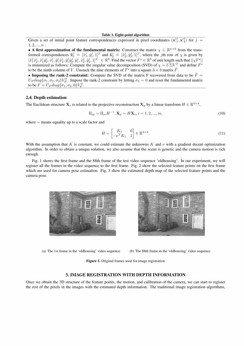
Table 1. Eight-point algorithmGiven a set of initial point feature correspondences expressed in pixel coordinates (x′j1,x
′j2) for j =
1, 2, ..., n :• A first approximation of the fundamental matrix: Construct the matrix χ ∈ Rn×9 from the trans-formed correspondences xj
1.= [xj
1, yj1, 1]T and xj
2.= [xj
2, yj2, 1]T , where the jth row of χ is given by
[xj1x
j2, x
j1y
j2, x
j1, y
j1x
j2, y
j1y
j2, y
j1, x
j2, y
j2, 1]T ∈ R9. Find the vector F s ∈ R9 of unit length such that ||χF s||
is minimized as follows: Compute the singular value decomposition (SVD) of χ = UΣV T and define F s
to be the ninth column of V . Unstack the nine elements of F s into a square 3× 3 matrix F .• Imposing the rank-2 constraint: Compute the SVD of the matrix F recovered from data to be F =UF diag{σ1, σ2, σ3}V T
F . Impose the rank-2 constraint by letting σ3 = 0 and reset the fundamental matrixto be F = UF diag{σ1, σ2, 0}V T
F .
2.4. Depth estimationThe Euclidean structure Xe is related to the projective reconstruction Xp by a linear transform H ∈ R4×4,
Πip ∼ ΠieH−1,Xp ∼ HXe, i = 1, 2, ..., m, (10)
where ∼ means equality up to a scale factor and
H =[
K1 0−νT K1 1
]∈ R4×4. (11)
With the assumption that K is constant, we could estimate the unknowns K and ν with a gradient decent optimizationalgorithm. In order to obtain a unique solution, we also assume that the scene is generic and the camera motion is richenough.
Fig. 1 shows the first frame and the 88th frame of the test video sequence ‘oldhousing’. In our experiment, we willregister all the frames in the video sequence to the first frame. Fig. 2 show the selected feature points on the first framewhich are used for camera pose estimation. Fig. 3 show the estimated depth map of the selected feature points and thecamera pose.
(a) The 1st frame in the ‘oldhousing’ video sequence (b) The 88th frame in the ‘oldhousing’ video sequence
Figure 1. Original frames used for image registration
3. IMAGE REGISTRATION WITH DEPTH INFORMATIONOnce we obtain the 3D structure of the feature points, the motion, and calibration of the camera, we can start to registerthe rest of the pixels in the images with the estimated depth information. The traditional image registration algorithms,

1
23
4
567
89 10
11
12
13
1415
16
1718
19
20
21
22
2324
25
26
2728
29
30
31
32
33
3435
36
37
38
39
40
41
42
43
44 45
46
47
48
49
50
51
52
53
54
5556
57
58
59 60
61
62
63 64
65
66
67
68
69
70
71
72
Figure 2. The feature points selected for depth estimation on the 1st frame.
such as the algorithm of Davis and Keck,10, 11 try to register the two images by computing the homography matrix Hbetween corresponding feature points. The limit of this algorithm is that they assume all the points in the physical worldare coplanar or approximately coplanar, which is not true with high-rise scenes. In order to mitigate this problem, wepropose a novel algorithm which first segment the image geometrically and then perform the registration to each regionwith depth estimation.
3.1. Geometrical segmentationIn order to perform the geometrical segmentation, the most intuitive method is to obtain the dense surface model of thescene and then segment the surface into several regions based on the depth of the points. However, we need to know thecorrespondence for almost all the pixels to compute the dense surface model, which means we need to know all the pixelcorrespondence before the registration. In order to avoid this dilemma, we will not use the traditional 3D reconstructionalgorithm to estimate the dense surface model. Instead, we directly segment the scene into several regions by clusteringthe sparse 3D points set that we obtained in Section 2. With the assumption that each segment region of the scene isapproximately coplanar in the physical world, we could easily estimate the plane model and project the 3D plane onto theimage frames. Comparing the assumption that the whole scene is coplanar in the physical world used in the traditionalimage registration algorithms, this assumption is valid in most circumstances.
There are a lot of algorithms for data clustering. The most famous hard-clustering algorithm is k-means.14 The k-means algorithm assigns each data point to the cluster whose centroid is nearest. Here, we use the distance to a 3D plane inthe physical world as the measurement. For each cluster, we could choose the plane that has the smallest sum of distanceof all the data points in the cluster.
3.2. Depth estimationHere, we only consider two images. Suppose for the first image, we have the 3D point set Xj
e, j = 1, 2, ..., n which couldbe divided into three clusters,Xe1, Xe2, Xe3. For each cluster, there are at least three non-collinear points. Then we couldhave the plane model for this cluster. Let’s take the example of Xe1, suppose there are m points in the cluster and we havethe plane model as follows:
A · p = 1. (12)

−100 0 100−500500
50
100
150
200
250
300
350
400
450
y
3672
342527
65
4038241417633
1924111
53720211660
515623
472612
x
8101518
Euclidean reconstruction from multiple views
9644939
31
59433261486866453054692522447157
5250703437
29586255
1335
6367
412846
z
Figure 3. The estimated depth map and camera pose for the selected feature points of the 1st and 88th frames.
where A = [Xie1], i = 1, ..., m and p = [a, b, c]T is the plane parameter.
Given an arbitrary point xi = [xi, yi]T measured in pixels in the first cluster, we could estimate it’s depth scale λi bysolving the following equation.
λix′i = H−11 Π1Xi
e. (13)
where x′i = [xi, yi, 1]T , H−11 and Π1 are estimated in Section 2. In Eq. 13, only λi is unknown and with the constraint on
Xie with Eq. 12, we could easily get the value of λi.
Then, with Π1 = [I, 0], we could have Xip = [λi
1xi, λi
1yi, λi
1, 1]. from Eq. 6, we can get the relation between twoimage projection point xi
1 and xi2 as follows:
xi2′ = Π2Xi
p. (14)
where xi2′ = [λi
2xi2, λ
i2y
i2, λ
i2]. We could then get the position of the corresponding point xi
2 = [xi2, y
i2] in the second
image.
4. EXPERIMENTAL RESULTSThe data includes a sequence of 88 images captured from one camera. We first select 72 feature points in the first imageand then find the corresponding feature points in the rest of the images. The depth estimates of these points are calculatedby the algorithm introduced in Section 2.
In our experiment, we regard the first image’s local coordinate system as world coordinate system so the first imagecan be viewed as a reference image. Then the rest of the images are registered to the reference image. We also applied thealgorithm of Davis and Keck10 to accomplish the same task for comparison purpose.
Fig. 1 is the 1st frame and the 88th frame in the test image sequence. Fig. 4 is the registration result using our algorithmand Fig. 5 is the output of the algorithm of Davis and Keck.10 Fig. 6 shows the difference image between the registeredimage and the first image using our algorithm and Fig. 7 shows the difference image from the algorithm of Davis andKeck.10 We can see that our result can mitigate the parallax problem since the roof and wall corners are registered
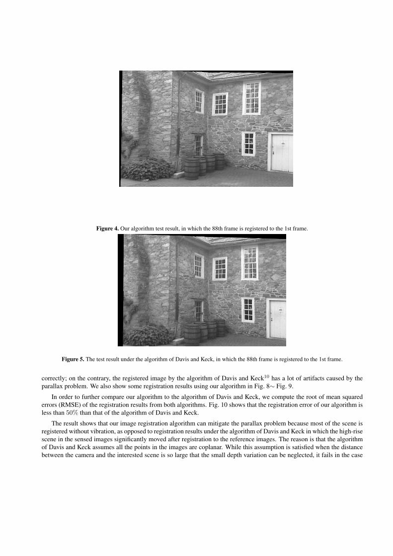
Figure 4. Our algorithm test result, in which the 88th frame is registered to the 1st frame.
Figure 5. The test result under the algorithm of Davis and Keck, in which the 88th frame is registered to the 1st frame.
correctly; on the contrary, the registered image by the algorithm of Davis and Keck10 has a lot of artifacts caused by theparallax problem. We also show some registration results using our algorithm in Fig. 8∼ Fig. 9.
In order to further compare our algorithm to the algorithm of Davis and Keck, we compute the root of mean squarederrors (RMSE) of the registration results from both algorithms. Fig. 10 shows that the registration error of our algorithm isless than 50% than that of the algorithm of Davis and Keck.
The result shows that our image registration algorithm can mitigate the parallax problem because most of the scene isregistered without vibration, as opposed to registration results under the algorithm of Davis and Keck in which the high-risescene in the sensed images significantly moved after registration to the reference images. The reason is that the algorithmof Davis and Keck assumes all the points in the images are coplanar. While this assumption is satisfied when the distancebetween the camera and the interested scene is so large that the small depth variation can be neglected, it fails in the case

Figure 6. The difference image between the registered 88th image (using our algorithm) and the 1st image.
of high-rise scene. Therefore, depth information should be used to accomplish the registration for this specific high-riseregion of the images.
Finally, we would like to point out that the algorithm of Davis and Keck10 assumes a planar registration. Their schemewas designed for use with high-altitude aerial imagery where planar transformations are fairly good approximations. Fur-thermore, their scheme uses RANSAC to remove poor matching points during the computation. This can help to dealwith some depth discontinuities that may be present in the high-altitude aerial images. In our experiments, the test imagescontain salient 3D scenes; these images are out of the domain for the algorithm of Davis and Keck. This is the reason whythe algorithm of Davis and Keck does not perform well.
5. CONCLUSIONIn this paper, we propose a new 2D image registration method by leveraging depth information. While traditional imageregistration algorithms fail to register high-rise scene accurately because the points cannot be assumed to be simply planar,our image registration algorithm can mitigate the parallax problem.
Our future works include:
• Develop a robust 3D model based on the state-of-the-art depth estimate algorithm1516 given a video sequence. Thereliability of the depth estimates is crucial to depth-based registration algorithm; therefore, the highly robust 3Dreconstruction technique is required to implement our algorithm. Up to now, most recent depth recovery algorithmsreported in the literature claim to recover consistent depth from some challenging video sequences15.16 We canapply or modify this state-of-the-art depth map recovery method to develop depth-based image registration algorithm.
• Combine depth-based image registration method with traditional algorithms. In other words, we can use depthinformation to register high-rise region while applying traditional registration algorithm for other planar region ofthe image. The purpose is to tradeoff between the accuracy of the registration and the high computational costintroduced by 3D reconstruction. The combined algorithm thus can enjoy both the high efficiency of the traditionalalgorithm and the high robustness of the depth-based registration method.
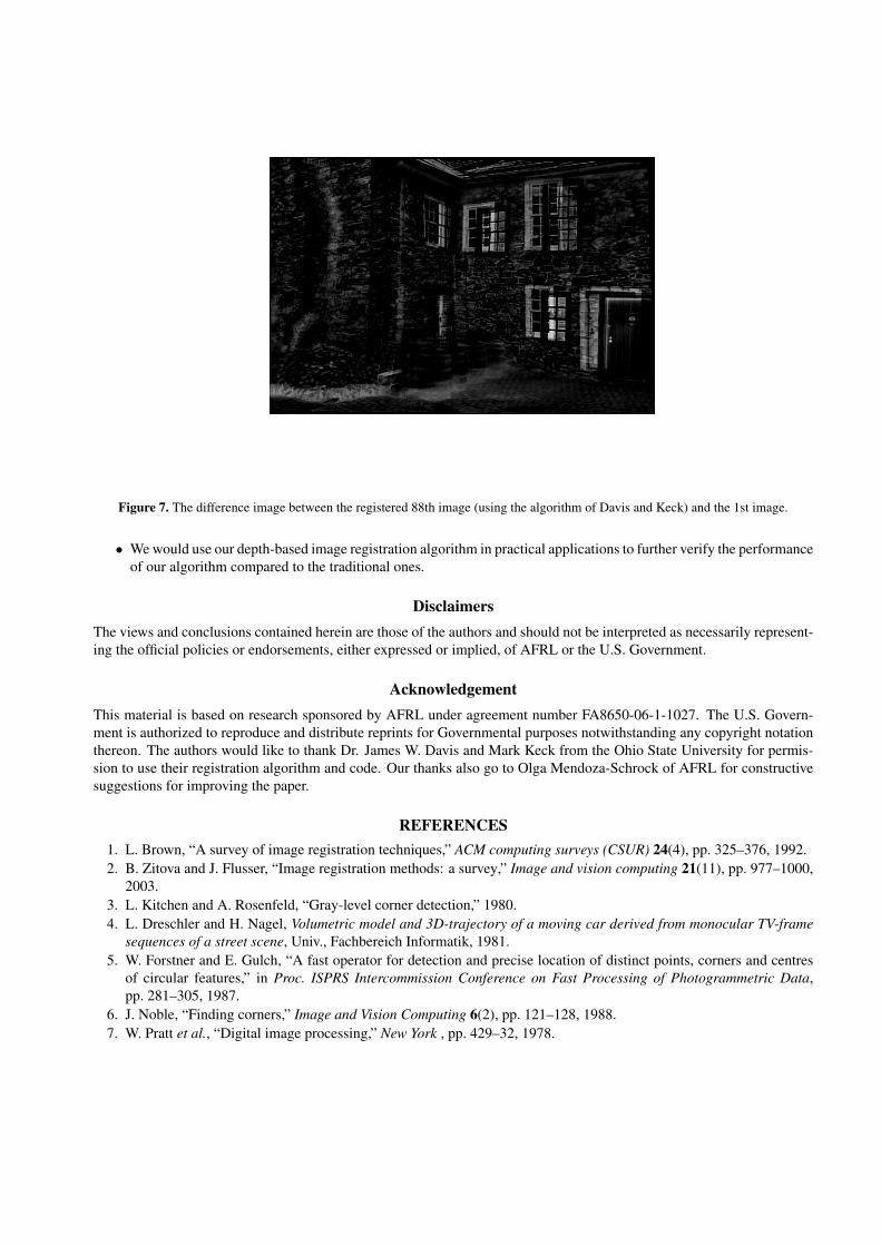
Figure 7. The difference image between the registered 88th image (using the algorithm of Davis and Keck) and the 1st image.
• We would use our depth-based image registration algorithm in practical applications to further verify the performanceof our algorithm compared to the traditional ones.
DisclaimersThe views and conclusions contained herein are those of the authors and should not be interpreted as necessarily represent-ing the official policies or endorsements, either expressed or implied, of AFRL or the U.S. Government.
AcknowledgementThis material is based on research sponsored by AFRL under agreement number FA8650-06-1-1027. The U.S. Govern-ment is authorized to reproduce and distribute reprints for Governmental purposes notwithstanding any copyright notationthereon. The authors would like to thank Dr. James W. Davis and Mark Keck from the Ohio State University for permis-sion to use their registration algorithm and code. Our thanks also go to Olga Mendoza-Schrock of AFRL for constructivesuggestions for improving the paper.
REFERENCES1. L. Brown, “A survey of image registration techniques,” ACM computing surveys (CSUR) 24(4), pp. 325–376, 1992.2. B. Zitova and J. Flusser, “Image registration methods: a survey,” Image and vision computing 21(11), pp. 977–1000,
2003.3. L. Kitchen and A. Rosenfeld, “Gray-level corner detection,” 1980.4. L. Dreschler and H. Nagel, Volumetric model and 3D-trajectory of a moving car derived from monocular TV-frame
sequences of a street scene, Univ., Fachbereich Informatik, 1981.5. W. Forstner and E. Gulch, “A fast operator for detection and precise location of distinct points, corners and centres
of circular features,” in Proc. ISPRS Intercommission Conference on Fast Processing of Photogrammetric Data,pp. 281–305, 1987.
6. J. Noble, “Finding corners,” Image and Vision Computing 6(2), pp. 121–128, 1988.7. W. Pratt et al., “Digital image processing,” New York , pp. 429–32, 1978.

Figure 8. The 37th frame in the ‘oldhousing’ video sequence.
8. A. Goshtasby and G. Stockman, “Point pattern matching using convex hull edges.,” IEEE TRANS. SYST. MAN CY-BER. 15(5), pp. 631–636, 1985.
9. G. Stockman, S. Kopstein, and S. Benett, “Matching images to models for registration and object detection viaclustering,” IEEE Transactions on Pattern Analysis and Machine Intelligence 4, pp. 229–241, 1982.
10. J. Davis and M. Keck, “OSU Registration Algorithm,” Internal Report, Ohio State University, USA .11. O. Mendoza, G. Arnold, and P. Stiller, “Further exploration of the object-image metric with image registration in
mind,” in Proceedings of the SPIE, Symposium on Multisensor, Multisource Information Fusion: Architectures, Al-gorithms, and Applications, B. V. Dasarathy, ed., 6974, pp. 697405–697405–12, April 2008.
12. Y. Ma, S. Soatto, J. Kosecka, Y. Ma, S. Soatta, J. Kosecka, and S. Sastry, An invitation to 3-D vision, Springer, 2004.13. B. Lucas and T. Kanade, “An iterative image registration technique with an application to stereo vision,” in Interna-
tional joint conference on artificial intelligence, 3, p. 3, 1981.14. S. Lloyd, “Least squares quantization in PCM,” IEEE Transactions on Information Theory 28(2), pp. 129–137, 1982.15. G. Zhang, J. Jia, T. Wong, and H. Bao, “Recovering consistent video depth maps via bundle optimization,” in IEEE
Conference on Computer Vision and Pattern Recognition, 2008. CVPR 2008, pp. 1–8, 2008.16. G. Zhang, J. Jia, T. Wong, and H. Bao, “Consistent Depth Maps Recovery from a Video Sequence,” IEEE Transac-
tions on Pattern Analysis and Machine Intelligence , pp. 974–988, 2009.
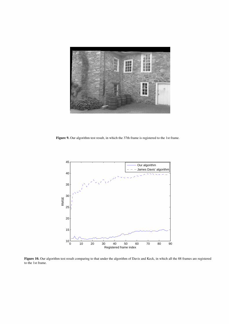
Figure 9. Our algorithm test result, in which the 37th frame is registered to the 1st frame.
0 10 20 30 40 50 60 70 80 9010
15
20
25
30
35
40
45
Registered frame index
RM
SE
Our algorithmJames Davis’ algorithm
Figure 10. Our algorithm test result comparing to that under the algorithm of Davis and Keck, in which all the 88 frames are registeredto the 1st frame.