derby products pty ltd - derby heatbanks derby installation and... · derby products pty ltd abn 81...
TRANSCRIPT
Derby Products Pty LtdABN 81 009 477 561
Unit 9/3 Lancaster Street Ingleburn NSW 2565
PO Box 568
Ingleburn NSW 1890
Free Phone : 1800 030 668
Phone : 02 9605 5119
Fax : 02 9829 2603
Email : sales@derbyproducts .com.au
www.derby -heatbanks .com.au
clean warmth. . . in perfect design
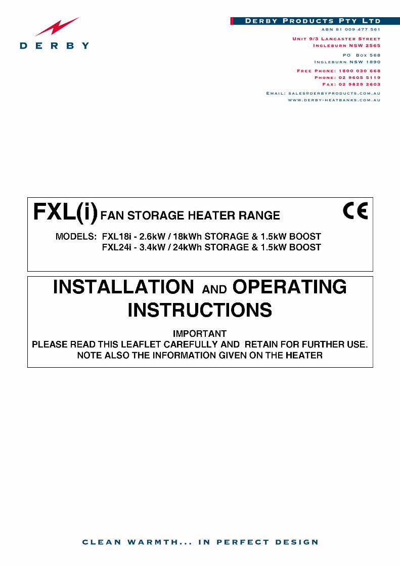
FXL(i) FAN STORAGE HEATER RANGE
MODELS: FXL18i - 2.6kW / 18kWh STORAGE & 1.5kW BOOST FXL24i - 3.4kW / 24kWh STORAGE & 1.5kW BOOST
INSTALLATION AND OPERATINGINSTRUCTIONS
IMPORTANTPLEASE READ THIS LEAFLET CAREFULLY AND RETAIN FOR FURTHER USE.
NOTE ALSO THE INFORMATION GIVEN ON THE HEATER
The Installation must be carried out by trained personnel in accordance with Australian wiring rules AS/NZS 3000.
A means for disconnection must be incorporated in the fi xed wiring in accordance with the said rules.
The heater must not be installed immediately below a fi xed socket outlet.
Do not position the heater under windows where curtains can contact the heater casing. Maintain a minimum distance of 150mm at all times between the heater and combustible materials, such as furniture and curtains.
WARNING in order to avoid overheating, do not cover the heater. Do not place objects in contact with the heater.
WARNING - THE SURFACES ON THIS HEATER CAN BE HOT.
This heater meets AS/NZS 60335 electrical safety requirements. However, any heater type becomes hot in normal operation. Care must be taken to ensure that prolonged skin contact with the heater does not occur.
WHERE YOUNG CHILDREN, INFIRM PERSONS, OR THE AGED ARE PRESENT THIS APPLIANCE MUST BE ADEQUATELY GUARDED. Contact your installer or the manufacturer for further advice.
This appliance is not intended for use by persons (including children) with reduced physical, sensory or mental capabilities, or lack of experience and knowledge, unless they have been given supervision for instruction concerning use of the appliance by a person responsible for their safety. Children should be supervised to ensure that they do not play with the appliance.
This appliance is very heavy and must be securely fi xed to a wall. DO NOT UNDER ANY CIRCUMSTANCES ATTEMPT TO MOVE OR REPOSITION THIS HEATER WITHOUT SEEKING EXPERT ADVICE.
To maintain stability, it is essential that the heater is placed on a level surface and care should be taken to avoid irregular surfaces, such as may result from carpets or tiled surrounds partially protruding under the heater.
This heater must be installed where it is impossible for switches and other controls to be touched by a person using a bath or shower.
IMPORTANT - Due to the newness of materials the heater will produce a slight smell for the fi rst few days of operation. ROOMS MUST BE WELL VENTILATED AND YOUNG CHILDREN, CAGED BIRDS, OR PERSONS WITH RESPIRATORY COMPLAINTS MUST NOT REMAIN IN CLOSE PROXIMITY TO THE HEATER DURING THE FIRST 48 HOURS OF THE COMMISSIONING PERIOD.
IF, DURING ANY REASSEMBLY OF THE HEATER, A PART OF THE THERMAL INSULATION SHOWS DAMAGE OR DETERIORATION WHICH MAY IMPAIR SAFETY, IT SHOULD BE REPLACED BY AN IDENTICAL PART.
10887
IMPORTANT WARNING – PLEASE READ
Possible problem with FXL Fans Some output fans have not worked or run slowly when first turned on due to stiff bearings.
This results in the boost element overheating and burning out when the BOOST switch is turned on.
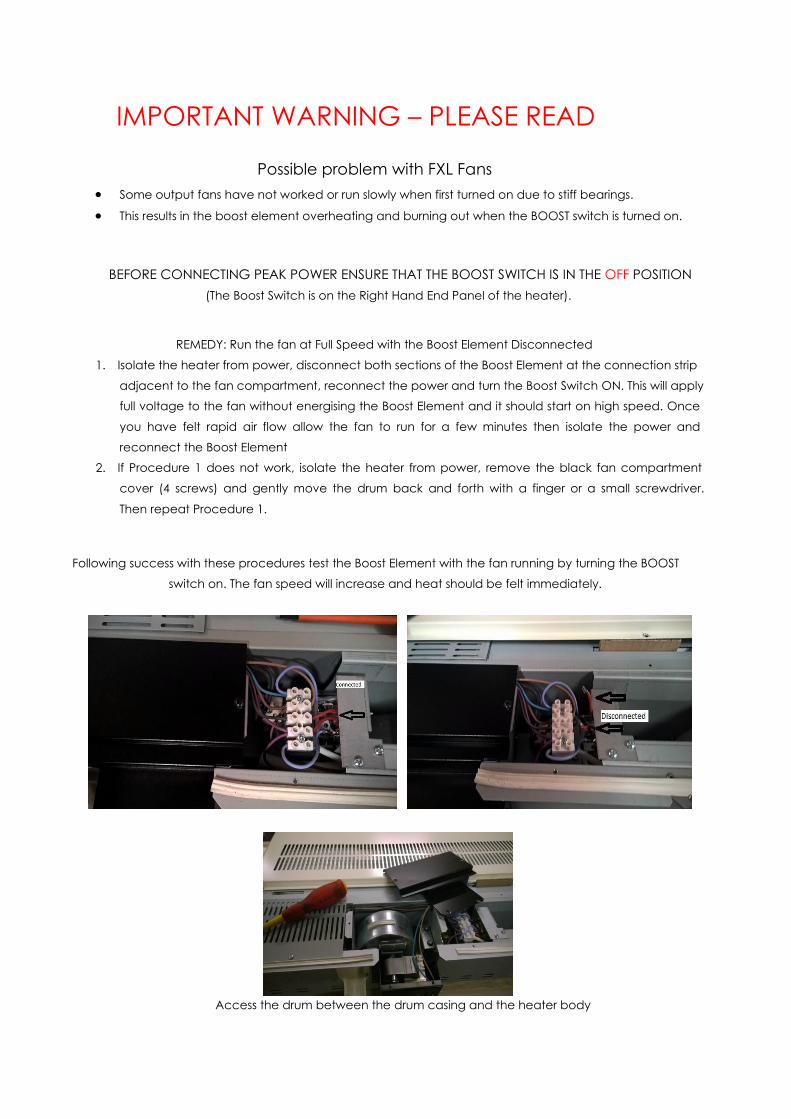
BEFORE CONNECTING PEAK POWER ENSURE THAT THE BOOST SWITCH IS IN THE OFF POSITION (The Boost Switch is on the Right Hand End Panel of the heater).
REMEDY: Run the fan at Full Speed with the Boost Element Disconnected
1. Isolate the heater from power, disconnect both sections of the Boost Element at the connection strip
adjacent to the fan compartment, reconnect the power and turn the Boost Switch ON. This will apply full voltage to the fan without energising the Boost Element and it should start on high speed. Once
you have felt rapid air flow allow the fan to run for a few minutes then isolate the power and
reconnect the Boost Element 2. If Procedure 1 does not work, isolate the heater from power, remove the black fan compartment
cover (4 screws) and gently move the drum back and forth with a finger or a small screwdriver.
Then repeat Procedure 1.
Following success with these procedures test the Boost Element with the fan running by turning the BOOST
switch on. The fan speed will increase and heat should be felt immediately.
Access the drum between the drum casing and the heater body
INSTALLATION INSTRUCTIONS
PREPARATION
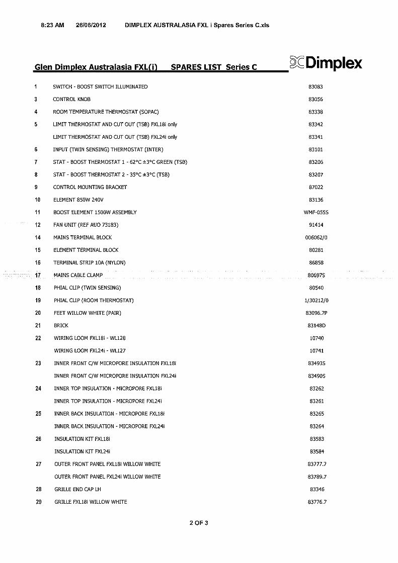
The heater will arrive separately from its storage bricks, the following bricks will be required.
FXL18i - 12 bricksFXL24i - 16 bricks
Two supplies are required for the operation of this heater - a restricted Off Peak or Economy 7 supply for the storage circuit, and an unrestricted supply for the fan boost element circuit.Thermostatic fan / boost control is provided on the heater, however the fan / boost operation may be customised by the introduction of an external timer to the heater (see section 3).
WARNING - This appliance must be earthed
Only heat resisting cable (min. rating V75) should be used. The wires in the mains cable will be coloured as follows:-
GREEN & YELLOW - EARTHBLUE - NEUTRAL
BROWN - LIVE
SUGGESTED FIXINGSSOLID BRICK/BLOCK - No. 10 Size plastic inserts, 8mm drill bit. Drill hole 15mm deeper than plastic insert length.PLASTERBOARD - If possible locate studding and use No. 10 woodscrews directly into the wood, otherwise M5 rawlplug intersets are suitable.NOTE: FOR OTHER WALL TYPES - (e.g. timberframe and hollow concrete) SEEK SPECIALIST ADVICE.
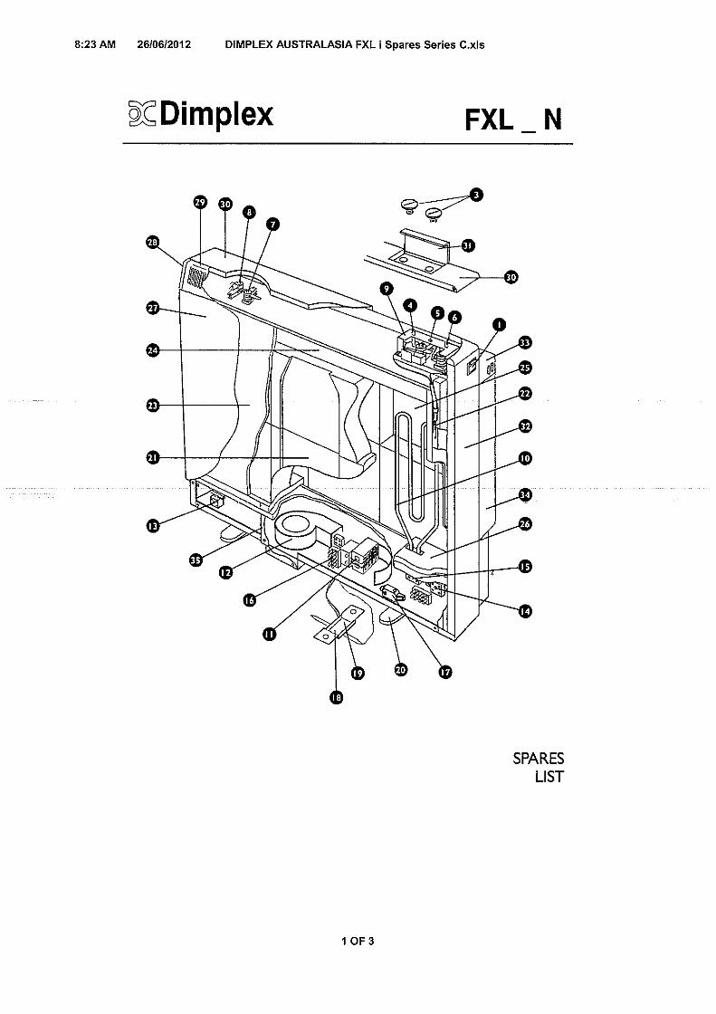
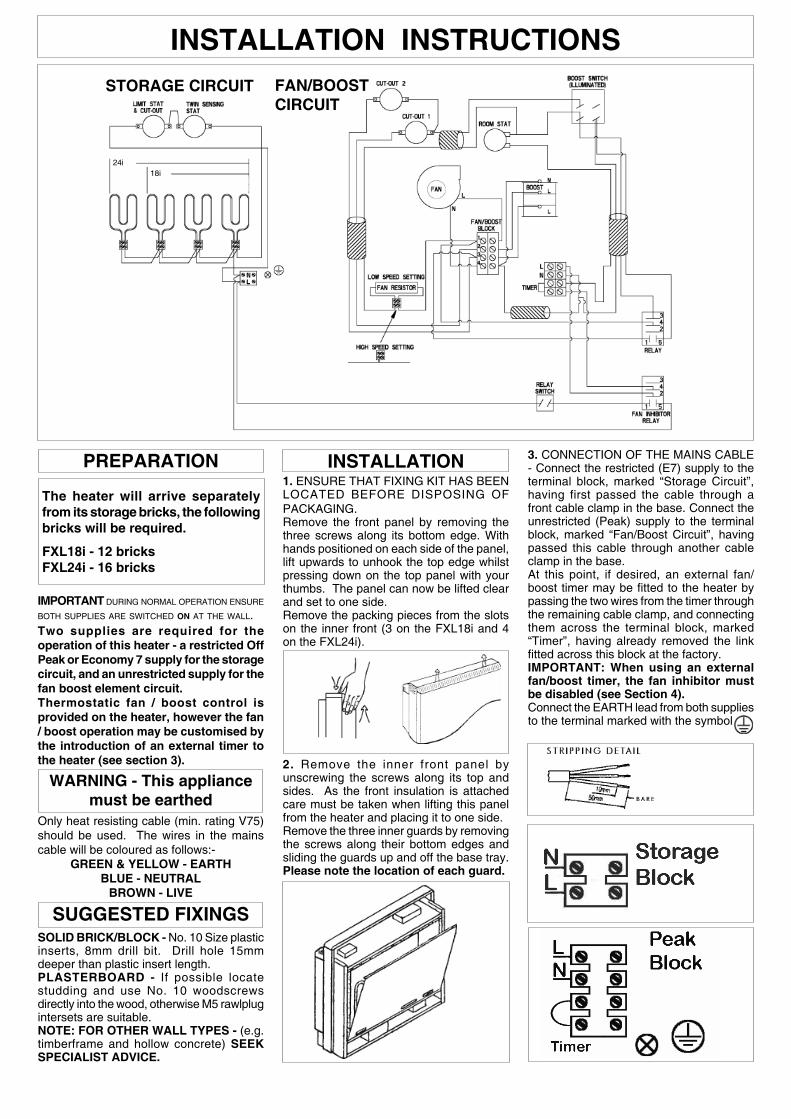
INSTALLATION1. ENSURE THAT FIXING KIT HAS BEEN LOCATED BEFORE DISPOSING OF PACKAGING.Remove the front panel by removing the three screws along its bottom edge. With hands positioned on each side of the panel, lift upwards to unhook the top edge whilst pressing down on the top panel with your thumbs. The panel can now be lifted clear and set to one side.Remove the packing pieces from the slots on the inner front (3 on the FXL18i and 4 on the FXL24i).
2. Remove the inner front panel by unscrewing the screws along its top and sides. As the front insulation is attached care must be taken when lifting this panel from the heater and placing it to one side.Remove the three inner guards by removing the screws along their bottom edges and sliding the guards up and off the base tray. Please note the location of each guard.
3. CONNECTION OF THE MAINS CABLE - Connect the restricted (E7) supply to the terminal block, marked “Storage Circuit”, having first passed the cable through a front cable clamp in the base. Connect the unrestricted (Peak) supply to the terminal block, marked “Fan/Boost Circuit”, having passed this cable through another cable clamp in the base.At this point, if desired, an external fan/boost timer may be fi tted to the heater by passing the two wires from the timer through the remaining cable clamp, and connecting them across the terminal block, marked “Timer”, having already removed the link fi tted across this block at the factory. IMPORTANT: When using an external fan/boost timer, the fan inhibitor must be disabled (see Section 4).Connect the EARTH lead from both supplies to the terminal marked with the symbol
IMPORTANT DURING NORMAL OPERATION ENSURE BOTH SUPPLIES ARE SWITCHED ON AT THE WALL.
STORAGE CIRCUIT FAN/BOOST CIRCUIT
24i18i
5. FAN SPEED SELECTION - At this point the installer must choose between Normal/High Fan or permanent High Fan option.Option 1 - The heater is factory set at Normal Fan. The fan will therefore:-(a) Run at NORMAL when the boost option
is not selected.(b) Run at NORMAL when the boost
is selected and the core is partially depleted.
(c) Automatically switch to HIGH when the boost is selected and the core is almost fully depleted.
Option 2 - If a High Fan is permanently required the installer must make the following adjustment.(a) Loosen the two screws securing the wires
to the resistor block.(b) Move the right wire to the left of the
block and tighten both wires in the left connection point of the resistor block effectively taking the resistor out of circuit. See Fan/Boost Circuit Diagram
6. Ensure that any slack is pulled back through each clamp and tighten the clamping screws. Secure cables to base of heater using ties provided in fi xing kit.
7. Place the heater on its feet, and in the desired position against the wall - DO NOT LIFT THE HEATER BY ITS TOP PANEL! Ensure that the heater is based on a fi rm level surface, at least 100mm from any end wall, and at least 100mm below any shelf or similar projection. Cut away the gripper rod or carpet which would prevent the heater sitting fi rmly on the fl oor.
8. Mark the position of the two outside corners of the wall bracket with the heater pushed tight against the wall. Remove the wall bracket from the heater by removing the screw at each end. Place the heater to one side and reposition the bracket against the wall using the corner marks for alignment.
9. THE FOLLOWING MUST BE APPLIED WHEN FIXING THE HEATER TO THE WALL BRACKET.
i) If no skirting board is present secure the heater through the wall bracket slots closest to the wall.
ii) If 100mm (4 in.) skirting is present secure the heater through the outer slots.
iii) If skirting taller that 150mm (6in.) is present this must be reduced to 150mm (6 in.) over the entire width of the heater plus 25mm (1 in.) at each end.
Do not fully tighten these screws until the bricks are loaded into the heater as some settling of the heater may occur.
NOTE: NEVER REMOVE THESE SCREWS WITHOUT FIRST UNLOADING THE HEATER.
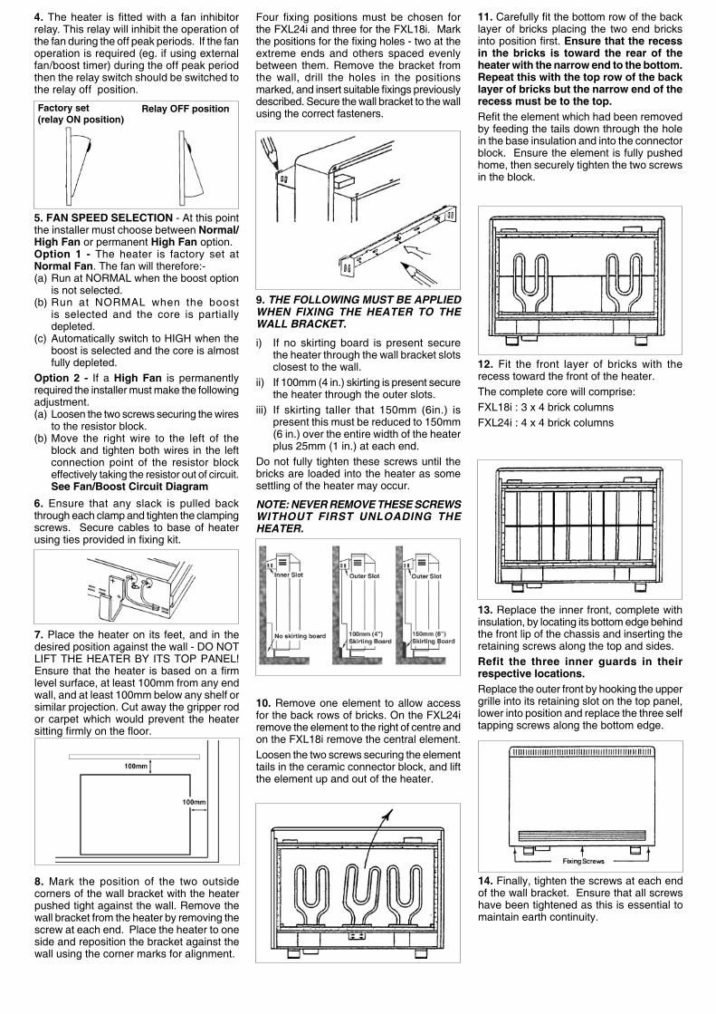
10. Remove one element to allow access for the back rows of bricks. On the FXL24i remove the element to the right of centre and on the FXL18i remove the central element.Loosen the two screws securing the element tails in the ceramic connector block, and lift the element up and out of the heater.
11. Carefully fi t the bottom row of the back layer of bricks placing the two end bricks into position fi rst. Ensure that the recess in the bricks is toward the rear of the heater with the narrow end to the bottom. Repeat this with the top row of the back layer of bricks but the narrow end of the recess must be to the top.Refi t the element which had been removed by feeding the tails down through the hole in the base insulation and into the connector block. Ensure the element is fully pushed home, then securely tighten the two screws in the block.
12. Fit the front layer of bricks with the recess toward the front of the heater.The complete core will comprise:FXL18i : 3 x 4 brick columnsFXL24i : 4 x 4 brick columns
13. Replace the inner front, complete with insulation, by locating its bottom edge behind the front lip of the chassis and inserting the retaining screws along the top and sides.Refit the three inner guards in their respective locations.Replace the outer front by hooking the upper grille into its retaining slot on the top panel, lower into position and replace the three self tapping screws along the bottom edge.
14. Finally, tighten the screws at each end of the wall bracket. Ensure that all screws have been tightened as this is essential to maintain earth continuity.
4. The heater is fi tted with a fan inhibitor relay. This relay will inhibit the operation of the fan during the off peak periods. If the fan operation is required (eg. if using external fan/boost timer) during the off peak period then the relay switch should be switched to the relay off position.
Factory set (relay ON position)
Relay OFF position
Four fi xing positions must be chosen for the FXL24i and three for the FXL18i. Mark the positions for the fi xing holes - two at the extreme ends and others spaced evenly between them. Remove the bracket from the wall, drill the holes in the positions marked, and insert suitable fi xings previously described. Secure the wall bracket to the wall using the correct fasteners.
OPERATING INSTRUCTIONS
Heat RetentionThis storage heater takes in energy when electricity tariffs are low, and retains it in the insulated core.
Automatic Input ControlAn automatic input control system varies the charge taken in response to weather conditions, taking into account the amount of energy already stored in the heater. It therefore provides an economic heating system requiring no adjustment by the user.
Core DischargeA thermostatically controlled fan draws air through the hot core, releasing the stored heat as and when required, providing a level of room temperature control superior to that of conventional storage heaters.
Boost HeatingA supplementary direct acting element provides additional boost heating when required. Although this may function outside reduced tariff periods, the boost will only operate when the more economical ‘stored energy’ is exhausted.
Setting the ControlsThe controls are located at the top right hand corner of the heater, both under the hinged fl ap, and on the side panel.
Safety Instructions1. Ventilate rooms well during commissioning.2. Do not move the heater in any way once
installed without the services of a competent electrician.
3. Do not cover the heater with clothing etc. at any time, or position furniture close to, or against, the heater.
4. Ensure clearances of at least 150mm between the heater and curtains.
ALSO REFER TO COVER PAGE
Due to the newness of materials, the heater will produce a slight smell for the fi rst few days of operation. In order to dispel these odours as quickly as possible:(i) During the day set the input room temperature control to MAXIMUM and the boost switch to OFF, allowing the fan to run as often as possible.(ii) During the night, ensure that the boost switch is set to OFF, and reduce the room temperature control setting to MINIMUM to enable the core to accept its full charge. Ensure both supplies are switched on at the wall.
Normal Use (after the fi rst 48 hours)
i) Keep both supplies switched on at the wall.ii) When only background heat is required (eg. when the room is unoccupied) set the temperature control to minimum.iii) When more heat is required in the room (eg. when the room is occupied) turn the temperature control to 5 or 6 to set the required room temperature.iv) At night time, set the temperature control back to MINIMUM, to allow the heater to accept its full charge.
Principles of Operation Control Functions
Output Controls ROOM TEMPERATURE CONTROL
The room temperature control will allow the fan to run until the desired room temperature has been achieved. Once this has been reached the fan will automatically cycle ON and OFF to maintain this temperature. If the room feels too warm the room temperature control should be adjusted anticlockwise; conversely if the room feels too cool it should be adjusted clockwise.
To maintain the appearance of the heater, wipe occasionally with a dry cloth when the heater is cool. Do not use abrasive powders or furniture polish.
Discolouration of wall fi nishes can sometimes occur immediately above a storage heater due to the properties of some paints and decorating materials or the presence of environmental impurities in the air (such as soot or incense generated from the burning of candles, etc). A suitable shelf may be fi tted to limit the extent of any wall discolouration.
10887 Issue 1
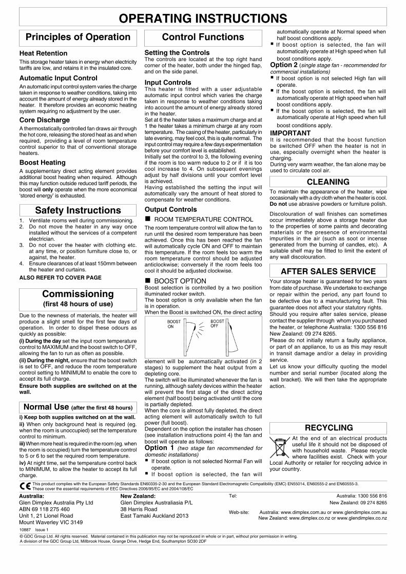
BOOST OPTIONBoost selection is controlled by a two position illuminated rocker switch. The boost option is only available when the fan is in operation.When the Boost is switched ON, the direct acting
element will be automatically activated (in 2 stages) to supplement the heat output from a depleting core. The switch will be illuminated whenever the fan is running, although safety devices within the heater will prevent the fi rst stage of the direct acting element (half boost) being activated until the core is partially depleted.When the core is almost fully depleted, the direct acting element will automatically switch to full power (full boost).Dependent on the option the installer has chosen (see installation instructions point 4) the fan and boost will operate as follows:Option 1 (two stage fan recommended for domestic installations) If boost option is not selected Normal Fan will operate. If boost option is selected, the fan will
Commissioning(fi rst 48 hours of use)
Input ControlsThis heater is fitted with a user adjustable automatic input control which varies the charge taken in response to weather conditions taking into account the amount of energy already stored in the heater.Set at 6 the heater takes a maximum charge and at 1 the heater takes a minimum charge at any room temperature. The casing of the heater, particularly in late evening, may feel cool, this is quite normal. The input control may require a few days experimentation before your comfort level is established.Initially set the control to 3, the following evening if the room is too warm reduce to 2 or if it is too cool increase to 4. On subsequent evenings adjust by half divisions until your comfort level is achieved.Having established the setting the input will automatically vary the amount of heat stored to compensate for weather conditions.
AFTER SALES SERVICE
automatically operate at Normal speed when half boost conditions apply. If boost option is selected, the fan will automatically operate at High speed when full boost conditions apply.
Option 2 (single stage fan - recommended for commercial installations) If boost option is not selected High fan will operate. If the boost option is selected, the fan will automatically operate at High speed when half boost conditions apply. If the boost option is selected, the fan will automatically operate at High speed when full
boost conditions apply.
IMPORTANTIt is recommended that the boost function be switched OFF when the heater is not in use, especially overnight when the heater is charging.During very warm weather, the fan alone may be used to circulate cool air.
At the end of an electrical products useful life it should not be disposed of with household waste. Please recycle where facilities exist. Check with your
Local Authority or retailer for recycling advice in your country.
RECYCLING
Your storage heater is guaranteed for two years from date of purchase. We undertake to exchange or repair within the period, any part found to be defective due to a manufacturing fault. This guarantee does not affect your statutory rights.Should you require after sales service, please contact the supplier through whom you purchased the heater, or telephone Australia: 1300 556 816New Zealand: 09 274 8265.Please do not initially return a faulty appliance, or part of an appliance, to us as this may result in transit damage and/or a delay in providing service.Let us know your diffi culty quoting the model number and serial number (located along the wall bracket). We will then take the appropriate action.
CLEANING
This product complies with the European Safety Standards EN60335-2-30 and the European Standard Electromagnetic Compatibility (EMC) EN55014, EN60555-2 and EN60555-3. These cover the essential requirements of EEC Directives 2006/95/EC and 2004/108/EC
© GDC Group Ltd. All rights reserved. Material contained in this publication may not be reproduced in whole or in part, without prior permission in writing. A division of the GDC Group Ltd, Millbrook House, Grange Drive, Hedge End, Southampton SO30 2DF
Australia:Glen Dimplex Australia Pty LtdABN 69 118 275 460Unit 1, 21 Lionel RoadMount Waverley VIC 3149
Tel: Australia: 1300 556 816 New Zealand: 09 274 8265
Web-site: Australia: www.dimplex.com.au or www.glendimplex.com.au New Zealand: www.dimplex.co.nz or www.glendimplex.co.nz
New Zealand:Glen Dimplex Australiasia P/L38 Harris RoadEast Tamaki Auckland 2013