derivative controlled magnetic amplifiers
TRANSCRIPT
Derivative Controlled Magnetic Amplifiers A. D . S G H N I T Z L E R
A S S O C I A T E M E M B E R
T ^ H E C I R C U I T s h o w n in F ig . 1 is of a low-level fast-A response m a g n e t i c ampl i f ie r , as d e v e l o p e d for such
low-level s ignals as a r e p r o v i d e d b y t h e r m o c o u p l e s , s t r a in gauges , e tc . Rect i f ie rs a r e n o t i n c l u d e d in t h e i n p u t c i rcui t , t hus e l i m i n a t i n g t h e res t r i c t ion w h i c h t h e y i m p o s e on t h e m i n i m u m signal vo l t age . L o w drift , fast r e sponse , a n d h i g h ga in a r e o b t a i n e d b y t h e use of a c o m b i n a t i o n of d e l a y e d posi t ive v o l t a g e - c u r r e n t a n d n e g a t i v e c u r r e n t -vo l tage feedback . T h e d e l a y e d n e g a t i v e f eedback c u r r e n t -vol tage f rom a resistive l oad is a d d e d t o t h e s ignal vo l t age in t h e con t ro l c i rcu i t of t h e first s t age so t h a t it ampl i f ies t h e a v e r a g e i n c r e m e n t s of s ignal vo l t age p e r ha l f cycle of p o w e r s u p p l y vo l t age . T h e posi t ive v o l t a g e - c u r r e n t feedback is ad jus ted to j u s t c o m p e n s a t e for rectif ier l e a k a g e a n d e d d y c u r r e n t losses in t h e second s tage . T h e funct ion of t h e second s tage is to ampl i fy a n d s u m t h e o u t p u t vo l t age of t h e first s tage .
I n a 2-stage ampl i f ier , drift is a l m o s t en t i r e ly d u e t o var ia t ions in p a r a m e t e r s of t h e first s tage . T h e first s t age funct ions as a de r iva t ive ampl i f ie r a n d t h e second s t age as a n in t eg ra to r . S ince t h e i n p u t s tage o p e r a t e s u p o n t h e a v e r a g e i n c r e m e n t of s ignal vo l t age p e r ha l f cycle r a t h e r t h a n t h e a v e r a g e s ignal vo l t age p e r ha l f cycle , t h e effect of va r i a t ions in t h e b a c k res i s tance of t h e rectifiers a n d of core m a g n e t i z i n g c u r r e n t u p o n t h e o u t p u t is d i m i n i s h e d b y t h e r a t i o of t h e i n c r e m e n t t o t h e e n t i r e s ignal vo l t age .
Re fe r r ing to F ig . 1, cores I a n d I I a r e p a r t s of ha l f -wave
POSITIVE DERIVATIVE AMPLIFIER GIO
CORE I Λ LOW PASS FILTER
13ion X 4
NEGATIVE DERIVATIVE AMPLIFIER
Fig. 1. Complete amplif ier incorporat ing ha l f -wave der ivat ive amplifier
amplif iers c o n n e c t e d in p u s h - p u l l . Ii a n d 12 a r e c u r r e n t sources w h i c h b ias t h e 2 ampl i f iers t o z e r o o u t p u t w h e n t h e i n p u t is ze ro . Ef is t h e s ignal vo l t age a n d Ef is a nega t ive feedback vo l t age p r o p o r t i o n a l to t h e load c u r r e n t . T h e b a r over t h e vo l t age s y m b o l i nd i ca t e s t h e a v e r a g e vo l tage over a hal f cycle . W i t h a resistive load , E^ is d e l a y e d 1 cycle b y t h e ampl i f ie r . W h e n cond i t i ons a r e such t h a t jS^has b e e n c o n s t a n t for 1 cycle or m o r e , £ ^ = £ < a n d t h e i n p u t to t h e ha l f -wave ampl i f iers cores I a n d I I is
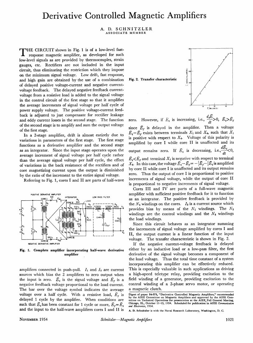
Fig. 2. Trans fer characterist ic
1 30 f, (JKiLiiyoiTS)
ze ro . H o w e v e r , if £ ^ is inc reas ing , i .e., Ei>Ef
s ince Ef is d e l a y e d in t h e ampl i f ie r . T h e n a vo l t age Ei—Ef exists b e t w e e n t e r m i n a l s Χχ a n d X 4 , s u c h t h a t Χχ is pos i t ive w i t h r e s p e c t t o X4. V o l t a g e of th is p o l a r i t y is ampl i f i ed b y c o r e I w h i l e c o r e I I is unaf fec ted a n d its
dE o u t p u t r e m a i n s ze ro . I f E^ is dec rea s ing , i .e., dt
' < 0 ,
Ei<Ef a n d t e r m i n a l Xi is n e g a t i v e w i t h r e spec t t o t e r m i n a l X4. I n this case , t h e vo l t age Ei—Ef= — \Ef—15< is ampl i f ied b y c o r e I I w h i l e c o r e I is unaf fec ted a n d its o u t p u t r e m a i n s ze ro . T h u s t h e o u t p u t of co re I is p r o p o r t i o n a l to posi t ive i n c r e m e n t s of s ignal v o l t a g e , w h i l e t h e o u t p u t of co re I I is p r o p o r t i o n a l t o n e g a t i v e i n c r e m e n t s of s ignal vo l t age .
C o r e s I I I a n d I V a r e p a r t s of a ful l -wave m a g n e t i c ampl i f i e r w i t h sufficient pos i t ive f eedback for i t t o funct ion as a n i n t e g r a t o r . T h e pos i t ive f eedback is p r o v i d e d b y t h e A'4 w i n d i n g s on t h e cores , h is a c u r r e n t source w h i c h p r o v i d e s b i a s b y m e a n s of t h e Ni w i n d i n g s . T h e N2 w i n d i n g s a r e t h e c o n t r o l w i n d i n g s a n d t h e w i n d i n g s t h e l oad w i n d i n g s .
S ince th is c i r cu i t b e h a v e s as a n i n t e g r a t o r s u m m i n g t h e i n c r e m e n t s of s ignal v o l t a g e ampl i f i ed b y cores I a n d I I , t h e o u t p u t c u r r e n t is a l i n e a r func t ion of t h e i n p u t vo l t age . T h e t ransfer c h a r a c t e r i s t i c is s h o w n in F ig . 2.
If t h e n e g a t i v e c u r r e n t - v o l t a g e f eedback is d e l a y e d e i t he r b y a n i n d u c t i v e l o a d o r a low-pass filter, t h e first d e r i v a t i v e of t h e s igna l v o l t a g e b e c o m e s a c o m p o n e n t of t h e l o a d vo l t age . T h u s t h e t o t a l t i m e c o n s t a n t of a sys tem i n c o r p o r a t i n g th is ampl i f ie r c a n b e effectively r e d u c e d . T h i s is espec ia l ly v a l u a b l e in s u c h a p p l i c a t i o n s as d r i v i n g a h i g h - s p e e d t e l e t y p e r e l ay , p r o v i d i n g exc i t a t i on to t h e field w i n d i n g of a g e n e r a t o r , p r o v i d i n g exc i t a t i on to t h e c o n t r o l w i n d i n g of a 2 - p h a s e se rvo m o t o r , o r o p e r a t i n g a m a g n e t i c c l u t c h . Digest of paper 54-375, "Derivative Controlled Magnetic Amplifiers," recommended by the AIEE Committee on Magnetic Amplifiers and approved by the AIEE Committee on Technical Operations for presentation at the AIEE, Fall General Meeting, Chicago, 111., October 11-15, 1954. Scheduled for publication in AIEE Communication and Electronics, 1954.
A. D. Schnitzler is with the Naval Research Laboratory, Washington, D. C.
N O V E M B E R 1954 Schnitzler—Magnetic Amplifiers 1021