described in previous publications by bovie,' waite, derby, be used
TRANSCRIPT
A PORTABLE ADAPTOMETER*
GEORGE S. DERBY, M.D.Boston
AND(By invitation)
PAUL A. CHANDLER, M.D.Boston
AND
LOUISE L. SLOAN, PH.D.Boston
INTRODUCTIONAn apparatus for testing both the light minimum and the
light difference in dark adaptation, and the use of thisapparatus in the early diagnosis of glaucoma, has beendescribed in previous publications by Bovie,' Waite, Derby,and Kirk,8 Derby, Waite, and Kirk,3 and Derby, Chandler,and O'Brien.2 In the last of this series of papers it wasshown that a test of the light minimum is of greater valuein the diagnosis of glaucoma than is a test of the light differ-ence. Since, therefore, only the light minimum need betested, it becomes possible to devise an instrument simplerin construction than the one previously described, which maybe used in the ordinary dark-room of a doctor's office.The essential and desirable characteristics of an instru-
ment by means of which accurate determinations of the lightthreshold may be made during the course of dark adaptationmay be summarized as follows:
(1) Standardization of Scale.-In order that determina-tions made at widely separated intervals of time may be
* From the Ophthalmological Department, Haivard Medical School, andthe Massachusetts Eye and Ear Infirmary.
110
A Portable Adaptometer
accurately compared the instrument must be so standardizedthat the same scale reading corresponds at all times to thesame brightness of the test spot. The brightness should,moreover, be expressed in absolute'units if the results ob-tained with different types of adaptometers are to be com-pared.
(2) Range of Brightness.-In previous experiments,83 inwhich the course of dark adaptation was determined fornormal observers, cases of early glaucoma, and cases of estab-lished glaucoma with and without operation, it was foundessential that the apparatus used be capable of furnishing awide range of variation in the brightness of the test spot.Several factors are responsible for this. The magnitude ofthe light threshold for a given individual at the beginning ofdark adaptation is frequently as much as 100 times its valueafter thirty minutes or more of dark adaptation. The varia-tion, moreover, in the light thresholds of different observersis considerable, even for normal eyes. When, however, thegroup of observers to be tested includes not only normalobservers, but also pathologic cases in whom the diseaseconditions are in various stages of advancement or recession,the variation is still greater. A patient with establishedglaucoma may, for example, require 100 times as much lightfor a thieshold sensation as is required by a normal observerafter the same interval of dark adaptation. Difference in thesize of the pupil is a third cause of variation in the value ofthe light threshold, which becomes of especial importance ifthe procedure recommended by us of immobilizing the pupilwith pilocarpin is followed. It has been pointed out inprevious articles that, in'order tQ use the value of the lightthreshold in diagnosis, either the influence on the results ofthe size of the patient's pupil must be'controlled or else acorrection must be applied in making the computations.Our procedure consists in immobilizing the pupil, measuringits diameter, and applying a correction factor to the results
-111
DERBY, CHANDLER, AND SLOAN:
in order to eliminate the effect of this variable. Since thearea of the pupil after it has been fixed with pilocarpin maybe as small as 1 sq. mm., whereas, after an iridectomy, it mayeasily be as great as 50 sq. mm., there may result from thiscause alone a fifty-fold variation in the light threshold. Ourprevious experience has shown that, due to the various fac-tors outlined above, an instrument for measuring the changesin the light minimum during dark adaptation should becapable of a variation in intensity between the approximatelimits of 1 and 30,000 micromillilamberts.
(3) Ease of Operation.-It is desirable, although perhapsnot essential, that the brightness of the test spot be con-tinuously adjustable by a single regulating device. A meansof recording automatically each measurement of the lightthreshold is also of decided advantage in view of the factthat all the determinations must be carried out in the dark-room.
(4) Data on Normal Observers.-If the measurements ob-tained with the adaptometer are to be used in the detectionof pathologic conditions of the eye, we must obviously firsthave considerable information as to the results to be ex-pected from normal observers. It is not sufficient to havedata on the average dark adaptation curve for a group ofnormal observers. This represents merely the central ten-dency of the group, and gives no indication of the extent towhich a given normal individual may differ from the average.If, however, a statistical study is made of the results ob-tained by testing a sufficiently large group of normal ob-servers, it becomes possible to set a limit to the probableextent of normal variation. The results for any given indi-vidual which fall outside this boundry are to be regarded asindicative of possible pathologic changes. The greater thedeviation from normal, the more certain we may be of theexistence of a pathologic condition.
112
A Portable Adaptometer
OTHER ADAPTOMETERS USED IN CLINICAL MEASUREMENTSOF LIGHT SENSE
Before proceeding to a description of our own apparatuswe shall discuss briefly several forms of adaptometer whichhave been devised by others. We shall not attempt to givehere a complete account of all the devices which have beenused in testing the light threshold. A description of theinstruments devised by Nagel,6 by Piper,7 and by Ferree andRand4'5 should, however, be of interest for comparison withthe description of our apparatus.
In Nagel's adaptometer6 light from three incandescentlamps is transmitted through two milk-glass plates to athird, which serves as the test spot. The brightness of thelatter is regulated by varying the illuminated areas of theother two surfaces. An Aubert diaphragm placed directlybehind one of the milk glasses provides for the fine changesin brightness. The area of the diaphragm may be variedfrom 1 to 10,000 sq. mm. The gross changes in brightnessare produced by inserting screens containing a series of holesbehind the other milk-glass plate. Three screens are pro-vided, each of which reduces the effective area of the lumi-nous surface to 1/20. The three screens together provide fora reduction in brightness to 1/8000 of the original value. Theratio of the highest to the lowest brightness is, therefore,80,000,000: 1. Since the maximum brightness of the testspot is equivalent to an illumination of 1.45 meter candles,the absolute level and the range are such that the instrumentis suitable for all possible cases.An improved form of the Nagel adaptometer has been de-
vised by Piper,7 in which two Aubert diaphragms are sub-stituted for the single diaphragm used in conjunction withscreens containing fixed openings. As a result of this modi-fication it is possible to vary the brightness of the test spot ina continuous series from the highest to the lowest point byfirst decreasing one diaphragm to its smallest area, then
8
113
DERBY, CHANDLER, AND SLOAN:
decreasing the second in the same way. According to Piper,it is impractical to use apertures smaller in area than 16 sq.mm. because, when this point is reached, it is difficult tomake a sufficiently gradual change in brightness. Since thearea of each diaphragm when completely opened is 10,000sq. mm., the range of intensity provided is slightly less than400,000: 1. No provisions are made in either of these instru-ments for controlling the voltage at which the incandescentlamps are operated.
Ferree and Rand4,5 point out the difficulty of illuminatinguniformly a surface of the size needed in testing the lightthreshold. In their apparatus this difficulty is overcome byemploying a surface so small that the desired evenness inbrightness is easily obtained. A magnified image of this sur-face is then projected on a larger surface at a distance of6 meters by means of a suitable lens. The use of a projectionlens also solves the problem of providing a means of varyingthe brightness of the test spot without altering the evennessof distribution of the light or changing the size or shape ofthe image. The principle employed in accomplishing this iswell illustrated in the eye. The brightness of the retinalimage is regulated by means of the pupil without producingany change in the shape, size, or evenness of illumination ofthis image. For, since each point in the image receives lightfrom the entire lens, any reduction in the effective aperture ofthe lens produces an equal reduction in the amount of lightreaching each point in the image. The brightness of everypart of the image, is, therefore, proportional to the exposedarea of the lens. In Ferree and Rand's apparatus the reduc-tion in the effective area of the lens is accomplished by plac-ing a variable diaphragm as close as possible to the projec-tion lens. No data are given as to the range of intensityobtainable with this instrument. Fluctuations in light in-tensity due to changes in current are controlled by means ofan ammeter and a rheostat.
114
A Portable Adaptometer
In the instruments described above variable diaphragmshave been used in each case to change the brightness of thetest surface. In other forms of adaptometers changes in thedistance of the light source, Nicol prisms, and absorbingwedges are some of the methods used. The range which maybe conveniently obtained by varying the distance of thesource is limited. The intensity of light transmitted by apair of Nicol prisms varies as the square of the cosine of theangle between them. It is therefore zero when the prismsare at right angles, increases continuously as the anglebetween them is decreased, and reaches its maximum whenthe angle is zero. Consequently it is possible theoretically toobtain intensities ranging between any desired limits bychoosing a light source of the proper candle-power. In orderto obtain, for example, intensities ranging from 30,000 to1 ,uml. the source of light must be so chosen that the inten-sity of light transmitted by the Nicol prisms is 30,000 ,uml.when the angle between them is zero. Intensities of 3,000,300, 30, and 3 ,ml. correspond then respectively to anglesof 71, 84, 88, and 89.5 degrees approximately. It is obviousfrom these figures that a high degree of precision cannot beobtained in the variation of the intensity at the low end ofthe scale. This difficulty could be avoided by using auxiliarymeans of reducing the intensity in fixed steps. The con-venience of a single adjustment for varying the intensitywould, however, be lost.
In each of the two remaining methods, the use of a vari-able diaphragm and of absorbing wedges, certain advantagesand disadvantages may be pointed out. A diaphragm isprobably simpler and more likely to remain in proper adjust-ment than a wedge. The range of variation provided is,however, determined by the ratio of its largest to its smallestaperture. Unless, therefore, very large diaphragms are usedit must be possible to decrease the aperture to. an extremelysmall value in order to obtain an adequate range. In thiscase especial care must be taken that at low intensities a
115
DERBY, CHANDLER, AND SLOAN:
sufficiently fine adjustment is provided. Absorbing wedges,on the contrary, may easily be constructed of any desiredrange of transmission. Moreover, if the density of the wedgeis made proportional to the distance along its length, thenthe percentage change in brightness corresponding to a givenamount of movement of the wedges is the same at everypoint. For these reasons wedges have been used to vary theintensity in the instrument we are about to describe.
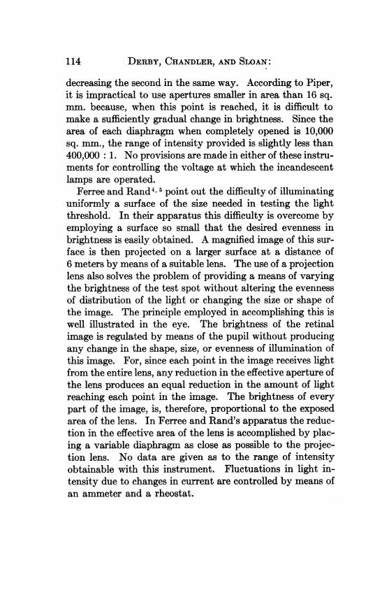
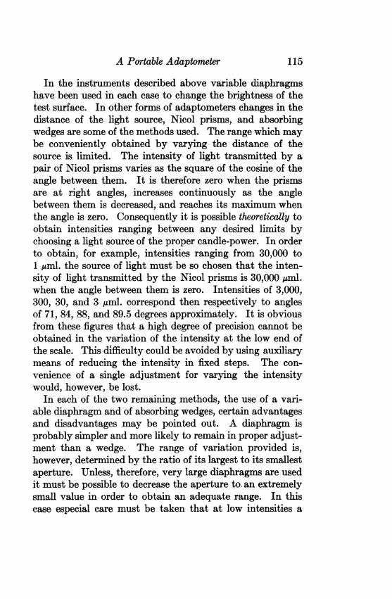
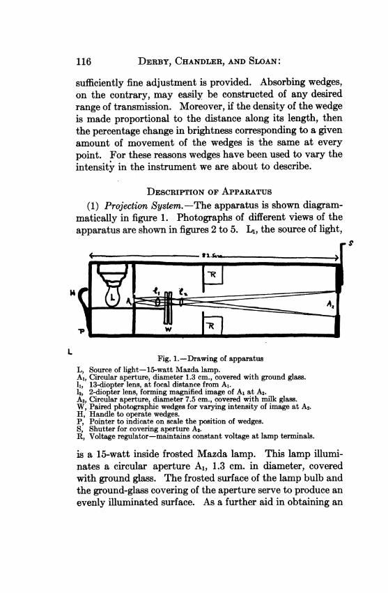
DESCRIPTION OF APPARATUS(1) Projection System.-The apparatus is shown diagram-
matically in figure 1. Photographs of different views of theapparatus are shown in figures 2 to 5. L1, the source of light,
Fig. 1.-Drawing of apparatusL, Source of light-15-watt Mazda lamp.Al, Circular aperture, diameter 1.3 cm., covered with ground glass.1, 13-diopter lens, at focal distance from Al.12, 2-diopter lens, forming magnified image of A1 at A2.A2, Circular aperture, diameter 7.5 cm., covered with milk glass.W, Paired photographic wedges for varying intensity of image at A2.H, Handle to operate wedges.P, Pointer to indicate on scale the position of wedges.S, Shutter for covering aperture A2.R, Voltage regulator-maintains constant voltage at lamp terminals.
is a 15-watt inside frosted Mazda lamp. This lamp illumi-nates a circular aperture A1, 1.3 cm. in diameter, coveredwith ground glass. The frosted surface of the lamp bulb andthe ground-glass covering of the aperture serve to produce anevenly illuminated surface. As a further aid in obtaining an
116
Fig. 2.-Side view of apparatus.
__d..
Fig. 3.-Side view of apparatus, showing lamp compartment and wedges.
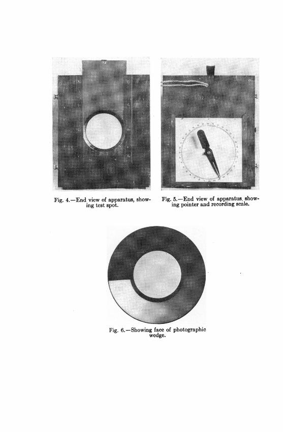
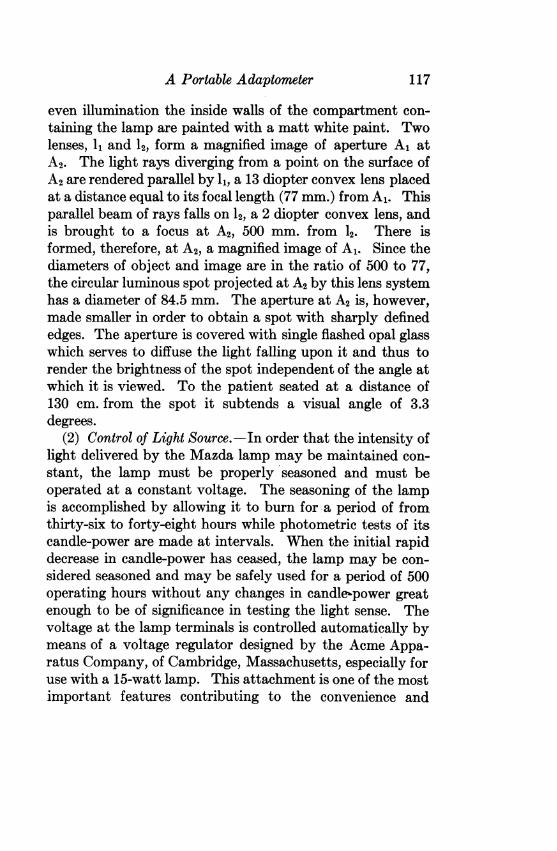
Fig. 4.-End view of apparatus, show- Fig. 5.-End view of apparatus, show-ing test spot. ing pointer and recording scale.
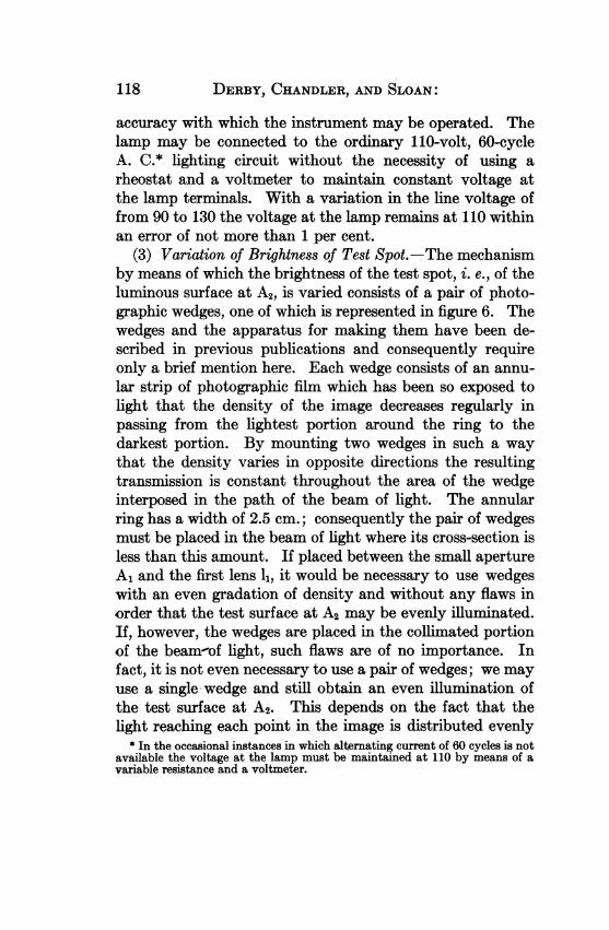
Fig. 6.-Showing face of photographicwedge.
A Portable Adaptometer
even illumination the inside walls of the compartment con-taining the lamp are painted with a matt white paint. Twolenses, I1 and 12, form a magnified image of aperture A1 atA2. The light rays diverging from a point on the surface ofA2 are rendered parallel by l, a 13 diopter convex lens placedat a distance equal to its focal length (77 mm.) from A1. Thisparallel beam of rays falls on 12, a 2 diopter convex lens, andis brought to a focus at A2, 500 mm. from 12. There isformed, therefore, at A2, a magnified image of A1. Since thediameters of object and image are in the ratio of 500 to 77,the circular luminous spot projected at A2 by this lens systemhas a diameter of 84.5 mm. The aperture at A2 is, however,made smaller in order to obtain a spot with sharply definededges. The aperture is covered with single flashed opal glasswhich serves to diffuse the light falling upon it and thus torender the brightness of the spot independent of the angle atwhich it is viewed. To the patient seated at a distance of130 cm. from the spot it subtends a visual angle of 3.3degrees.
(2) Control of Light Source.-In order that the intensity oflight delivered by the Mazda lamp may be maintained con-stant, the lamp must be properly seasoned and must beoperated at a constant voltage. The seasoning of the lampis accomplished by allowing it to burn for a period of fromthirty-six to forty-eight hours while photometric tests of itscandle-power are made at intervals. VVhen the initial rapiddecrease in candle-power has ceased, the lamp may be con-sidered seasoned and may be safely used for a period of 500operating hours without any changes in candle-power greatenough to be of significance in testing the light sense. Thevoltage at the lamp terminals is controlled automatically bymeans of a voltage regulator designed by the Acme Appa-ratus Company, of Cambridge, Massachusetts, especially foruse with a 15-watt lamp. This attachment is one of the mostimportant features contributing to the convenience and
117
DERBY, CHANDLER, AND SLOAN:
accuracy with which the instrument may be operated. Thelamp may be connected to the ordinary 110-volt, 60-cycleA. C.* lighting circuit without the necessity of using arheostat and a voltmeter to maintain constant voltage atthe lamp terminals. With a variation in the line voltage offrom 90 to 130 the voltage at the lamp remains at 110 withinan error of not more than 1 per cent.
(3) Variation of Brightness of Test Spot.-The mechanismby means of which the brightness of the test spot, i. e., of theluminous surface at A2, is varied consists of a pair of photo-graphic wedges, one of which is represented in figure 6. Thewedges and the apparatus for making them have been de-scribed in previous publications and consequently requireonly a brief mention here. Each wedge consists of an annu-lar strip of photographic film which has been so exposed tolight that the density of the image decreases regularly inpassing from the lightest portion around the ring to thedarkest portion. By mounting two wedges in such a waythat the density varies in opposite directions the resultingtransmission is constant throughout the area of the wedgeinterposed in the path of the beam of light. The annularring has a width of 2.5 cm.; consequently the pair of wedgesmust be placed in the beam of light where its cross-section isless than this amount. If placed between the small apertureA1 and the first lens 11, it would be necessary to use wedgeswith an even gradation of density and without any flaws inorder that the test surface at A2 may be evenly illuminated.If, however, the wedges are placed in the collimated portionof the beamr-of light, such flaws are of no importance. Infact, it is not even necessary to use a pair of wedges; we mayuse a single wedge and still obtain an even illumination ofthe test surface at A2. This depends on the fact that thelight reaching each point in the image is distributed evenly
* In the occasional instances in which alternating current of 60 cycles is notavailable the voltage at the lamp must be maintained at 110 by means of avariable resistance and a voltmeter.
118
A Portable Adaptometer
over the entire cross-section of the collimated beam of light.A similar method has already been used by Ferree and Randin obtaining an evenly illuminated image. Their apparatusand the principles involved have been explained earlier inthis paper. These authors use an adjustable diaphragm forvarying the intensity. We have preferred to use photo-graphic wedges because they provide an easy means of vary-ing the intensity continuously and gradually over a widerange. Since the logarithm of the transmission varies ap-proximately with distance along the wedge, the same amountof rotation of the pair of wedges produces everywhereapproximately the same percentage change in the intensityof light. A pair of wedges was used in constructing thisinstrument because, at the time, a single wedge was notavailable having a sufficient density range.The density of the pair of annular wedges in the region
through which the beam of light passes is varied by rotatingthe wedges in opposite directions about an axis passingthrough the center of the rings perpendicular to the plane ofthe wedges. The wedges are caused to rotate by means ofthe handle shown in figure 1 at H. A shaft is connected atone end to this handle and at the other end to the center ofthe nearer wedge, so that when the handle is rotated in aclockwise direction the wedge also rotates in this direction.The two wedges are connected by means of fine chains whichare wound around two drums and a series of pulleys in sucha way that the rotation of the first wedge in a clockwise direc-tion produces an equal rotation of the other in a counter-clockwise direction, and vice versa. The position of thewedges is indicated by means of a pointer and a scalegraduated in degrees. These are shown in figure 5. Sincethe determinations of the light threshold are to be made incomplete darkness, it is desirable that the operator be able torecord automatically the position of the wedges correspond-ing to each determination of the light threshold. This may
119
DERBY, CHANDLER, AND SLOAN:
be done by inserting a pencil in the radial slot in the pointer(fig. 5) and making a mark on the paper scale beneath. Theend of the pointer is covered with radium paint so that itmay be located easily in the dark. The time at which adetermination is made can be read from a clock having aluminous dial and recorded on the same scale. A fresh scaleis inserted for each patient tested and serves as a record ofthe results of the test.
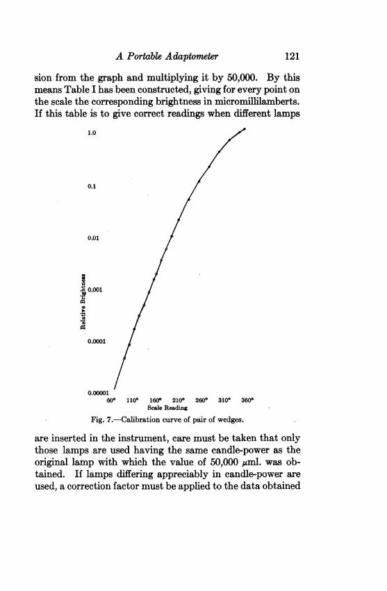
(4) Calibration of the Scale. The wedges were calibratedin position by making a series of readings of the brightnessof the test spot corresponding to a series of scale readings atclosely spaced intervals. A Macbeth illuminometer wasused to make these determinations. In order to obtain in-tensities high enough to be measured with a satisfactorydegree of precision a 100-watt lamp was substituted for the15-watt lamp while calibrating the wedges. In figure 7 isshown the calibration curve obtained. The brightness of thetest spot when the scale reading is 335 degrees, i. e., when thethinnest portion of the wedges is in the path of the beam oflight, is arbitrarily assigned a value of unity. The relativebrightness is plotted on a logarithmic scale on the ordinate,and the corresponding scale reading is plotted on the abscissa.The resulting graph approximates a straight line showingthat the logarithm of the transmission is approximately pro-portional to the number of degrees through which the pair ofwedges is rotated. In order to express the brightness of thetest spot in absolute units of intensity, a single determinationof its brightness at a given scale reading must be made withthe 15-watt lamp as the source of light, operated at thevoltage which has been selected as standard. Knowing thisvalue, any scale reading may be translated into absoluteunits of intensity. For example, if the brightness of the testspot with the scale at 335 degrees is 0.5 ml. or 50,000 ,uml., thebrightness corresponding to any other scale reading is ob-tained by reading off the proper value of relative transmis-
120
A Portable Adaptometer
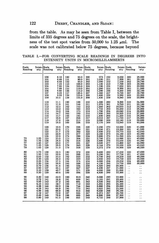
sion from the graph and multiplying it by 50,000. By thismeans Table I has been constructed, giving for every point onthe scale the corresponding brightness in micromillilamberts.If this table is to give correct readings when different lamps
1.0
0.1
0.01
-!0.001Ia
0.0001
0.00001600 1100 1600 2100 2600 3100 3600
Scale Reading
Fig. 7.-Calibration curve of pair of wedges.
are inserted in the instrument, care must be taken that onlythose lamps are used having the same candle-power as theoriginal lamp with which the value of 50,000 ,uml. was ob-tained. If lamps differing appreciably in candle-power areused, a correction factor must be applied to the data obtained
121
122 DERBY, CHANDLER, AND SLOAN:
from the table. As may be seen from Table I, between thelimits of 335 degrees and 75 degrees on the scale, the bright-ness of the test spot varies from 50,000 to 1.25 uml. Thescale was not calibrated below 75 degrees, because beyond
TABLE I.-FOR CONVERTING SCALE READINGS IN DEGREES INTOINTENSITY UNITS IN MICROMILLILAMBERTS
Scale Inten- Scale Inten- Scale Inten- Scale Inten- Scale Inten- Scale Inten-Reading sity Reading sity Reading sity Reading sity Reading sity Reading sity
100 6.10 150 85.0 200 975 250 6,950 300 28,500101 6.48 151 90.0 201 1,030 251 7,200 301 29,100102 6.85 152 95.0 202 1,080 252 7,450 302 29,700103 7.23 153 100.0 203 1,130 253 7,700 303 30,300104 7.60 154 105.0 204 1,190 254 7,950 304 30,900105 7.98 155 110.0 205 1,240 255 8,200 305 31,500106 8.60 156 115.2 206 1,290 256 8,460 306 32,100107 9.23 157 120.4 207 1,340 257 8,720 307 32,700108 9.85 158 125.6 208 1,400 258 8,980 308 33,300109 10.5 159 131.0 209 1,450 259 9,240 309 33,900
110 11.1 160 136 210 1,500 260 9,500 310 34,500111 11.8 161 146 211 1,570 261 9,780 311 35,100112 12.5 162 155 212 1,640 262 10,070 312 35,700113 13.3 163 165 213 1,710 263 10,350 313 36,300114 14.0 164 175 214 1,780 264 10,640 314 36,900115 14.7 165 185 215 1,850 265 10,920 315 37,500116 15.7 166 195 216 1,930 266 11,330 316 38,200117 16.6 167 205 217 2,010 267 11,730 317 38,900118 17.6 168 215 218 2,090 268 12,140 318 39,600119 18.5 169 226 219 2,170 269 12,540 319 40,300
120 19.5 170 236 220 2,250 270 12,950 320 41,000121 20.6 171 250 221 2,350 271 13,360 321 41,520122 21.7 172 263 222 2,450 272 13,770 322 42,040123 22.8 173 277 223 2,560 273 14,180 323 42,560124 23.9 174 290 224 2,660 274 14,590 324 43,080
75 1.25 125 25.0 175 304 225 2,760 275 15,000 325 43,60076 1.35 126 26.5 176 318 226 2,890 276 15,450 326 44,28077 1.45 127 28.0 177 331 227 3,020 277 15,900 327 44,96078 1.55 128 29.5 178 345 228 3,144 278 16,350 328 45,64079 1.65 129 31.0 179 358 229 3,272 279 16,800 329 46,320
80 1.75 130 32.5 180 372 230 3,400 280 17,250 330 47,00081 1.90 131 33.8 181 398 231 3,550 281 17,750 331 47,60082 2.05 132 35.0 182 323 232 3,700 282 18,250 332 48,20083 2.20 133 36.3 183 349 233 3,850 283 18,750 333 48,80084 2.35 134 37.5 184 374 234 4,000 284 19,250 334 49,40085 2.50 135 38.8 185 500 235 4,150 285 19,750 335 50,00086 2.70 136 41.4 186 524 236 4,320 286 20,40087 2.90 137 44.1 187 547 237 4,490 287 21,00088 3.10 138 46.7 188 571 238 4,660 288 21,60089 3.30 139 49.4 189 594 239 4,830 289 22,300
90 3.50 140 52.0 190 618 240 5,000 290 22,90091 3.72 141 54.6 191 649 241 5,165 291 23,40092 3.93 142 57.2 192 681 242 5,330 292 23,90093 4.15 143 59.7 193 712 243 5,495 293 24,500 ..94 4.36 144 62.3 194 744 244 5,660 294 25,000 ..95 4.58 145 64.9 195 775 245 5,825 295 25,500 ..96 4.88 146 68.9 196 815 246 6,050 296 26,100 ..97 5.19 147 72.9 197 855 247 6,275 297 26,700 ..98 5.49 148 76.9 198 895 248 6,500 298 27,300 ..99 5.80 149 81.0 199 935 249 6,725 299 27,900 ..
A Portable Adaptometer
this point on the scale the 100-watt lamp did not give in-tensities great enough to be measured with precision, andbecause from our previous investigations a range of from50,000 to 1.25 was known to be more than adequate for allpossible cases.
(5) General Considerations.-The instrument describedabove should prove feasible for use by the practising oph-thalmologist. It is small in size, 3212 by 912 by 712 inches,and weighs only 23 pounds. It is furnished with a handle bymeans of which it may be carried as easily as an ordinarysuitcase. A metal shutter is provided for the glass test sur-face in order that it may be protected from breakage whenthe instrument is carried about. The compartment con-taining the source of light is so constructed that no straylight escapes; consequently the apparatus does not need tobe enclosed in any way, but simply be placed on a table inthe dark-room at the proper distance in front of the patient.
PROCEDURE USED IN MAKING DETERMINATIONSThe procedure used by us in making a determination of the
course of dark adaptation has been described in a previousarticle.8 It may be of value, however, to consider here pos-sible simplifications which may be made in using the instru-ment not for research purposes, but for routine diagnosis.The advantages and disadvantages of making these sim-plifications will be pointed out. At the end of this discussiona routine procedure of the simplest possible sort will be brieflyoutlined.
(1) Pupil Fixation.-Our method of correcting for thevariable effect of the results of different sizes of pupil con-sists in immobilizing the pupil with pilocarpin, measuring itsdiameter, and applying to the results of the determination ofthe light threshold a correction factor based on the area ofthe pupil. The pupillary diameter is measured by means ofthe Zeiss slit-lamp and corneal microscope. The pupil,
123
DERBY, CHANDLER, AND SLOAN:
illuminated by the intense beam of light of the slit-lamp, isviewed under a magnification of 13, and its diameter meas-ured by means of the scale in the ocular micrometer. Al-though the involuntary eye movements of the patient, mag-nified, of course, in the same ratio, are a source of error andthe scale divisions are seen with difficulty because the scaleitself is not well illuminated, nevertheless determinations ofthe pupil diameter may in most cases be made to within onescale division. For a pupillary diameter of approximately1.5 mm., an error of measurement of one scale division corre-sponds to an error of 11 per cent. in the area. Since thepupils fixed with pilocarpin in this way are very rarelysmaller than this, we may say that the error of measurementis in general not greater than 11 per cent. If a slit-lamp isnot available, the measurement may be made by means ofany of the various types of pupillometers. With a Wesseleykeratometer it is possible to measure the pupillary diameterto within 0.25 mm., and thus to compute the proper correc-tion factor with an error not greater than about 33 per cent.for pupil sizes of 1.5 mm. or more. The measurement of thepupillary diameter may be made both before and after thethreshold determinations in order to be sure that there hasbeen no appreciable change in the size of the pupil during thecourse of the test. Our experience has shown, however, thatif the pupil does not react to light after thirty minutes haveelapsed following the instillation of three drops of a 1 percent. solution of pilocarpin, then determinations of itsdiameter made before and after the tests in the dark-roomagree within the error of the measurements.
(2) Pre-exposure.-The course of dark adaptation willobviously be influenced by the level of illumination to whichthe eye has been exposed immediately before the adaptationto darkness begins. In order to eliminate the variability inthe results due to this factor the following procedure wasadopted: The observer is seated facing a white screen 27
124

A Portable Adaptometer
inches distant, filling practically the entire field of view.The screen is illuminated to a brightness of approximately21 ml. (19.5 apparent foot-candles) by means of two 100-watt Mazda lamps mounted on adjustable floor stands andplaced out of the patient's line of vision at a distance ofapproximately four feet from the screen. The patient isallowed to look at this screen for a period of ten minutes ormore in order that a constant level of light adaptation may bereached. At the end of ten minutes the lights are turned out;the exact time at which this is done is recorded in order todetermine accurately the instant at which the process of darkadaptation commences. The screen having beenremoved fromits position in front of the patient, the test spot is exposedand the determinations of the light threshold may be made atthe desired intervals during the course of dark adaptation.Although the amount of light reaching the patient's retina
from this screen will vary with the size of the pupil, we havefound that the course of dark adaptation is affected by thisonly in the early stages, and by an amount which may beconsidered negligible. Slight variations in the brightness ofthe pre-exposure screen may also be considered of minor im-portance, although a decrease in brightness below the stan-dard level produces a greater effect on the results than anequal increase. If, therefore, it is not possible to obtain anillumination of the pre-exposure screen approximately equalto the chosen standard, it is better to use a higher brightnessthan a lower. If no other means are available, it may bepossible to obtain a pre-exposure screen of the proper bright-ness by substituting a plain white card for the acuity chartand using the source of light ordinarily employed in illumi-nating this chart. When possible, the pre-exposure screenshould be set up in the dark-room in which the determina-tions of the light minimum are to be made. In this way onlycan the pre-exposure immediately preceding the beginning ofdark adaptation be controlled.
125
DERBY, CHANDLER, AND SLOAN:
(3) Threshold Determinations. -Although an exact controlof fixation is probably not necessary, nor is it feasible forclinic patients, nevertheless the procedure followed in meas-uring the light minimum should be such as to insure that fora given patient approximately the same part of the retina betested at each determination. If a series of short exposuresof the test spot at different intensities are made and thepatient is asked to indicate whether or not he sees it, he islikely to be looking in quite a different direction each time,and as a result see the spot occasionally with the moresensitive periphery and occasionally with other less sensitiveparts of the retina. In order to prevent too much variabilityin result due to varying fixation conditions, the followingprocedure should be used in making each determination ofthe light threshold: The approximate threshold is first foundby darkening the spot rapidly until it disappears; then, whilethe patient continues to look in the direction in which it waslast seen, increasing its brightness rapidly until it appearsagain. This procedure is repeated a second time with a moregradual variation in the brightness of the spot, and the in-tensity at which the spot is first seen when it is increasedgradually in brightness is recorded as the threshold. In-vestigations as yet unfinished suggest that in fixating a dimobject when the eye is partially or completely dark-adapted,the tendency is not to turn the eye so that the image falls onthe fovea, but rather to take a slightly eccentric fixation, sothat the image falls on some other more sensitive part of theretina, which we- may call the scotopic fovea. Whether ornot this tentative conclusion will be confirmed by more ex-tended investigation we cannot say. Actual experience hasshown, however, that whatever may be the explanation, theprocedure outlined above for determining the threshold givesmore consistent and reproducible results than are obtainedwhen a series of short exposures of the test spot at differentbrightnesses are given.
126
A Portable Adaptometer
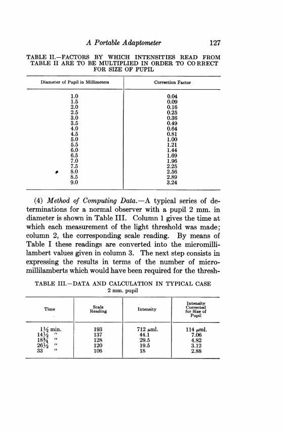
TABLE II.-FACTORS BY WHICH INTENSITIES READ FROMTABLE II ARE TO BE MULTIPLIED IN ORDER TO CORRECT
FOR SIZE OF PUPIL
Diameter of Pupil in Millimeters
1.01.52.02.53.03.54.04.55.05.56.06.57.07.5
0 8.08.59.0
Correction Factor
0.040.090.160.250.360.490.640.811.001.211.441.691.962.252.562.893.24
(4) Method of Computing Data. -A typical series of de-terminations for a normal observer with a pupil 2 mm. indiameter is shown in Table III. Column 1 gives the time atwhich each measurement of the light threshold was made;column 2, the corresponding scale reading. By means ofTable I these readings are converted into the micromilli-lambert values given in column 3. The next step consists inexpressing the results in terms of the number of micro-millilamberts which would have been required for the thresh-
TABLE III.-DATA AND CALCULATION IN TYPICAL CASE2 mm. pupil
IntensityTime Scale ItniyCorrectedReading Intensity for Size of
Pupil
1Y2 min. 193 712,uml. 114,uml.14½ " 137 44.1 7.0618% " 128 29.5 4.82262 " 120 19.5 3.1233 " 106 18 2.88
127
DERBY, CHANDLER, AND SLOAN:
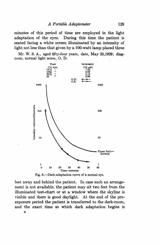
old had the patient's pupillary diameter been 5 mm. insteadof 2 mm., the former having been chosen arbitrarily as thestandard value. These, the final data given in column 4, areobtained from column 3 by multiplying each number incolumn 3 by 0.16, the correction factor for a 2 mm. pupil.Table II gives the correction factors for each diameter ofpupil. The final data are shown graphically in figure 8, inwhich time is plotted along the abscissa and the correspond-ing brightness is plotted according to a logarithmic scalealong the ordinate.
(5) Evaluation of Data.-The graph shown in figure 8 con-tains also a curve representing the upper limit of normalvariation. This curve and the details of its determinationhave been discussed in a previous paper.2 The necessary datawere obtained by testing a number of normal subjects withthe older and more elaborate form of apparatus previouslydescribed. It is probable that the curves for a given in-dividual tested by both machines would not differ greatlyfrom one another. Since, however, the color quality of thelight sources and the shapes of the test spot are different, aninvestigation must be made of this question. If there isfound to be any consistent difference of an appreciableamount in the data obtained with the two instruments, it willbe necessary to make a similar determination of the limits ofnormal variation, using the present apparatus. A compari-son of the results obtained with the two machines is now inprogress.
(6) Brief Summary of Essential Steps in Simplified Pro-cedure.-The following statement summarizes what we be-lieve to be the simplest possible procedure which can safelybe used in making a test of the course of dark adaptation,without neglecting considerations essential to the value ofthe test in diagnosis.Three drops of 1 per cent. pilocarpin are instilled at three-
minute intervals. Fixation of the pupils may be consideredto be complete at the end of thirty minutes. The last ten
128
A Portable Adaptometer 129
minutes of this period of time are employed in the lightadaptation of the eyes. During this time the patient isseated facing a white screen illuminated by an intensity oflight not less than that given by a 100-watt lamp placed threeMr. W. S. A., aged fifty-four years, date, May 23,1929; diag-
nosis, normal light sense, 0. D.TIME INTENSITY
1yM min. 114 jAml.14Y " 7.0618N " 4.8226Y2 3.1233 " 2.88
O.D.OS. Y -
1()00
100S
01.
4410
1
1000
100
10
Upper limit-normals
10 10 20 30 40 50 60
Time-minutes.
Fig. 8.-Dark-adaptation curve of a normal eye.
feet away and behind the patient. In case such an arrange-ment is not available, the patient may sit two feet from theilluminated test-chart or at a window where the skyline isvisible and there is good daylight. At the end of the pre-exposure period the patient is transferred to the dark-room,and the exact time at which dark adaptation begins is
9
DERBY, CHANDLER, AND SLOAN
recorded. The patient is seated facing the apparatus at adistance of 1.33 meters from the test spot. As soon as pos-sible determinations of the light threshold are made, first onone eye and then on the other, according to the directionspreviously given. When one eye is being tested, the other iskept covered by the patient's hand. In order to avoid con-fusion, the readings for the two eyes may be recorded withdifferently colored pencils. Three subsequent readings aremade at ten-minute intervals, requiring the patient to remainin the dark-room a little over thirty minutes. The operatorneed not stay in the dark-room except when readings arebeing taken, but must take care that the patient's eyes areclosed and covered with the hands when he is entering orleaving the room. At the end of the test the diameters of thepupils are measured. The results are then calculated accord-ing to the directions given above, and the final data plottedon a chart on which the normal curve is represented.
SUMMARYThe essential features of an instrument to be used in
measuring the changes in the light threshold during darkadaptation are outlined. The qualifications of several of themore important adaptometers already in use are consideredin relation to these requirements. A simple instrument isdescribed which fulfils these requirements and is suitable foruse in a doctor's office. The procedure to be followed inmaking a determination of the course of dark adaptation isoutlined.
REFERENCES1. Bovie, W. I.: Annual Report of Conservation Bureau, City of Boston, City
Document 9A, 1924, p. 15.2. Derby, G. S., Chandler, P. A., and O'Brien, M. E.: Tr. Sect. Ophth.,
A. M. A., 1928, p. 37.3. Derby, G. S., Waite, J. H., and Kirk, E. B.: Tr. Am. Ophth. Soc., 1926,
xxiv, p. 92.4. Ferree, C. E., and Rand, G.: Am. J. Ophth., 1920, iii, p. 1.5. Ferree, C. E., and Rand, G.: Arch. Ophth., 1926, lv, p. 245.6. Nagel, W. A.: Ztschr. f. Augenh., 1907, xvii, p. 201.7. Piper, H.: Klin. Monatsbl. f. Augenh., 1907 xlv, p. 357.8. Waite, J. H., Derby, G. S., and Kirk, E. B.: Tr. Ophth. Soc. U. Kingdom,
1925, xlv, p. 301.
130