description of the basic algorithm blocks and structures ... · description of the basic algorithm...
TRANSCRIPT
Description of the Basic Algorithm Blocks and Structures Representation in Courses of Algorithm Development
OLDŘICH HORÁK
Institute of System Engineering and Informatics, Faculty of Economics and Administration
University of Pardubice Studentská 84, 532 10 Pardubice
CZECH REPUBLIC [email protected]
LIBOR MITROVIČ
Department of Informatics, Faculty of Education
University of Hradec Králové Rokitanského 62, 500 03 Hradec Králové
CZECH REPUBLIC [email protected]
Abstract: - This paper describes the possible ways to explain and represent basic blocks and more complicated structures of algorithm in courses of algorithm development. The introduction includes a brief concept of basic structures used in the flowchart for the expression of several parts of the algorithms. Next parts are dedicated to the problematic structures description, and design possibilities in the LEGO® MINDSTORMS® and Scratch environments. Last part concludes the information above and introduces possible ways for the future work. Key-Words: - algorithm development, algorithm representation, algorithm expressing, flowchart, teaching of algorithms, basics of programming, LEGO MINDSTORMS, Scratch
1 Introduction There are many things in the world, which people want to express. If the things are static, the expression is simple. But, most of those change their state in the time. Some rules or patterns can make the changes and people want to express them in the well-arranged and understandable form.
The ability to represent the processes and actions in such form and the ability to understand them is the aim of the education in algorithms and algorithm development. Until recently, the education in this branch was the task of high schools. Nowadays, some courses of algorithm development are stable parts of education in technically focused secondary schools [9, 10]. Sometimes, the algorithms are included in the mathematics or other suitable courses or subject of education at elementary schools. An expedient form of expression needs to be used in this case. Conceptual thinking of the children and adolescents is not sufficiently developed for the abstract modeling in their age [8, 9]. The expression of the processes and their progress in the form of schemes and figures can be hardly understandable for the beginners. An abundance of particular shapes can be confusing.
The appropriate number of common shapes and figures can lead to simplification of the learning process. There is none strictly defined standard of the shapes used to express the algorithms via flowchart, but the common blocks for process and decision are used in general as well as some other
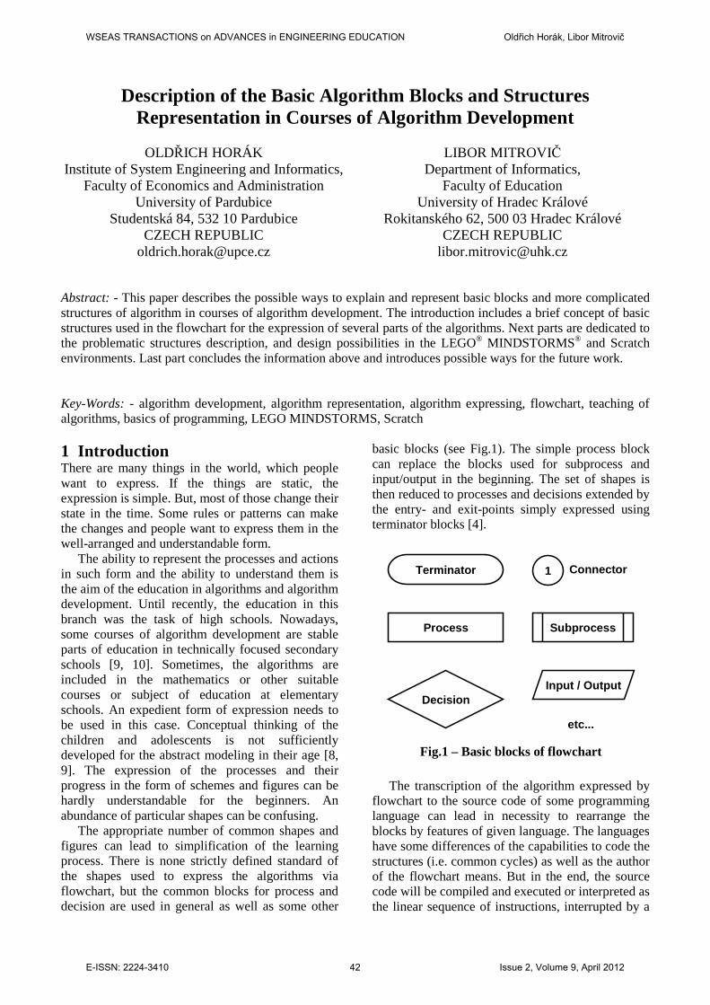
basic blocks (see Fig.1). The simple process block can replace the blocks used for subprocess and input/output in the beginning. The set of shapes is then reduced to processes and decisions extended by the entry- and exit-points simply expressed using terminator blocks [4].
Process
Decision
Terminator 1
Input / Output
Connector
Subprocess
etc...
Fig.1 – Basic blocks of flowchart The transcription of the algorithm expressed by
flowchart to the source code of some programming language can lead in necessity to rearrange the blocks by features of given language. The languages have some differences of the capabilities to code the structures (i.e. common cycles) as well as the author of the flowchart means. But in the end, the source code will be compiled and executed or interpreted as the linear sequence of instructions, interrupted by a
WSEAS TRANSACTIONS on ADVANCES in ENGINEERING EDUCATION Oldřich Horák, Libor Mitrovič
E-ISSN: 2224-3410 42 Issue 2, Volume 9, April 2012
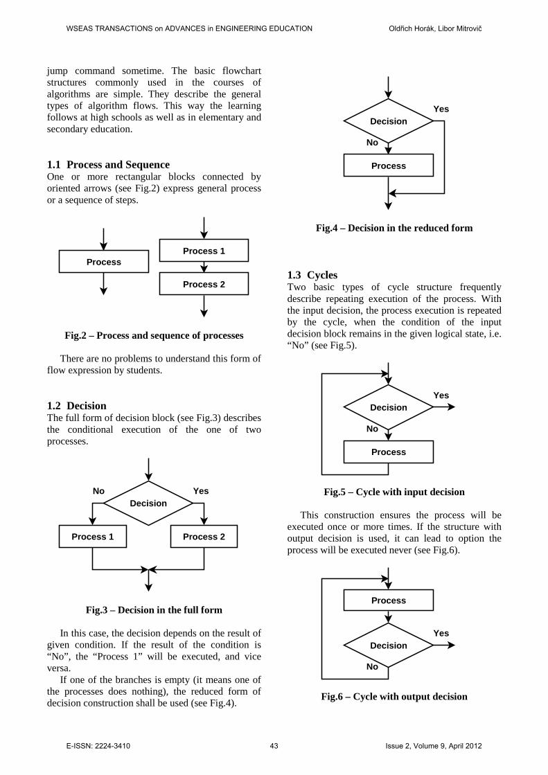
jump command sometime. The basic flowchart structures commonly used in the courses of algorithms are simple. They describe the general types of algorithm flows. This way the learning follows at high schools as well as in elementary and secondary education. 1.1 Process and Sequence One or more rectangular blocks connected by oriented arrows (see Fig.2) express general process or a sequence of steps.
ProcessProcess 1
Process 2
Fig.2 – Process and sequence of processes
There are no problems to understand this form of
flow expression by students. 1.2 Decision The full form of decision block (see Fig.3) describes the conditional execution of the one of two processes.
Decision
Process 1
YesNo
Process 2
Fig.3 – Decision in the full form
In this case, the decision depends on the result of
given condition. If the result of the condition is “No”, the “Process 1” will be executed, and vice versa.
If one of the branches is empty (it means one of the processes does nothing), the reduced form of decision construction shall be used (see Fig.4).
Decision
Process
Yes
No
Fig.4 – Decision in the reduced form
1.3 Cycles Two basic types of cycle structure frequently describe repeating execution of the process. With the input decision, the process execution is repeated by the cycle, when the condition of the input decision block remains in the given logical state, i.e. “No” (see Fig.5).
Decision
Process
Yes
No
Fig.5 – Cycle with input decision
This construction ensures the process will be
executed once or more times. If the structure with output decision is used, it can lead to option the process will be executed never (see Fig.6).
Decision
Process
Yes
No
Fig.6 – Cycle with output decision
WSEAS TRANSACTIONS on ADVANCES in ENGINEERING EDUCATION Oldřich Horák, Libor Mitrovič
E-ISSN: 2224-3410 43 Issue 2, Volume 9, April 2012

1.4 More Complicated Structures Some programming languages used to compile or interpret algorithms contain ability to use more complicated structures (i.e. some multiple-choice decisions, cycles for iteration through array or set). These structures can be expressed in flowchart using the combination of the basic structures, but the visual form loses its transparency primarily for beginners.
2 Problematic Structures The expression of more complicated structures using the basic blocks can be difficult to understand for the beginners. The common approach to keep the flowchart well formed is to take a care of observing the use of recommended structures. It means, the students have to use the basic structures and adapt their own creativity to the limited options of the used development environment. Therefore, students fall in feel the algorithm development is difficult and hardly understandable. 2.1 Multiple-Choice Decision The conditional execution of the processes in more branches can be simply expressed by concept of multiple-choice decision (see Fig.3). The processes are located in separate branches of the flowchart, and each one branch is tagged by the value of the result of the condition in the decision block.
Decision
1
Proc. 1
Proc. 2
Proc. 3
Proc. 4
Proc. 5
52 3 4
Fig.7 – Concept of Multiple-choice decision
But, such form of flowchart is not well formed
by the rules described in the introduction and generally observed. The recommended expression
of such type of decision requires the use of simple two-way decision blocks in cascade or other type of their arrangement (see Fig.8a and 8b) [4]. This type of rearrangement of the primary concept meets the common flowchart rules requirement, but the core of the primary concept is not evident at the first look. There is the collision between the common rules and ability to express the primary concept. It leads to problem for tutor to explain these fossilized rules well.
D2
D1
D3
D4
P1
P2
P3
P4 P5
Fig.8a – Well formed Multiple-choice decision
D2
D1
D3
D4
P1
P2
P3
P4
P5
Fig.8b – Other form of Multiple-choice decision
WSEAS TRANSACTIONS on ADVANCES in ENGINEERING EDUCATION Oldřich Horák, Libor Mitrovič
E-ISSN: 2224-3410 44 Issue 2, Volume 9, April 2012

2.2 Complicated Cycle The two basic types of cycle are recommended to use in flowchart. The difference is in the order of decision and process block in the cycle. But, in the reality, the cycles consist of more processes and decisions in general order (see Fig.9a and 9b).
Decision
Process 2
Yes
No
Process 1
Fig.9a – Cycle with decision in the middle
Decision 1
Process
Yes
No
Decision 2
No
Yes
Fig.9b – Cycle with two output decisions
If the more complicated cycle structures need to be coded with programming languages, the difficult fixes have to be made as the overwork. Such constructions are hardly understandable for the students and lead the thinking away from primarily solving algorithm [5, 6].
2.3 Common Structures The last type of structure can be common complex of processes and decisions connected using cyclic paths. Such structure can have more exit-points and even more entry-point. It is practically impossible to express such algorithms by any flowchart restricted by the well-form rules. But this type of processing loop occurs very frequently in the reality.
The rules of the well-formed flowchart structure make the algorithm development very hard in the eyes of students. It means, they feel it as a limited usability of flowcharts, or even as the limits of the algorithm development capabilities. This issue logically leads to the question, whether or not to use the flowchart to express the algorithms [6].
3 Solutions in Education Process The algorithm development courses are provided by schools of many types. There are some technically focused schools, where these courses serve as the background for related courses of programming and application development [8].
Other schools use the development of algorithm for to obtain the basic skill of problem identification and solution using graphical means of expression. The flowchart is then only the one of more types of diagram used to express some method or process in the time. 3.1 Using LEGO® The LEGO® MINDSTORMS® NXT-G is used at some schools to combine the algorithm development with robotics. It leads to higher interest of students in algorithms, programming and robotics in the form of play [1, 11].
The visual environment expresses the algorithms where the user drags and drops simple blocks on the sequence beam (see Fig.10) [1].
Fig.10 – Sequence beam with blocks [1]
All the algorithmic structures are designed to be user-friendly and easy to understand. The environment provides visual representation of all the electronic part of the LEGO® set.
WSEAS TRANSACTIONS on ADVANCES in ENGINEERING EDUCATION Oldřich Horák, Libor Mitrovič
E-ISSN: 2224-3410 45 Issue 2, Volume 9, April 2012

The SWITCH block splitting the one sequence beam in two branches (see Fig.11) expresses the decision feature.
Fig.11 –SWITCH block for a decision [1]
The more than two branches are possible to design by the SWITCH block in the form of tabbed view. The visualization of multiple-choice decision is easy realizable and don’t make any problem to understand by students [7, 8].
The LOOP block dropped at the sequence beam sets cycles (see Fig.12). The process in the cycle represented by the nested block is repeated continuously, and the end of the repeating can be realized only by some break condition. The loop is repeated forever in default setting, but more options can be used to break it.
Fig.12 – Empty LOOP block [1]
The using of this cycle is easy to understand, and the guide provided with the LEGO set describes it wells:
“What is a loop? In real life, a loop could be a road or a piece of string—no matter how large it is, if you follow its path, you’ll eventually come back to your starting position. A programming loop is very similar. It just circles back on itself, either forever or until you program an escape from the loop [1].”
The LOOP block can contain one or more blocks as the process blocks of the cycle structure (see Fig.13).
Fig.13 – A MOVE block inside a LOOP [1]
There are more options how to control the cycle by the setting of the LOOP block. The data from the sensors or additional information obtained from hardware of the LEGO set can be used to control the cycle flow.
More complicated tasks can be realized by two or more nested LOOP blocks. The control over such construction is as simple as over the one LOOP block. The guide explains it by the simple example (see Fig.14 and 15):
“This is called a nested loop, which just means a loop inside a loop. When the program runs, any blocks inside the outer LOOP block will run. First, the inner LOOP block will run three times (executing the MOVE and SOUND blocks inside it) and then break. Then the Light sensor will send a True/False Logic response to the outer LOOP block’s data plug. If the Light sensor does not detect a light level greater than 90, the outer LOOP block will not break and will run whatever is inside it again [1].”
WSEAS TRANSACTIONS on ADVANCES in ENGINEERING EDUCATION Oldřich Horák, Libor Mitrovič
E-ISSN: 2224-3410 46 Issue 2, Volume 9, April 2012

Fig.14 – More blocks inside nested LOOP blocks with output decision [1]
Fig.15 – More nested LOOP blocks with several output decisions [1]
The LEGO® MINDSTORMS® NXT-G provides not only the basics of the algorithm development, but the complex environment useful to set the good relation of students to the algorithms and programming [1, 7]. 3.2 Using Scratch Some schools use Scratch environment [3] to learn the basics of programming and algorithm development. The set of control structures is limited.
The reduced decision block relates to the standard block of flowchart (see Fig.16).
Fig.16 – Reduced decision block
WSEAS TRANSACTIONS on ADVANCES in ENGINEERING EDUCATION Oldřich Horák, Libor Mitrovič
E-ISSN: 2224-3410 47 Issue 2, Volume 9, April 2012
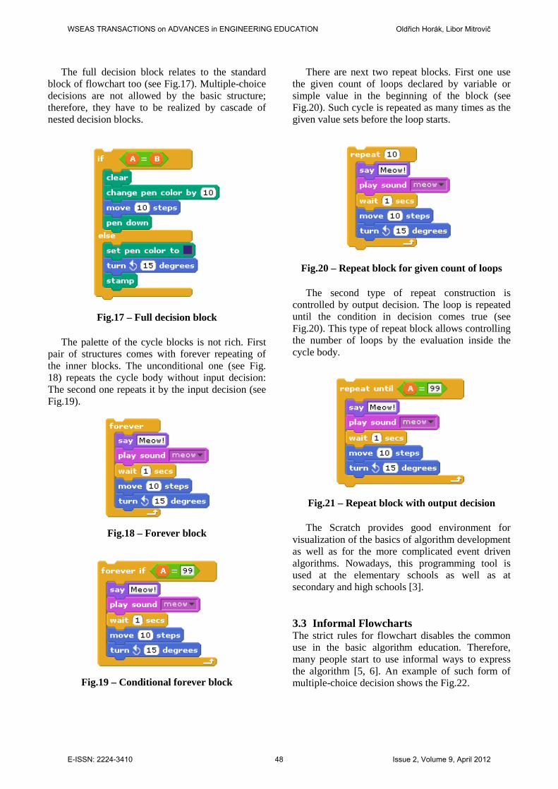
The full decision block relates to the standard block of flowchart too (see Fig.17). Multiple-choice decisions are not allowed by the basic structure; therefore, they have to be realized by cascade of nested decision blocks.
Fig.17 – Full decision block
The palette of the cycle blocks is not rich. First
pair of structures comes with forever repeating of the inner blocks. The unconditional one (see Fig. 18) repeats the cycle body without input decision: The second one repeats it by the input decision (see Fig.19).
Fig.18 – Forever block
Fig.19 – Conditional forever block
There are next two repeat blocks. First one use the given count of loops declared by variable or simple value in the beginning of the block (see Fig.20). Such cycle is repeated as many times as the given value sets before the loop starts.
Fig.20 – Repeat block for given count of loops
The second type of repeat construction is
controlled by output decision. The loop is repeated until the condition in decision comes true (see Fig.20). This type of repeat block allows controlling the number of loops by the evaluation inside the cycle body.
Fig.21 – Repeat block with output decision
The Scratch provides good environment for
visualization of the basics of algorithm development as well as for the more complicated event driven algorithms. Nowadays, this programming tool is used at the elementary schools as well as at secondary and high schools [3]. 3.3 Informal Flowcharts The strict rules for flowchart disables the common use in the basic algorithm education. Therefore, many people start to use informal ways to express the algorithm [5, 6]. An example of such form of multiple-choice decision shows the Fig.22.
WSEAS TRANSACTIONS on ADVANCES in ENGINEERING EDUCATION Oldřich Horák, Libor Mitrovič
E-ISSN: 2224-3410 48 Issue 2, Volume 9, April 2012

P2P1 P3
Dec.
12 3
Fig.22 – Repeat block with output decision
The decision block is realized by circle with pies for the given options from 1 to 3 connected to appropriate processes by the arrows.
Some schemes used for the complex system description come with the common cycles containing more processes and decisions.
These common loops can use more exit points set by the decision blocks, and more entry points marked by the input arrows and labels (see Fig. 23).
P1
P2
P3
En1En2
D1
D2
Fig.23 – Common cycle with more entry points
Fig.24 – More informal expression of process flow example [2]
WSEAS TRANSACTIONS on ADVANCES in ENGINEERING EDUCATION Oldřich Horák, Libor Mitrovič
E-ISSN: 2224-3410 49 Issue 2, Volume 9, April 2012

It is possible to use such type of algorithm for expression of general flow. Therefore, the informal flow schemes provide free hand and sufficient freedom to make a process or system description clear and understandable.
This type of charts can be used for description of examples as well as more complicated processes. The internal flow of the instruction processing i.e. in electronic components or chips can be expressed very well by this type of informal scheme (see Fig.24). 3.4 Programming Language Limitations The last step in the algorithm development process is to translate the flowchart or other used scheme to the programming language. The problems based on the features of the programming languages occur very often. The translation then requires specific skills to remake the code in the case when the programming language not contains appropriate statements for the given flowchart structures.
The explanation and clarification of such issue is the task for tutor. In example, the standardized Pascal programming language doesn’t contain the statement for the cycle with the output decision in the middle of the repeated process (see Fig.25a to 25c), and the developer has to shift the decision at begin or end of the cycle’s body. It is taken as the inconvenience by the students and leads to negative feels.
Fig.25a – While-do cycle in Pascal
Fig.25b – Repeat-until cycle in Pascal
Fig.25c – For cycle in Pascal
The only way is then the using of the flowchart rules related to the given programming language and to accept its limitations [6].
4 Conclusion and Future Work The algorithm development and the application programming course tutors use many tools to describe and explain the basic and advanced solutions of the given tasks.
There are many different types of algorithm description and expression. The students can be disappointed before they accept the basic knowledge of the structured algorithm development and application programming. In general, the basic courses can be lead by the rules of the standard flowchart, but they cannot be used for the more complicated problems solving. In such case, the expression dependent on the final programming language has to be used.
The complex analysis of the common features of the programming languages and design tools will be the future work. It will be used to design a complex common set of structure descriptions, which would take the role of general description language for algorithm development design, able to be easy translated to most programming languages. References: [1] J. F. Kelly, LEGO® MINDSTORMS® NXT-G
Programming Guide, Springer-Verlag New York, Inc., 2007.
[2] DS2480B Serial to 1-Wire Line Driver, Maxim Integrated Products, 2010.
[3] Lifelong Kindergarten Group, Scratch, MIT Media Lab, 2012, online: http://scratch.mit.edu/ (Retrieved on March 2nd, 2012).
[4] A. J. Blauch, P. D. Johnson, Structured Design using Flowchart, Grand Valley State University, 2001.
for counter setting do begin process 1 process 2 end;
repeat process 1 process 2 until condition;
while condition do begin process 1 process 2 end;
WSEAS TRANSACTIONS on ADVANCES in ENGINEERING EDUCATION Oldřich Horák, Libor Mitrovič
E-ISSN: 2224-3410 50 Issue 2, Volume 9, April 2012
[5] W. S. Davis, D. C. Yen, The Information System Consultant's Handbook: Systems Analysis and Design, CRC Press, 1998.
[6] H. Jack, Automating Manufacturing Systems with PLCs, Grand Valley State University, 2010.
[7] M. Pisciotta, B. Vello, C. Bordo, and G. Morgavi, Robots as learning tools in a vocational school, in WSEAS Transactions on Advances in Engineering Education, Issue 4, Volume 7, 2010, pp. 129-138.
[8] S. Jun, S. Kim, W. Lee, Teaching Strategy for Algorithmic Problem-Solving, in WSEAS Transactions on Advances in Engineering Education, Issue 11, Volume 7, 2010, pp. 371-380.
[9] R. M. Majzub, M. Ysuf, Investigating Relationship between Self-efficancy Achievement Motivationa and Learning Straegies of UKM Undegraduated Students, in Proceeding of the 6th WSEAS International Conference on Advanced Educational Technologies, 2010, pp. 187-190.
[10] A. J. Viamonte, The Computer in the teaching of mathematics in Proceeding of the 6th WSEAS International Conference on Advanced Educational Technologies, 2010, pp. 24-29.
[11] R. Goldman, A. Eguchi, and E. Sklar, Using educational robotics to engage inner-city students with technology, in Proceedings of the 6th international conference on Learning sciences, 2004, pp. 214–221.
WSEAS TRANSACTIONS on ADVANCES in ENGINEERING EDUCATION Oldřich Horák, Libor Mitrovič
E-ISSN: 2224-3410 51 Issue 2, Volume 9, April 2012