design a method for detecting the inconsistent loops in the … · · 2015-08-11specification of...
TRANSCRIPT

Design A Method for Detecting the Inconsistent Loops in the Specification of Multimedia Hyper-Presentation Using Petri-Net
Jong-Keun Cho*, Si-Yeon Woo*, Younghwan Lim*, Hak-Young Kim**
*Department of Computing Soongsil University SangDo-Dong DongJak-Ku, Seoul, Korea [email protected] **Computer System Section, ETRI 161 Gajeong-Dong, Yuseong-Gu, Daejeon, Korea [email protected]
Abstract. This paper introduces the method of describing the hyper-presentation using Petri-Net and proposes the method of detecting inconsistent hyper-link loop in the hyper-presentation description. The concept of a hyper-presentation, as an extension of a hypermedia, is the presentation in which time-varying multimedia presentations are dynamically linked together and a hyperlink’s context can be changed over time at any time during a continuous presentation. For the purpose of detecting such inconsistent hyper-linked loop, we propose Multi Dimensional Timed Petri-Net Model for specification of a multimedia hyper-Presentation. Then, based on the model, two methods, one for detecting the inconsistent loop and the other for finding the critical path for the actual presentation of the hyper-Presentation specification are described.
Keywords: Petri-Net; Hyperlinks; Hyperlink loop; Multimedia Received 28 Jan. 03; Revised and accepted 28 Feb. 2003
1 Introduction
Multimedia system has been focused on the method of synchronization mainly centered on the sequential presentation of media streams up to now.
The method of describing the timed synchronization for multimedia presentation includes Time Axes-based Specification that specifies media presentation time at global-time, and Interval-based Specification that specifies temporal priority by describing relationships between media to present[2,5,6,8,12]. In addition to such existing method of synchronized presentation, this paper proposes a new synchronized specification for hyper-presentation.
The concept of a hyper-presentation is an extension of a hypermedia concept to existing multimedia presentation. That is, it is not a sequential multimedia presentation, but it enables time-varying multimedia presentation to see the next information required at a specific point by setting hyperlink.
While synchronized method in hyper-presentation enables flexible presentation, inconsistency problems can be introduced in between several presentations connected by such synchronized method. This paper proposes, as a solution of this problem, the algorithm for verification of consistency after modeling hyper-presentation specification program with Petri-Net and also proposes the algorithm to judge Critical Path affecting the presentation QoS(Quality of Service) of hyper-presentation.
2 Hyper-presentation Model
2.1 Example of Hyper-presentation News Casting Scenario
Here’s a news casting exercise for an example of hyper-presentation as shown in the Figure 2. The presentation clips, prs1, prs2, prs7, and prs10 are configuration of the news casting and these
Journal of Digital Information Management Vol. 1 No. 1 March 2003 20

become the main streams. And the presentations containing the report on the event or weather forecast during the news are connected in sequence.
• prs1:Starting comment of a anchorman • prs2:Explanation on speech field for an election of an assembly member and closing
comment after prs3, 4, 5, and 6 end. • prs3:Speech Scene of Candidate A • prs4:Detailed explanation on Candidate A • prs5:Speech Scene of Candidate B • prs6:Detailed explanation on Candidate B • prs7:Report on the next event and closing comment after prs8 and 9 end • prs8:Explanation on the event by reporter • prs9:Circumstance screen of the event • prs10:Weather forecast for tomorrow and news closing comment after prs11 and 12 • prs11:Regional Weather forecast • prs12:Weekly weather forecast
The following Figure 1 shows a specification hyper-presentation using the above presentation clips.
2.2 Synchronized specification Method for hyper-presentation
Here the mechanisms for describing hyper-presentation are introduced.
2.2.1 Global LTS (Logical Time System)
Logical Time System (LTS), as a timing method for synchronization of streams, can determine the unit time by adjusting internal tick interval.
The Figure 2 is a hyper-presentation whose start time and end time are set on LTS time axes. Presentation A starts at LTS 300 and ends at 500. Also presentation B starts at LTS 400 and ends at 800. Seeing from the point between LTS 400 and 500, both presentation A and B are performed simultaneously, but they have an independent relation respectively.
Journal of Digital Information Management Vol. 1 No. 1 March 2003 21

A
B
300 400 500 800 LTS
“Figure 2” Time Axes-based Specification
2.2.2 Cue
The existing Interval-based Specification [7,12] matched synchronization by defining temporal relationships between media with Before, After, Starts, Finishes, Overlaps, During, Meets, Equals, Before-1, After-1, Starts-1, Finishes-1, Overlaps-1, During-1, and Meets-1. Difference of CUE from LST is that cue is set by specifying temporal relationships of the presentation A and B as shown in the Figure 3 below.
2.2.3 Hyper-Link
When applying extension of hypermedia concept to the existing sequential multimedia presentation, the presentation currently being performed should temporarily suspend, perform the other presentation and then resume the original presentation. Hyper-link is defined with three elements as described below.
(1) Location
Journal of Digital Information Management Vol. 1 No. 1 March 2003 22
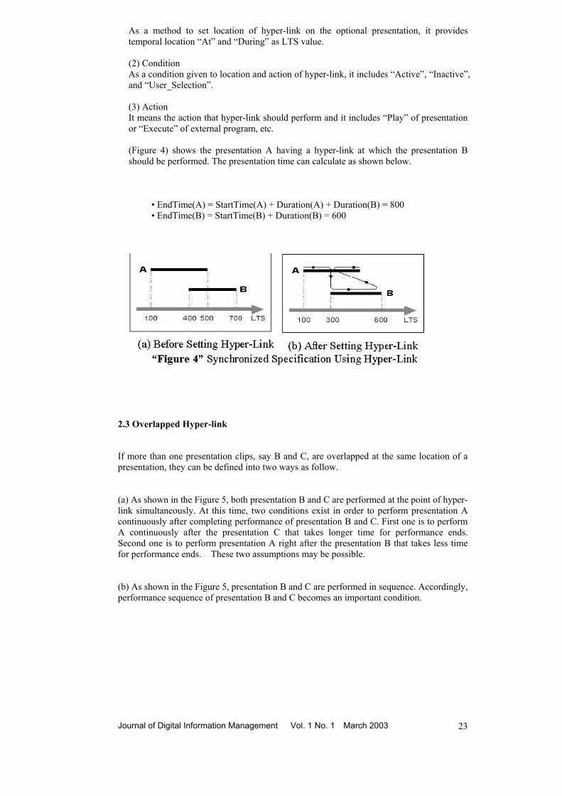
As a method to set location of hyper-link on the optional presentation, it provides temporal location “At” and “During” as LTS value. (2) Condition As a condition given to location and action of hyper-link, it includes “Active”, “Inactive”, and “User_Selection”. (3) Action It means the action that hyper-link should perform and it includes “Play” of presentation or “Execute” of external program, etc. (Figure 4) shows the presentation A having a hyper-link at which the presentation B should be performed. The presentation time can calculate as shown below.
• EndTime(A) = StartTime(A) + Duration(A) + Duration(B) = 800 • EndTime(B) = StartTime(B) + Duration(B) = 600
2.3 Overlapped Hyper-link
If more than one presentation clips, say B and C, are overlapped at the same location of a presentation, they can be defined into two ways as follow.
(a) As shown in the Figure 5, both presentation B and C are performed at the point of hyper-link simultaneously. At this time, two conditions exist in order to perform presentation A continuously after completing performance of presentation B and C. First one is to perform A continuously after the presentation C that takes longer time for performance ends. Second one is to perform presentation A right after the presentation B that takes less time for performance ends. These two assumptions may be possible.
(b) As shown in the Figure 5, presentation B and C are performed in sequence. Accordingly, performance sequence of presentation B and C becomes an important condition.
Journal of Digital Information Management Vol. 1 No. 1 March 2003 23

Journal of Digital Information Management Vol. 1 No. 1 March 2003 24
2.4 Synchronization between Presentations
Hyper-presentation can specify synchronization between presentations with LTS, cue and hyper-link and they form Relative-Time axes.
In a Figure 6, presentation A is set as “Before” cue to presentation B and it is bound to its relationship. Also presentation C is connected to presentation B by hyper-link. Therefore, that presentation performed on the basis of wide area time axes are only B and D.
2.5 Problems
The Figure 7 shows hyper-presentation that prepared news casting scenario by using VIP (Visual Interface Player).
A
B
C
A
B C
(a) Parallel Processing (b) Sequential Processing “Figure 5’ Overlapped Hyper-Link
“Figure 7” News Casting Scenario Prepared by VIP

Though the presentations are prepared to be synchronized presentation according to the settings of scenario, it may not be presented as the user has intended when occasion demands. When preparing hyper-presentation specification program, it often becomes impossible to actually present. Such problem is caused from consistency error of the specification program, that is, though the user specified synchronization of the presentations, the cycle that was not intended by the presentations occurs and the presentations may be infinitely repeated or not performed at all. Therefore, finding and solving such cycles prior to presentation is to maintain consistency of the hyper-presentation. 2.6 Related Study
2.6.1 Petri-Net Model
2.6.1.1 Definition of Petri-Net
Petri-Net was introduced for the first time in a thesis for a doctorate prepared by Dr. C. A. Petri in the University of Born in Germany in 1962 and it is a graphic and mathematical modeling tool designed to study the features of concurrent or parallel processes on a system. Petri-Net model is defined by tuple such as P, T, F, and B, and each attribute is as follows in [3,4].
• P is a finite set of places.
P ={p1, p2, p3, …, pm }, P≠φ • T is a finite set of transitions.
T ={t1, t2, t3, …, tm }, T ≠φ, P∩T ≠φ • F is forward incidence function. • B is backward incidence function. • µ0, as initial marking, indicates initial state.
2.6.1.2 Petri-Net Graph
Petri-Net was developed as a modeling tool describing the concurrent or parallel processes on a system. Process may suppose to be configured of condition, events, and rule that describes relationship between them. These condition and events are described with place (mark with circle) and transition (mark with segment or box) in Petri-Net graph respectively.
2.6.2 Synchronized Specification using Petri-Net
2.6.2.1 Temporal Relationships Model
Allen[7] defined it with seven(7) relationships describing time interval between two object in his study and the next is a figure described temporal relationship in such Interval-based Specification with Petri-Net [5,6,9,12].
2.6.2.2 UI Description using Petri-Net
The (Figure 8) below is an example of synchronization described Time Axes-based media data and User Interaction, and (Figure 9) is an example of modeling this with Petri-Net [2,8,12]. Journal of Digital Information Management Vol. 1 No. 1 March 2003 25

S R P
A1 A2 A3
UI P4
Audio-VideoSubnet
60s 15s20s
PictureSubnet
RecordUI
AuAnimationSubnet1
AnimationSubnet3
Animation Subnet2and Audio Subnet
User Interaction Closing picture
“Figure 9” Synchronized Specification using Petri-Net
3 Modeling of Hyper-presentation Specification Program using Petri-Net
3.1 Definition of Multidimensional Timed Petri-Net (MTPN) Model
Multi-dimensional TPN is defined by extending the existing Timed Petri-Net for modeling of multi-dimensional hyper-presentation as follows:
[Definition 1] Multi-dimensional Timed Petri-Net
MTPN C = ( P, T, F, B, µ0, τ, ε )
• P = {p1, p2, p3, …, pm }, P ≠ φ • T = {t1, t2, t3, …, tm }, T ≠φ, P∩T = φ • F:P x T → N(Except, N is an integral set except negative number) • B:P x T → N • µ0:P → N • τ → N • ε:P → N
Petri-Net model consists of a 7-tuple such as a finite set P of place, a finite set T of transition, backward incidence function B, forward incidence function F, initial marking µ0, time function τ, state function ε.
Journal of Digital Information Management Vol. 1 No. 1 March 2003 26

In marking µ in which Transition tj � T are given, if it is µ (pi) ≥ F(pi , tj) for all pi � P, tj is described as ignitable transition for marking µ. Also the set E(µ) of all ignitable transitions for the optional marking µ is called ignitable set for marking µ. At this time, tj �E(µ)�� pi � P, µ (pi) ≥ F(pi , tj) is formed. If current marking is µ and transition tj � T are ignitable transitions, next marking µ’ is defined as follows. At this time, marking µ’ is called to be attainable from marking µ.
(∀ pi ∈ P) µ’ (pi) =µ (pi) – B(pi , tj ) + F(pi , tj ) 3.1.1 Time Function of MTPN Model
Time function τ describes time condition given to each transition. Next is the definition of time condition in the existing Timed Petri-Net. Carlier[13] proposed firing executing time as a time condition of Timed Petri-Net and it indicates the time from starting firing time to ending firing time. Removal of token from input place due to firing of ti occurs in starting firing time (ts) and addition of token to output place occurs ending firing time (ts + f j) [10,11,13]. This paper defined actual waiting time of transition as a time condition of MTPN model and (Figure 10) shows application of duration of presentation to this. ∀(pi , tj ) ∈ (P×T), τ (tj ) = Duration(pi) = dj
t i m eta tctetstb
dj
tj**tj*
fj
• ta : logical starting firing time by TPN model • tb : logical starting firing time by by system • ts : starting firing time • te : ending firing time • tc : ending firing limit point allowed by system • tj
* = tb- ta : minimum wating time • tj
** = tc- ta : maximum allowed time • fj = te- ts : firing execution time • db = ts- ta : duration of presentation
“Figure 10”. Time Condition in Timed Petri-Net Model
3.1.2 State Function of MTPN Model
Event has a time domain different from description of a presentation and it is impossible to presuppose occurrence of an event. Therefore, this paper defines state function ε for modeling multi-dimensional hyper-presentation as follows. At this time, Ro is a positive real number set including 0 and ∞.
ε (pi) = e (pi ∈ P, e ∈ R0, 0≤e≤ τ (tj)) Here, e, as the time that an event occurred, can occur in the entire section of description of a presentation. Therefore, state function ε indicate the time to resume the original presentation after completing a performance by event.
3.2 Modeling of Synchronized Specification Program using MTPN
When taking a presentation for an object and specifying synchronization between the objects, description of a hyper-presentation is available without any affect from media stream configuring the presentation or synchronization between them. If a presentation is
Journal of Digital Information Management Vol. 1 No. 1 March 2003 27

described with a place, the place containing a token can consider as a currently performing presentation. Therefore, firing from input place to output place means performance of next presentation following right after the completion of currently performing presentation. Thus, description of a hyper-presentation is possible as shown in the (Figure 11).
A
B C D
E
Hyperpresentation
dc
e
Presentation
f
Presentation
Audio, Video, ...
a
b
“Figure 11” Modeling of Hyper-Presentation Using MTPN
3.2.1 Modeling Cue
Cue describes synchronization by specifying temporal relationships between two presentations. Next (Figure 12) shows a configuration of a hyper-presentation by specifying temporal priority of the presentations connected with cue.
A
C
BQ1
Q2
“Figure 12” Synchronization between Presentations Connected with Cue
Next (Figure 13) shows a modeling of a synchronized specification with MTPN as (Figure 12), and <Table 1> is the formula to calculate starting time of sub-presentation that is synchronized by relationship of cue.
Journal of Digital Information Management Vol. 1 No. 1 March 2003 28

A
B
t1 Ct2
“Figure 13” Time Relationship Model of Cue Using MTPN
<Table 1> Calculation Formula of Starting Time of Sub-presentation
according to Relationships of Cue
Attribute of Cue Starting Time of Sub-Presentation A Start (t) B StartTime(B) = StartTime(A) + t
A Finish (t) B StartTime(B) = EndTime(A) - Duration(B) - t A Before (t) B StartTime(A) = StartTime(B) - Duration(A) - t A After (t) B StartTime(A) = EndTime(B) + t
3.2.2 State Function of MTPN Model
A hyper-presentation provides multi-dimensional multimedia description method. The method to set event point on a presentation; • If time value by LTS is set to event point • If hot-spot on consecutive media is set to event point
A
C
BD
“Figure 14” Synchronization between Presentations Connected with Hyper-Link
This paper proposes modeling method of such hyper-link concept using MTPN. (Figure 14) shows synchronization between presentations connected with hyper-Link. (Figure 15) shows a modeling of hyper-presentation in (Figure 14) with MTPN. The place called ”Event” was added for this modeling in order to describe Hyper-Link.
Journal of Digital Information Management Vol. 1 No. 1 March 2003 29

A
B
C
D
Event
Event
“Figure 15” Modeling of Hyper-link using MTPN
Event point is available of static setting by LTS and also dynamic setting by hot spot. An event (UI) by the user is also a dynamic setting during description. Such events occur with different time domain from description of presentation and temporal presupposition is difficult. Also if an event occurs, presentation A should temporarily suspend at this time and resume description of A again after performing presentation B. Thus a dynamic model executed in run-time is required. (Figure 16) shows, as a dynamic model described this, a dynamic execution model from “Static Description Model” into “Dynamic Execution Model”.
A1
B
A2
A
B
Event
T2
T1
“Figure 16” Dynamic Execution Model
3.2.3 Modeling of a New Casting Scenario
The Figure 17 shows a modeling of a news-casting example in (Figure 7).
Journal of Digital Information Management Vol. 1 No. 1 March 2003 30

Event
Event
prs1
prs2
Eventprs3
prs5
Eventprs4
prs6
prs7
prs8 prs9
Event prs10
prs11
prs12
“Figure 17” Modeling of a News Casting Scenario
4 Verification of Consistency in Hyper-presentation Specification Program
4.1 Inconsistency Problem in Synchronized Specification Program
Though the user specified synchronization of the hyper-presentations, the cycle that was not intended by the presentations occur and the presentations may be infinitely repeated or not performed at all. Therefore, finding and solving such cycles prior to presentation is to maintain consistency of the hyper-presentation. This paper proposes, as a solution of this problem modeling hyper-presentation specification program with MTPN for advance judgment on describability of given hyper-presentation and also proposes the algorithm to find Critical Path in the hyper-presentation that specified QoS requirements because sometimes synchronization of hyper-presentation may not be properly made or QoS of multimedia presentation is deteriorated due to the feature of multimedia presentation and network problem.
4.2 Inconsistency Problem in Synchronized Specification Program
4.2.1 Modeling of Synchronized Specification Program using MTPN
When specifying synchronization between presentations with Cue or Hyper-link, inconsistency problem that cycle occurs is the same in the model that described this (synchronization) with MTPN. Therefore, consistency in specification program can verify by detecting the cycle in MTPN Model. Next (Figure 18) shows occurrence of cycle in connection of cue.
prs1
prs3
prs2Q1
Q3
Q2
“Figure 18” Cycle in Connection
Journal of Digital Information Management Vol. 1 No. 1 March 2003 31

Viewing from the figure above, the cycle occurs when prs1 and prs3 are connected with cue (Q3). Starting time and ending time of prs1 varies according to relationship (Finish) of cue. Seeing from Q1connection again, the starting time and ending time of prs2 is changed because the starting time of the standard presentation prs1 was changed. Similarly, seeing from Q2 connection, starting time and ending time of prs3 are also changed because the starting time of standard presentation prs2 was changed. Accordingly, the result that time value of prs1 by Q3 is continuously repeated. Next (Figure 19) shows a model of hyper-presentation in (Figure 18) with MTPN and it is easy to know that the cycle occurs between the presentations due to connection of cue.
t1
prs2
t2
prs1
prs3t3
“Figure 19” Modeling of Cue using MTPN The Figure 20 shows occurrence of cycle between presentations due to hyper-link set to presentation.
prs1
prs3
prs2
“Figure 20” Cycle in Hyper-Link Connection Viewing from (Figure 20), the cycle occurs when a dynamic performance of prs1 was intended by setting hyper-link to prs3. (Figure 19) that is a modeling with MTPN shows occurrence of cycle between the presentations and (Figure 21) also shows that the cycle occurs when the modeling was described with MTPN. Therefore finding the part that cycle occurs in advance is to prevent occurrence of serious problem to a system. Journal of Digital Information Management Vol. 1 No. 1 March 2003 32

prs1 Event
prs2 Event
prs3 Event
“Figure 21” Hyper-Link Modeling Using MTPN
4.2.2 Algorithm to detect cycle on MTPN Model
In definition of MTPN C=(P,T,B,F, µ0, τ, ε), the set of place P is described as follows.
P = {p1, p2, p3, …, pm} Also when describing place and transition with node s respectively, the set of following nodes (successor) can define as follows:
so = {v∈ P∪T, (s,v)∈(P x T)∪(T x P)} If s is place, so is the output transition set of s, and on the contrary, if s is transition, so is the set of output places. Therefore, so is described as follows: So = {Г (s,1), Г (s,2), …, Г (s,|so|)} Pi-1 ={p1, p2, p3, …, p i-1 } Here, Г (s,i) is the i-th following nodes(successor) of s. On the basis of such description, this paper proposes the algorithm to detect cycle on a MTPN Model. 1. [Initialize the set of circuits] C = φ. 2. [For i = 1 to n, compute the set of circuits that contain place pi but do not contain any place belonging Pi-1 ={p1, p2, p3, …, pi-1 }. For this purpose, consider the set of elementary paths starting from pi. Let wj be the j-th node of γ. i.e. γ = {w1, w2, … w|r| } and let wj+1 be the k[j]-th successor of node wj, i.e. wj+1 = Г (wj , k[j]).] 2.1 Initialize:γ = {pi}, k[1] = 0 2.2 while γ≠ φ, do 2.2.1 k[|γ| ] = k[|γ| ] + 1
Journal of Digital Information Management Vol. 1 No. 1 March 2003 33
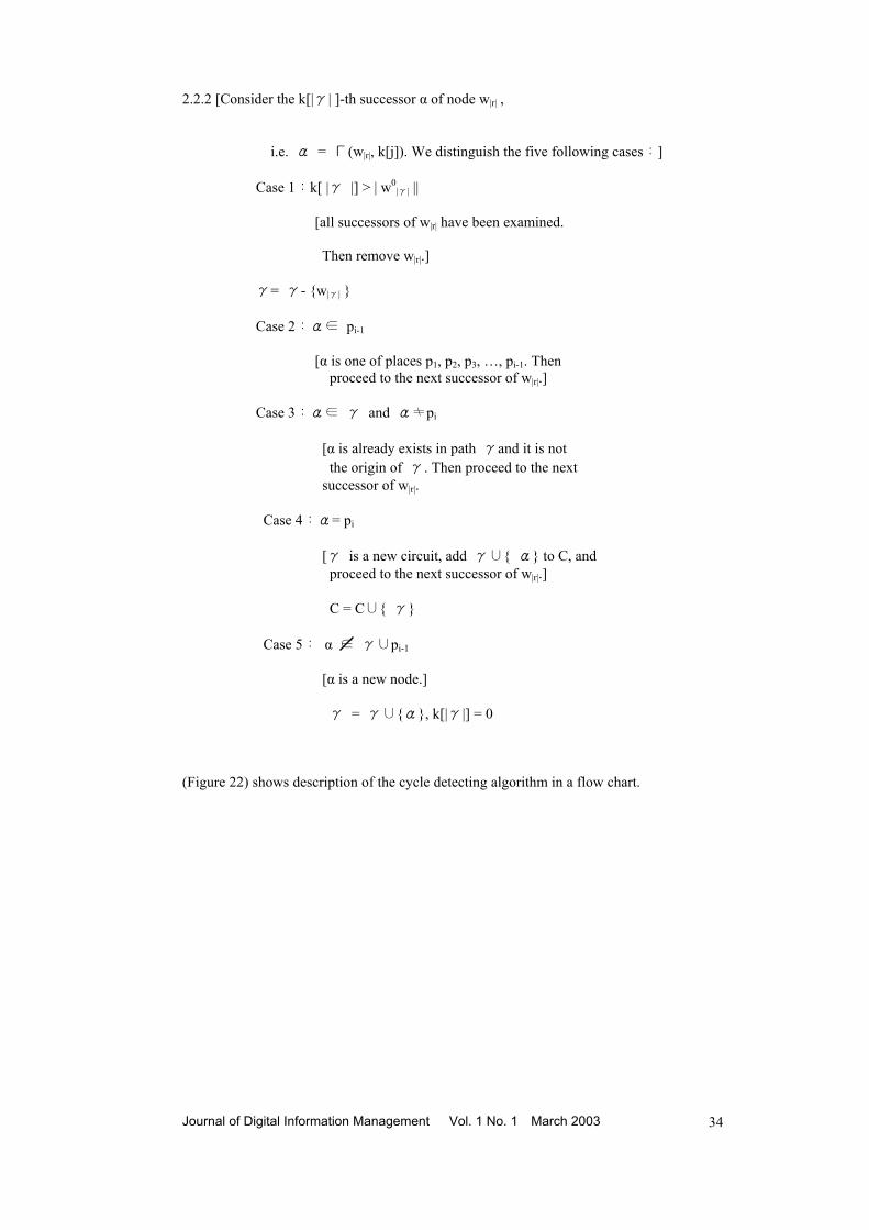
2.2.2 [Consider the k[|γ| ]-th successor α of node w|r| , i.e. α = Г(w|r|, k[j]). We distinguish the five following cases:] Case 1:k[ |γ |] > | w0
|γ| || [all successors of w|r| have been examined. Then remove w|r|.]
γ= γ- {w|γ| }
Case 2:α∈ pi-1
[α is one of places p1, p2, p3, …, pi-1. Then proceed to the next successor of w|r|.] Case 3:α∈ γ and α≠pi
[α is already exists in path γand it is not the origin of γ. Then proceed to the next successor of w|r|. Case 4:α= pi [γ is a new circuit, add γ∪{ α} to C, and proceed to the next successor of w|r|.] C = C∪{ γ} Case 5: α ∈ γ∪pi-1
[α is a new node.] γ = γ∪{α}, k[|γ|] = 0 (Figure 22) shows description of the cycle detecting algorithm in a flow chart.
Journal of Digital Information Management Vol. 1 No. 1 March 2003 34

C = ∅
i = 1
γ = { pi}k[1] = 0
γ ≠ ∅
k[|γ|] = k[|γ|] + 1α = Γ(ω|γ|, k[|γ|])
k[|γ|] > |ω|γ|° |
γ = γ − {ω|γ|}
α ∈ Pi-1
α ∈ γ&
α ≠ pi
α = pi
γ = γ ∪ {α}C = C ∪ {γ }
α ∉ γ ∪ Pi-1
γ = γ ∪ {α}k[|γ|] = 0
i = i + 1 i ≤ n STOP
Yes
No
Yes
Yes
Yes
Yes
No No No
No No
Yes
Yes
“Figure 22” Cycle Detecting Algorithm in a Flow chart
To detect cycle on a MTPN Model, allocate the set of place P that is executed first to time function τ between the presentations and every time when the time function τ moves one by one, put this value to wj the set element of time function ( that is, the result value α acquired from comparison of (j and k[j]. And the cycle detecting algorithm proposed above can detect cycle by applying Г (DELTA), that is, with 5 cases as shown in the formula (j+1 = Г ((j, k[j]). Also it can detect the other cycle by increasing time function one by one after detecting the cycle. And the condition to detect cycle is C=φ.
4.3 Critical Path in Hyper-presentation
Mostly duration limit for given network transmission cannot know and that the most realistic time is set to representative value for the duration by using statistic method and then transmission schedule for all packets are prepared on the basis of this. Therefore, it is required to judge Critical Path in order to guarantee the quality of multimedia presentation.
4.3.1 Critical Path Judgment Algorithm
This paper intends to take the QoS requirements of the user on the place, that is, presentation in a hyper-presentation specification program using Petri-Net from the user and then judge critical path in hyper-presentation on the basis of this. The followings are definitions of critical path judgment algorithm and the terms used for this. • S:start place • E:end place •QoS(p):QoS of place p • PP(p):previous place set of p
Journal of Digital Information Management Vol. 1 No. 1 March 2003 35

• N(p):number of element of PP(p) • A(p):max{A(PARENT(p)) + QoS(p)}
1. [ This step initializes a variable N(p) to id p for every place p ≠ S.
The variable N(p) will be used to count the number of places adjacent to p that have not yet been labeled.] For every place p ≠ S, let N(p) = the number of PP(p).
2. [ A queue Q is initialized] Q = φ. 3. [ This step labels S and updates N(p) for all places p adjacent from S. Further, those
places p for which N(p) = 0 are added to Q, which consists of places that are ready to be labeled.]
3.1 A(S) = 0. 3.2 For every place p such that S ∈ PP(p), let N(p) = N(p) - 1, PARENT(p) = S and add p to Q. 4. [ This step deletes a place q from Q, labels q, determines PARENT(q), updates N(p) for all places p adjacent from q, and adds to Q those places
p for which N(p) = 0.] let N(p) = N(p) - 1. If N(p) = 0, then add p to Q. 5. [ This step determines whether T has been labeled.] If T has been labeled, then continue;Otherwise, return to Step 4. 6. [ This step finds a critical path in PN.] 6.1 CP:T = p0 . 6.2 k = 0. 6.3 [ Suppose that CP : pk , pk-1,•••• p1, p0 has been determined, where Pi = PARENT( pi-1 ) for 1 ≤I ≤K. Then this step determines whether CP is already a critical path. If we have not
yet found a critical path, then this step extends P.] If pk = S, then output CP and A(T), and stop. Otherwise, let pk+1 = PARENT( pk ) and CP:pk , pk-1,•••• p1, p0. 6.4 k = k+1 and return to Step 6.3. Critical Path means the link with the high possibility to cause bottleneck due to the most serious consumption of resources. Generally the packets transmitted with the longer duration than the set duration value cannot be presentation at the required time and so they are processed as loss packet. The more the loss packet, the quality of presentation deteriorates. Therefore, it is very important to prepare transmission schedule to minimize loss packet as many as possible. Critical Path algorithm shown above grants id to the p’s of previous places in the set of place p first, give label to executing place (S) and then change the p value of previous place around there. If the changed p value of previous place is the element of S, it decreases one by one to process all the values contained in Queue and decide paths and then fine critical path among these paths.
5 Conclusion
This paper intended to make advance judgment on the describability of given hyper-presentation by modeling hyper-presentation specification program with Petri-Net and Journal of Digital Information Management Vol. 1 No. 1 March 2003 36
defined MTPN in order to judge the possibility to describe hyper-presentation and performed modeling of synchronized specification program using this model. Also it proposed the algorithm to detect cycle on a MTPN model of hyper-presentation that can verify consistency in synchronized specification program. In addition, it proposed the algorithm to judge Critical Path on a MTPN model in order to judge the possibility to describe hyper-presentation that considered QoS requirements of user and the capacity of actual resources.
References
1. Y.H.Lim. (1996). ComBiStation : Computer Platform for Distributed Multimedia
Computing Environment, Korea Information Sceince Society, 2(1), 6-8. 2. Patrick Senac, Michel Diaz, Alain Leger and Pierre de SaqueSannes. (1996). Modeling
Logical and Temporal Synchronization in Hypermedia Systems, IEEE Journal on Selected Areas in Communications, 14(1), 94-103.
3. M. Ajmone Marsan, G. Balbo and G. Conte. (1993). Modeling with Generalized Stochastic Petri-Nets, WILEY.
4. T. Murata. (1989). Petri-Nets : Properties, Analysis and Applications, Proceedings of the IEEE, 77(4), 541-576.
5. Thomas D. C. Little and Arif Ghafoor. (1993). Interval-Based Conceptual Models for Time-Dependent Multimedia Data, IEEE Transactions on Knowledge and Data Engineering, 5(4), 551-563.
6. Ralf Steinmetz. (1990). Synchronization Properties in Multimedia Systems, IEEE Journal on Selected Areas in Communications, 8(3), 401-412.
7. J. F. Allen. (1983). Maintaining Knowledge About Temporal Intervals, CACM, 26(11), 832-843.
8. S. V. Raghavan and B. Prabhakaran. (1994). Synchronization Models for Multimedia Presentation with User Participation, ACM/Springer-Verlag Multimedia Systems, 2(2), 53-62.
9. M. Hack. (1975). Decidability Questions for Petri-Nets, Ph.D. dissertation, MIT, Massachusetts.
10. Stephen S. Yau and Mehmet U. Caglayan. (1983). Distributed Software System Design Representation Using Modified Petri-Nets, IEEE Transactions on Software Engineering, Vol. SE-9(6), 733-745.
11. Bernard Berthomieu and Michil Diaz. (1991). Modeling and Verification of Time Dependent Systems Using Time Petri-Nets, IEEE Transactions on Software Engineering, 17(3), 259-273.
12. G, Blakowskiand and R. Steinmetz. (1991). A Media Synchronization Survey:Model, Specification, and Case Studies, IEEE Journal on Selected Areas in Communications, 14(1), 5-35.
13. J. Carlier, P. Chretienne and C. Girault. (1985). Modelling Scheduling Problems with Timed Petri-Nets, in:Advanced in Petri-Nets 1984, Lecture Notes in Computer Science, Springer-Verlag, 62-82.
Journal of Digital Information Management Vol. 1 No. 1 March 2003 37