design, analysis and manufacturing of carbon fibre rims
TRANSCRIPT

K. J. SOMAIYA COLLEGE OF ENGINEERING
Team ETA
Design, Analysis and
Manufacturing of Carbon
Fibre Rims GROUP NO : 76
BIREN CHAUHAN – 1525001
ALIASGAR MOHAMMEDI - 1525010
2
Table of Contents
Abstract …………………………………………………………………………………………………… 4
1. Introduction …………………………………………………………………………………….. 5
1.1 Background ………………………………………………………………………………… 5
1.2 Purpose ………………………………………………………………………………………. 5
1.3 Aims …………………………………………………………………………………………… 6
1.4 Boundaries ………………………………………………………………………………….
6
2. Literature review ……………………………………………………………………………. 7
2.1 Hub …………………………………………………………………………………………….. 7
2.2 Spokes ………………………………………………………………………………………… 7
2.3 Rim …………………………………………………………………………………………….. 8
2.4 Composite material ……………………………………………………………………..
8
3. Summary of literature review …………………………………………………………..
10
4. Methodology …………………………………………………………………………………… 11
4.1 Design …………………………………………………………………………………………… 12
4.1.1 Esthetics & ergonomics ………………………………………………………… 12
4.1.2 Hub design ……………………………………………………………………………. 13
4.1.3 Mould design ………………………………………………………………………… 14
4.2 Analysis …………………………………………………………………………………………. 15
4.2.1 Mesh view ……………………………………………………………………………. 17
4.2.2 Total shear stress ………………………………………………………………….. 18
4.2.3 Total deformation …………………………………………………………………. 18
4.2.4 Applying loading condition ……………………………………………………. 19
4.2.5 Total deformation …………………………………………………………………. 19
4.2.6 Applying air pressure …………………………………………………………….. 20
4.2.7 Meshing of Disc …………………………………………………………………….. 20
4.2.8 Ansys composite processor (ACP) …………………………………………. 21

3
4.3 Manufacturing ………………………………………………………………………………. 22
4.3.1 Mdf pattern …………………………………………………………………………… 22
4.3.2 Aluminium mould using Sand Casting procress ……………………… 22
4.3.3 Machining of Casted mould for finishing cut on VMC ……………. 23
4.3.4 Manufacturing of CF Disc from mould …………………………………… 23
4.3.5 Hub machining on CNC Lathe ………………………………………………… 24
4.3.6 Assembly of Disc and Hub using Loctite as bonding agent …….. 24
4.4 Testing ……………………………………………………………………………………………
24
5. Expected conclusion ………………………………………………………………………….
25
6. Future scope …………………………………………………………………………………….
25
7. Bibliography ……………………………………………………………………………………..
26
8. Acknowledgement ……………………………………………………………………………
27
4
ABSTRACT
Motivated by the persistently pursued weight reductions in a vehicle projected for a fuel
efficiency competition, this project deals with designing new and lighter rims for the vehicle.
The aim of the project is to design the rims with a carbon-fibre reinforced polymer, a
lightweight composite material. A profound study on this kind of material is also presented,
since it could be useful for lighten, subsequently, other parts of the vehicle. The project is
based on a review of literature to acquire a theoretical framework. The design process and
its validation is supported by finite element analyses.
The preliminary design starts with a closed V profile, which appears to be a viable and
adequate option for the application. The rim is divided into two parts, the contour and
sidewall. By modeling and simulating the rim, the profile of each part is optimized and
Information about the stress´s state is acquired. Therefore the layered structure for the
different parts is defined by taking the optimum proportions of the fibre's orientations into
account. The parts are then simulated making use of a layered element which in the end
validates the design.
The reserve factors found are 1.26 for the contour and around 1.5 for the sidewalls, which
indicates the good adjustment of the design between safety and performance. On the other
hand, estimation for the weight reduction is calculated, which achieves values around 35%
on the better cases. With further work on the manufacturing process the design can in the
end offer a reasonable saving of weight.

5
CHAPTER - 1
INTRODUCTION
This introduction offers a brief contextualization on the topic as well as the aims and
limitations of the present project. The disposition of the project is also explained.
1.1 Background With the world involved in an advancing global warming, we have started to be concerned
about the environment and how we could take care of it since just few decades ago.
Nowadays the strategy has changed into reduce consumptions and pollution. The
governments and institutions are now setting aims of decrease the emissions during the
next decades (the EU has committed to cutting its emissions to 20% below 1990 levels).
Accordingly, lately the research and industry faces with reduce consumptions and develop
new and green energy sources.
The automotive sector has been dragged to innovate in this way as well, in order to reduce
emissions and increase the fuel efficiency (road transport alone contributes about one-fifth
of the EU’s total emissions of carbon dioxide (CO2)). This is done by improving old
technologies and developing new ones. One of these growing new technologies is in the
field of materials engineering. Coming from aerospace and aeronautic industries, now the
composite materials are being introduced to the automotive sector.
Composite materials have the potential of reducing the vehicle weight substantially while
maintaining great mechanical properties and this, of course, has a direct effect on fuel
consumption. One of the remarkable composite materials with a large future in this sector is
the group of carbon fibre reinforced polymers (CFRP).
1.2 Purpose The purpose of this project is to develop a rim for an efficiency competition vehicle. More
specifically, it will be for the vehicle from the team of the K. J. Somaiya College of
Engineering called Team ETA which participates in the Shell Eco-marathon®. In this

6
competition, participants design and build their vehicles to achieve the highest possible fuel
efficiency. One of the things that the Team ETA wants to do, to further improve the vehicle,
is to reduce the weight of the current rims. The current aluminum rims are bicycle rims
adapted, therefore they thought about building these ones with a lighter material as could
be a composite material. This, then, is the purpose of the present project.
1.3 Aims The aim of the project is to develop a rim made of carbon fibre reinforced polymer (CFRP).
The rim has to withstand safely the stresses imposed by the characteristics and operating
conditions of the Team ETA's vehicle, and also be as light as possible. The project also seeks
to give an overview of the carbon fibre reinforced polymers, presenting its traits and
properties to finally size the laminate for the rim. The design aims match with the parts
already selected or designed by the Team ETA.
1.4 Boundaries The project has aims to complete but also frontiers so that the purposes will not be lost.
These ones are:
The tire for the wheel is already selected so it will be out of the study.
The shaft that connects the wheel with the vehicle’s body is already dimensioned
and it is one of the limits of the design as well as the break system.
Any business plan for commercialization is also out of this project.

7
CHAPTER - 2
LITERATURE REVIEW
The first bicycle wheels followed the traditions of carriage building: a wooden hub, a fixed
steel axle (the bearings were located in the fork ends), wooden spokes and a shrink fitted
iron tire. A typical modern wheel has a metal hub, wire tension spokes and a metal rim
which holds a pneumatic rubber tire. Now this year we are going to make Carbon Fibre Rims
Wheel. This is first in India by any Student team for Prototype vehicle for Team ETA, K J
Somaiya College of Engineering. Here are some basic descriptions about previous wheel.
2.1 Hub
A hub is the center part of a bicycle wheel. It consists of an axle, bearings and a hub shell.
The hub shell typically has two machined metal flanges to which spokes can be attached.
Hub shells can be one-piece with press-in cartridge or free bearings or, in the case of older
designs; the flanges may be affixed to a separate hub shell.
2.2 Spokes
The rim is connected to the hub by several spokes under tension. Original bicycle wheels
used wooden spokes that could be loaded only in compression, modern bicycle wheels
almost exclusively use spokes that can only be loaded in tension. There are a few companies
making wheels with spokes that are used in both compression and tension.
One end of each spoke is threaded for a specialized nut, called a nipple, which is used to
connect the spoke to the rim and adjust the tension in the spoke. This is normally at the rim
end. The hub end normally has a 90 degree bend to pass through the spoke hole in the hub,
and a head so it does not slip through the hole.

8
2.3 Rim
The rim is commonly a metal extrusion that is butted into itself to form a hoop, though may
also be a structure of carbon fibre composite, and was historically made of wood. Some
wheels use both an aerodynamic carbon hoop bonded to an aluminum rim on which to
mount conventional bicycle tires.
Metallic bicycle rims are now normally made of aluminum alloy, although until the 1980s
most bicycle rims - with the exception of those used on racing bicycles - were made of
steel and thermoplastic.
The cross-section of a rim can have a wide range of geometry, each optimized for particular
performance goals. Aerodynamics, mass and inertia, stiffness, durability, tubeless tire
compatibility, brake compatibility, and cost are all considerations. If the part of the cross-
section of the rim is hollow where the spokes attached, as in the Sprint rim pictured, it is
described as box-section or double-wall to distinguish it from single-wall rims such as the
Westwood rim pictured. The double wall can make the rim stiffer. Triple-wall rims have
additional reinforcement inside the box-section.
Aluminum rims are often reinforced with either single eyelets or double eyelets to distribute
the stress of the spoke. A single eyelet reinforces the spoke hole much like a hollow rivet. A
double eyelet is a cup that is riveted into both walls of a double-walled rim.
2.4 Composite Material Overall performance of Aluminium rim is satisfactory. But the major two drawbacks of this
are poor aesthetics as well as poor weight to stiffness ratio. So to eliminate this two major
drawbacks, this year we are going to make Carbon fibre rims. Now we will see some basics
of carbon fibre and carbon fibre rims.
A composite material is formed for two or more different materials or phases, the matrix
and the reinforcements. The matrix is the weak part that contents the reinforcements and
3transmits the loads. The reinforcements are usually strong fibres which support the main
part of the load.
The characteristics of a composite material depend on the combination of reinforcement
and matrix. Different combinations of matrix and reinforcement derive on a material with

9
more stiffness, or more strength, or more thermal resistance, etc. Therefore this versatility
is an advantage that the composite materials have. Another great convenience is that they
are usually lighter than the common engineering materials (like metals) while maintaining
high mechanical properties. So when working with composite materials, it is not only about
design one product or piece, it is also about choose the right compound matrix–
reinforcement to achieve the right material.
One of the more promising composite materials is the fibre reinforced polymer composite,
widely used on the aerospace and aeronautic industries and it is starting to be important on
automotive industry. In particular the carbon fibre reinforced polymer (CFRP) presents an
excellent combination of low density, high modulus of elasticity, high fatigue resistance and
thermal stability. This project will therefore focus on the carbon fibre reinforced polymers
(CFRP) since it is considered the optimum material for the application studied.
The carbon fibre can be found in two main types, with high modulus of elasticity (HM) or
with high strength (HR). The difference of properties is due to its different routes of
production. Carbon fibre is usually continuous, with a diameter around 7 μm. The fibre itself
presents a grade of anisotropy since the modulus of elasticity is totally different in the
longitudinal direction of the fibre than in the radial one. It can be seen on the Table 2, which
lists their main mechanical properties. Note that these can vary due to many causes; this
table just provide generalized information to give an order of magnitude.
Property Symbol Values for type of carbon fibre
Units (HS) (HM)
Density ρ 1.750 1.800 kg/m3
Modulus of elasticity axial El 230.000 390.000 MPa
Modulus of elasticity radial Er 15.000 6.000 MPa
Shear modulus G 50.000 20.000 MPa
Poisson ration ν 0,3 0,35 -
Tensile strength σrupt 3.200 2.500 MPa
Useful Temperature limit Tmax >1.500 >1.500 ºC
10
By using above property of carbon fibre, we are going to make carbon fibre rims which
results in high percentage of weight reduction and also better performance characteristics.
CHAPTER - 3
SUMMARY OF LITERATURE REVIEW
After doing so much research on carbon fibre material, we comes on conclusion that making
of carbon fibre rims is very much useful in today’s scenario as well as it really helpful in our
prototype vehicle of Team ETA in Shell Eco Marathon 2018. It gives drastically weight
reduction and gives better aerodynamic consideration.
The vehicle was driven in different condition states. When it was driven in cities, it showed
greater fuel economy advantage from weight reduction than highway or steady state. The
reduction of vehicle weight resulted to higher acceleration of the vehicle, thus giving less
rolling resistance from the tires. The engine is at higher throttle operating points and
provides less opportunity for improvement. The potential for fuel economy gain from
weight reduction is greater at lower vehicle speeds. At lower speeds, tire losses increases in
percentage of total tractive effort.

11
CHAPTER - 4
METHODOLOGY
The next step was to understand correctly the functions and requirements that the design
had to accomplish. This part took care of the joints between the rim and the already
designed or selected parts on the vehicle and also of the competition's rules. Furthermore
the loads that the rim had to withstand were calculated using the classic physic and
mechanic laws. According to the timeline of our competition, we decided to follow the
below methodology to make carbon fibre rims.
Now we are going to see the details of each and every step which is followed by above
methodology.
Design
• Esthetics
• Ergonomics
• Hub Design
• Mould Design
Analysis
• Analysis of Carbon fiber disc unsin ANSYS ACP
• Analysis of Hub in ANSYS 18.0
• Full assembly analysis
Manufacturing
• MDF Pattern
• Aluminium mould using Sand Casting procress
• Machininf of Casted mould for finishing cut on VMC
• Manufacturing of CF Disc from mould
• Hub machining on CNC Lathe
• Assembly of Disc and Hub using Loctite as bonding agent
Testing
• Idle Testing
• On road testing
12
4.1 Design:
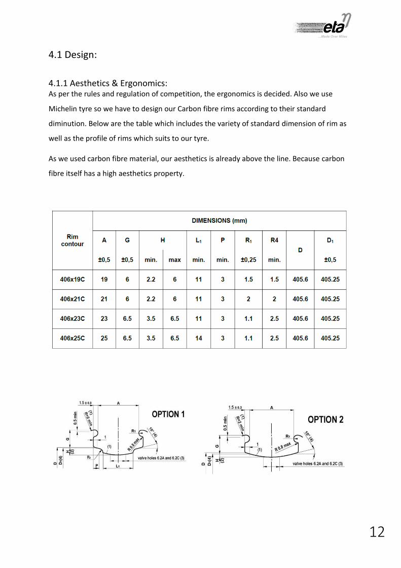
4.1.1 Aesthetics & Ergonomics: As per the rules and regulation of competition, the ergonomics is decided. Also we use
Michelin tyre so we have to design our Carbon fibre rims according to their standard
diminution. Below are the table which includes the variety of standard dimension of rim as
well as the profile of rims which suits to our tyre.
As we used carbon fibre material, our aesthetics is already above the line. Because carbon
fibre itself has a high aesthetics property.

13
4.1.2 Hub Design: A hub is the centre part of a bicycle wheel. It consists of an axle, bearings and a hub shell.
The hub shell typically has two machined metal flanges to which Carbon fibre disc can be
attached. Hub shells can be one-piece with press-in cartridge or free bearings or, in the case
of older designs; the flanges may be affixed to a separate hub shell. The design of hub for
this year is as shown in figure

14
4.1.3 Mould Design:
As mould is very important part to manufacture carbon fibre rims. If mould is not proper in
shape than finally the output, i.e. disc is not gets properly moulded. So in order to eliminate
any error during the carbon fibre layup process, we decided to make our mould from
Aluminium material.
To make Al mould we first design the exact wooden pattern and after that we perform sad
casting process for making aluminium mould. The design of mould is as shown in figure.
15
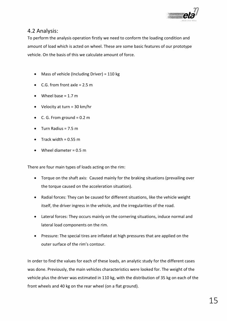
4.2 Analysis: To perform the analysis operation firstly we need to conform the loading condition and
amount of load which is acted on wheel. These are some basic features of our prototype
vehicle. On the basis of this we calculate amount of force.
Mass of vehicle (Including Driver) = 110 kg
C.G. from front axle = 2.5 m
Wheel base = 1.7 m
Velocity at turn = 30 km/hr
C. G. From ground = 0.2 m
Turn Radius = 7.5 m
Track width = 0.55 m
Wheel diameter = 0.5 m
There are four main types of loads acting on the rim:
Torque on the shaft axis: Caused mainly for the braking situations (prevailing over
the torque caused on the acceleration situation).
Radial forces: They can be caused for different situations, like the vehicle weight
itself, the driver ingress in the vehicle, and the irregularities of the road.
Lateral forces: They occurs mainly on the cornering situations, induce normal and
lateral load components on the rim.
Pressure: The special tires are inflated at high pressures that are applied on the
outer surface of the rim’s contour.
In order to find the values for each of these loads, an analytic study for the different cases
was done. Previously, the main vehicles characteristics were looked for. The weight of the
vehicle plus the driver was estimated in 110 kg, with the distribution of 35 kg on each of the
front wheels and 40 kg on the rear wheel (on a flat ground).

16
Type of load Value with safety factor Units
Radial Force 400 N
Lateral Force 750 N
Brake Force 350 N
Air pressure 5.5 Bar
Torque 40 N-m

17
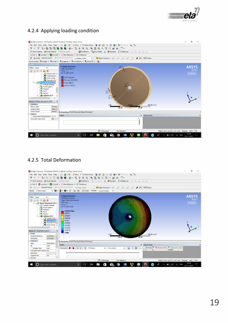
The finite element method (FEM) is a numerical procedure for obtaining solutions to the
Differential equations that describe, or approximately describe a wide variety of physical
problems like solid mechanics, electromagnetism, fluid dynamics, heat transfer inter alia.
After completing our design phase we used to do analysis of Carbon fibre disc in ANSYS ACP
18.0 and aluminium hub in ANSYS 18.0. These are some pictures which explain the result of
analysis.
4.2.1 Mesh View

18
4.2.2 Total Shear Stress
4.2.3 Total Deformation
19
4.2.4 Applying loading condition
4.2.5 Total Deformation

20
4.2.6 Applying air pressure
4.2.7 Meshing of Disc

21
4.2.8 Ansys Composite Processor (ACP)

22
4.3 Manufacturing:
In this phase we convert out design into actual product and after this stage, we are going to
test that component. Below steps shows gradual making of Carbon Fibre Rims.
4.3.1 MDF Pattern
In order to make the Aluminum mould via sand casting process, firstly we have to prepare
wooden pattern made up from MDF material. This design of pattern includes all the casting
allowances like shrinkage, machining allowance etc. We have completed this stage and
these are some pictures of MDF pattern. This is done on 3 axis CNC router machine.
4.3.2 Aluminum mould using Sand Casting process
After making the wooden pattern, we use this pattern to make aluminum casted mould. The
picture shows the aluminum mould. The process used to make aluminum mould is Sand
casting procress.

23
4.3.4 Machining of Casted mould for finishing cut on VMC After the process of casting, the surface of casted mould is rough and irregular. So in order
ot get good surface finish, we will perform machining operation on aluminum mould. And
after machining we will perform buffing operation in order to get mirror finish on mould.
(We cannot able to put image, because we are currently working on this stage)
4.3.5 Manufacturing of CF Disc from mould After perfect mould making process, we shift our focus towards manufacturing of carbon
fibre disc. According to analysis, we decided to stack the carbon fibre as follows
Rim Area Disc Area
Layer No. GSM Orientation Layer No. GSM Orientation
1 250 0 1 250 0
2 250 45 2 250 45
3 250 90 3 250 90
4 250 -45 4 (Core Material) NA 0
5 250 0 5 250 -45
6 250 45 6 250 90
7 250 90 7 250 -45
8 250 -45 8 250 0
9 250 0
Total thickness of Rim area is 3 mm and disc is
approximately 2.25 mm.
10 250 45
11 250 90
12 250 -45
13 250 0
24
4.3.6 Hub machining on CNC Lathe Hub is main part of wheel of any vehicle. In order to match our carbon fibre disc with hub,
we design new hub which is lighter in weight as compare to previous hub.
To manufacture hub we already purchase the aluminum round bar of 80 mm diameter and
1000 mm in length. We will do machining on CNC Lathe.
4.3.7 Assembly of Disc and Hub using Loctite as bonding agent After the manufacturing of both Hub and Disc, we will assemble both components together
by means of Loctite. Loctite is the best option available to stick aluminum with any
composite material part.
4.4 Testing
After the manufacturing phase gets completed, we shift our focus on testing of our wheel.
We will do two types of testing on wheel. One is Idle testing and other is on road testing.
Idle testing is done when the wheel is not connected to the vehicle. Is is also called off load
testing. In Idle testing, we will apply load to wheel is all the direction and rotate at required
speed.
In case of on road testing the weight of driver as well as breaking force is acting on wheel.
So in order to check weather our wheel is sustain that high breaking force or not, we do on
road testing. It is also called as on Load testing, where actually all the loads are acting on
Carbon fibre wheel.

25
CHAPTER - 5
EXPECTED CONCLUSION
Description Expected
(A18)
Previous
(Triton) Conclusion
Bearing Hybrid ceramic
bearing Steel Bearing
Very minor
Frictional loss
Hub Simple is construction Complicate in
construction
Easy to
manufacture
Hub weight 140 grams 330 grams 42% weight
reduction
Disc material Carbon Fibre Aluminium spokes Great aesthetics
and aerodynamics
Rim construction Integral part of disc Different from spokes Easy to
manufacture
Tyre neoprene rubber tyre Michelin tyre Low rolling
resistance
CHAPTER - 6
FUTURE SCOPE
Nowadays people demanding for product of low weight and good in strength. This project is
aims toward that demand only. The project has provided theoretical baggage in relation
with structural parts made of composite materials, particularly with carbon fibre reinforced
polymers. In other parts of the Team ETA’s vehicle a weight reduction can also be achieved
using composites, a good option would be the chassis of the vehicle. Before that some more
experience is needed and the manufacturing of the rims could be an appropriate start. In
relation with the rims designed in this project, few points should be reviewed before the
fabrication of these. On one hand the manufacturing process must be studied further. The

26
type of epoxy used and the curing conditions have to be known. The tooling needed for the
manufacturing process has to be custom for the rim, which is basically the moulds and some
tools for the assembly process. If the budget and the time allow it, building a first prototype
for the rim would be a good option. It would provide experience on the manufacturing
process and also a verification of the design, as well the real weight reduction. On the other
hand the hub’s design needs to fit into the whole design. The current aluminum hub could
be optimized to reduce its weight or otherwise the design of the hub made of carbon fibre
reinforced polymer could be studied since it can provide a better overall weight reduction
for the rims. For this last option, the present project can provide useful information.
CHAPTER - 7
BIBLIOGRAPHY
Lin, J., Jin, Y., Zhang, Z., Cui, X., 2014. Strength analysis of the Carbon-Fibre Reinforced Polymer Impeller Based on Fluid Solid Coupling Method. In: Mathematical problems in Engineering. Hindawi Publishing Corporation. Vol. 2014. Article ID 803261.
W.V. Chaves, E., 2013. Notes on Continuum Mechanics. Barcelona, Spain: International Center for Numerical Methods in Engineering (CIMNE).
McGinty, B., 2014. Finite Deformation Continuum Mechanics with emphasis on metals & incompressible materials. [Online] Available at: http://www.continuummechanics.org
Ferrer, M., 2014. Continuum mechanics (ETSEIB-UPC). (in Catalan) [Online] Available at: http://mmc.etseib.upc.edu
Gay, D. & Hoa, S. V., 2007. Composite Materials, Interest, and Properties. In: Composite Materials: Design and Applications, 2nd ed. Boca Raton, FL: Taylor&Francis Group.
Gay, D. & Hoa, S. V., 2007. Ply Properties. In: Composite Materials: Design and Applications, 2nd ed. Boca Raton, FL: Taylor&Francis Group.
Hull, D. & Clyne, T.W., 1996. An introduction to Composite Materials (Cambridge solid state science series), 2nd ed. Cambridge, United Kingdom: Cambridge University Press.
27
ACKNOWLEDGEMENT
This report is the result of my bachelor project that was carried out in the K. J. Somaiya
College of Engineering, in Mumbai, during the Academic year 2017-18.
I would like to thank the people of the Team ETA who helped me in any way, especially
Sandeep Chopade sir and Luckman sir.
I would like to extend my appreciations to my supervisor, Vijay Khaparde sir and my
examiner A. K. Gangrade sir, for their guidance during the project.
Finally, I would also like to thank my family and especially my parents and my lord.