design analysis of a hydrostatic thrust pad using cfd … icriet-220.pdf · is to analyze the flow...
TRANSCRIPT
International Journal on Emerging Technologies (Special Issue on ICRIET-2016) 7(2): 237-243(2016)
ISSN No. (Print) : 0975-8364
ISSN No. (Online) : 2249-3255
“Design Analysis of a Hydrostatic Thrust Pad using CFD Approach”
Prof. Rajkumar Panchal* and Prof . M. Rajashekar** *Professor, IOK College of Engineering PUNE, INDIA
** Professor, BKIT, BHALKI, INDIA
(Corresponding author: Prof. Rajkumar Panchal)
(Received 28 September, 2016 Accepted 29 October, 2016)
(Published by Research Trend, Website: www.researchtrend.net)
ABSTRACT: The distribution of pressure in the film of liquid between hydrostatic pad and the surface on
which it slides is not uniform. In analytical approach of designing, the pressure distribution is assumed
constant in pocket and varies linearly in the land. Practically there is logarithmic pressure drop from inner
edge of the land to the outer edge of the land. And other limitation is that, many coefficients are required for
evaluating rate of flow of liquid. As such, a new numerical method using CFD approach is developed in the
present dissertation for computing all the characteristics of a hydrostatic thrust pad. Using this CFD approach, these coefficients are not required for analyzing the rate of flow of liquid. The object of this project
is to analyze the flow of fluid by modelling the fluid region between hydrostatic pad and the surface on which
it slides. CFD module “FLOTRON” of ANSYS analysis package has been used for carrying out the analysis.
Keywords: Hydrostatic, Vibration, CFD, FLOTRON.
I. INTRODUCTION
This paper presents a study concerning the Plane
bearing(slide way bearing) are restricted to application
where load on the pad is always directed towards the
slide way, their principal use to date has been for
supporting heavy loads moving at no more than moderate
speeds. However, a application involving comparatively high speeds are to be found in planing, grinding
machines with quick return motion but, in the main
inertia forces set lower limits for translatory speeds than
for rotary speeds. A large component such as the rotary
table of a vertical boring mill or the reflector of a large
astronomical telescope may be mounted on a ring of
hydrostatic pads on a circular track as a number of
separate hydrostatic pads on sliding on a plane slide way.
There are three Basic Types of Guide way Systems
used in Machine Tools The oldest, the plain sliding way, was built in both a
dovetail and a square edge style, with the square edge or “box” way being predominant. The advantage of box
ways was simple design and high rigidity, but the
disadvantage was high friction, stick-slip, wear, and
limited speed capability. In the late ‘60’s and early 70’s,
Teflon-impregnated sheet-type materials such as Turcite
and Rulon became available, and were applied as way
liners, which reduced the friction and the stick-slip of
plain box ways. However, speed is still limited and wear
is inevitable. But, feed rates were improved over plain
ways and positioning and profiling accuracy was
improved due to reduction of stick-slip.
To attain even higher speeds and eliminate wear, rolling
element way systems were developed, in which hardened
ball or cylindrical roller bearings carried the load and
greatly reduced friction and eliminated stick slip. The
introduction of antifriction rolling element way systems,
or “linear ways”, utilizing either recirculating ball or
roller bearings in a “truck” assembly, traveling on a linear guiderail, made machine construction easier as
they were sold as pre-assembled units which could easily
be bolted on to machine structures. The disadvantage of
linear ways, however, is that, due to the relatively small
load-bearing contact area, particularly with ball-type
rollers, they unfortunately have very low dynamic
stiffness. To improve it, most systems utilize opposed
sets of bearings which are preloaded against each other.
This helps a little, but still does not match that of box
ways. It is dynamic stiffness that resists shock, chatter
and vibration, and improves surface finish and tool life.
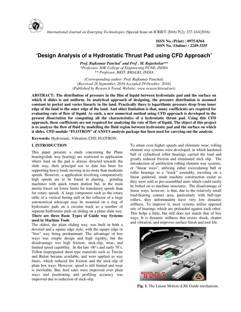
Fig. 1. The Linear Motion (LM) Guide mechanism.
et
Panchal and Rajashekar 238
Stout-KJ; Tawfik-M; Pink-EG [1]: In the year 1978 has
prepared useful design charts and procedure to assist in
designing both journal and thrust bearing. In addition to
that general guidelines are given for material selection,
bearing geometry and system design. Padate-JC;
Samanth-LN; Samasundram-S [2]: In the year 1976
presented a study of hydrostatic and aerostatic slide way bearing by numerical methods. Jayachandra-Prabhu-T;
Ganeshan-N [10]: In the year Dec 1984 described the
finite element analysis and experimental study of circular
recess hydrostatic thrust bearing. Braun,MJ; Dzodzo-M
[14]: In the year 1995 describes on a study of the pocket
depth on the flow patterns and pressure magnitudes in a
hydrostatic bearing pocket, the development of the
pressure is analyzed both along the transversal and in the
depth of the pocket and restrictor. Galerkin finite
element method using linear triangular element has been
developed to solve the Reynolds equation including the rotational lubricant inertia term in polar coordinate
system. The method has been applied to study plane
hydrostatic bearing with four circular recesses.
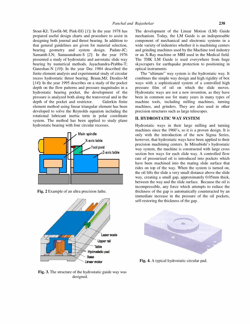
Fig. 2 Example of an ultra precision lathe.
Fig. 3. The structure of the hydrostatic guide way was
designed.
The development of the Linear Motion (LM) Guide
mechanism. Today, the LM Guide is an indispensable
component of mechanical and electronic systems in a
wide variety of industries whether it is machining centers
and grinding machines used by the Machine tool industry
or an X-Ray machine or MRI used in the Medical field.
The THK LM Guide is used everywhere from huge skyscrapers for earthquake protection to positioning in
optical instruments
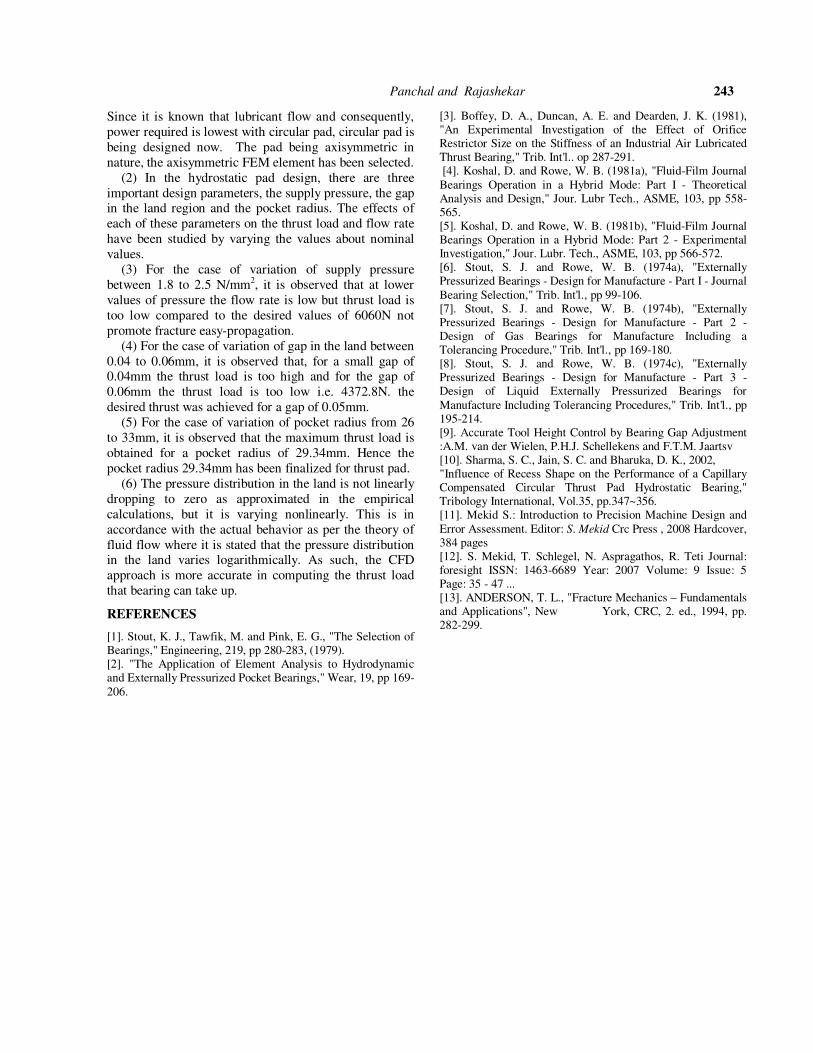
The “ultimate” way system is the hydrostatic way. It
combines the simple way design and high rigidity of box
ways with a sophisticated system of a controlled high
pressure film of oil on which the slide moves.
Hydrostatic ways are not a new invention, as they have
been in common use for many years in many types of
machine tools, including milling machines, turning
machines, and grinders. They are also used in other
precision structures such as large telescopes.
II. HYDROSTATIC WAY SYSTEM
Hydrostatic ways in their large milling and turning
machines since the 1960’s, so it is a proven design. It is
only with the introduction of the new Sigma Series,
however, that hydrostatic ways have been applied to their
precision machining centers. In Mitsubishi’s hydrostatic
way system, the machine is constructed with large cross
section box ways for each slide way. A controlled flow
rate of pressurized oil is introduced into pockets which
have been machined into the mating slide surface that
rides on top of the way. When the system is turned on,
the oil lifts the slide a very small distance above the slide way, creating a small gap, approximately 0.05mm thick,
between the way and the slide surface. Because the oil is
incompressible, any force which attempts to reduce the
thickness of the gap is automatically counteracted by an
immediate increase in the pressure of the oil pockets,
self-restoring the thickness of the gap.
Fig. 4. A typical hydrostatic circular pad.

Panchal and Rajashekar 239
Fig. 5. A typical hydrostatic rectangular pad.
Hydrostatic pads may be of any shape in plane
rectangular or circular as shown in Figure 4 and Figure 5
The lowest values of lubricant flow and pumping power
for an individual pad are achieved with circular pads.
If certain assumption are made it is not difficult to calculate, with fair degree of precision, the operating
characteristics of liquid –lubricated hydrostatic pad
working at low or moderate speeds when all particulars
of the design, including the physical properties and
supply of pressure of the liquid, are decided.
The assumption are a) The liquid may be considered
completely incompressible . b) The faces of the land and
slide way are strictly parallel. c) The height of the
inevitable surface irregularities is negligible compared
with normal working clearance. d) If capillary inflow
restrictor is used the flow in it is purely laminar. e) the flow in the gap between the land and sideways is purely
laminar. f) the viscosity of the liquid does not change
significantly between entry to the inflow restrictor and
exit from the working gap. g) The relative sliding speed
is too low. h) The depth of pocket is large compared with
normal working clearance say not less than 20 times
clearance. i) The bearing operates on the constant supply
system. j) End effects at entry to and exit form the inflow
restrictor and the out can be neglected.
Fig. 6. The slide is supported and guided by these thin
films of pressurized oil.
III. ANALYSIS RESULTS AND DISCUSSION
Virtual bearing area (A) Figures shows the some important parameters of a
hydrostatic circular thrust pad. Here ‘D’ is the outside
diameter and‘d’ inside diameter of the land region P2 is
the pressure distribution in the thrust pad. It can be seen from the fig. that pressure is constant in the pocket and it
decrease to zero at the end. The oil enters into the pocket
to that small central orifice and it flows out radially
across the pocket and the land.
Fig. 7. Actual pressure distribution.
The ANSYS FLOTRAN elements, FLUID141 and
FLUIDI42, used to solve for 2-D and 3-D flow, pressure,
and temperature distributions in a single phase viscous
fluid. For these elements, the ANSYS program calculates
velocity components, pressure, and temperature from the
conservation of three properties: mass, momentum, and
energy.
Table 1: FLOTRAN Elements.

Panchal and Rajashekar 240
Fig. 8. Assumed pressure distribution.
The annular gap between the land and the slide way
constitutes a divergent passage the cross sectional area of
which increases steadily from ‘лdh’ at inlet to ‘лDh’ at
outlet.
Since the fluid is virtually incompressible and therefore
the volumetric flow ‘Q’ is the same at all sections along
the passage i.e. at all radii-the flow velocity must
decrease steadily from inlet at the inner edge of the land
to outlet at its outlet edge. The flow velocity at any radius is dependent on the
pressure gradient at this radius and it can be shown that
the radial distribution of pressure required to produce the
steadily decreasing flow velocity inherent in the constant
volumetric flow is a logarithmic relation between fluid
pressure and radius across the face of the land. The
resulting thrust between the land and the slide way is
given by.
� = � �P� π����� ������ �⁄
�−d�� ……… (1)
V. CASE 1: STUDY OF THRUST FORCE AND
FLOW RATE WHEN SUPPLY PRESSURE IS
VARIED
GAP in the land, h= 0.05mm, Pocket radius,
Ro=29.34mm, R1=58.68mm, Orifice diameter= 0.72mm,
length of the resistor= 87.15mm, Dynamic viscosity of
oil= 8.7x 10⁻⁷ NS/mm2, density of oil = 8x 10⁻⁷ kg/mm3
For Pressure 1.8 N/mm2:
Fig. 9. Geometric model of the region.
Figure 5 shows the geometric model of the region i.e.
model since the geometry as well as loads and boundary
conditions are axisymmetric, it is sufficient to model
axisymmetric portion.
Fig. 10. 3-D Geometric model of the region.
Fig. 11. Finite Element Method (FEM) model of the
thrust pad.
Fig.12. The zoomed up portion of the mesh in the
pocket region.
VI. THE BOUNDARY CONDITION APPLIED IN
THE MODEL
Application of loads and boundary conditions is the very
important aspect also a difficult task for a designer. For
this a through understanding of the problem is necessary.
The boundary conditions are defined for outer surface
Vx=0, Vy= 0 and normal velocity component Vx=0 to its
axis of symmetry and supply pressure (Ps) is defined at
the inlet cylinder surface is 2.25 N/mm2 and Outlet
pressure as 0,figures 9 & 10 shows the Boundary
Condition Applied in the Model.

Panchal and Rajashekar 241
Fig.13. Boundary Condition Applied in the Model
Fig.14. Boundary Condition Applied in the Model.
Velocity, Vx = 0 on the line AB.
Velocity, Vy =0 on the line AC.
Velocity, Vx =0, Vy =0, along the lines CD, DE, EF, FG, GH.
Pressure at the outlet, P = 0 (exposed to atmospheric
pressure).
Fig. 15. Pressure acting on the slide Vs pocket radius.
Table 1 shows the Pressure acting on the slide Vs Pocket
Radius. The table also shows the thrust load acting on the
slide and cumulative thrust due to this pad.
Radius, mm Pressure, N/sqmm
Force, N
0 0.961
24.231
2.934 0.831
2224.878
29.34 0.831
438.720
32.274 0.714
411.771
35.208 0.610
380.305
38.142 0.515
343.552
41.076 0.426
301.945
44.010 0.344
256.119
46.944 0.267
205.709
49.878 0.194
151.446
52.812 0.126
93.708
55.746 0.0613
32.326
58.68 0
Cumulative Force 4864.71
The procedure for computing the thrust force is given
below.
Force, F = π (Ri2 – Rj
2) * (Pi + Pj)/2
F1= π (2.9342 – 0.0002) * (0.961+0.831)/2 = 24.231N
F2= π (29.3402 – 2.9342) * (0.831) =
2224.878N
F3= π (32.2742 – 29.3402) * (0.714+0.831)/2 =
438.720N
F4= π (35.2082 – 32.2742) * (0.714+0.610)/2 =
411.771N
F5= π (38.1422 – 35.2082) * (0.515+0.610)/2 =
380.305N
F6= π (41.0762 – 38.1422) * (0.515+0.426)/2 =
343.552N F7= π (44.0102 – 41.0762) * (0.344+0.426)/2 =
301.945N
F8= π (46.9442 – 44.0102) * (0.344+0.267)/2 =
256.119N
F9= π (49.8782 – 46.9442) * (0.194+0.267)/2 =
205.709N

Panchal and Rajashekar 242
F10= π (52.8122 – 49.8782) * (0.194+0.126)/2 =
151.446N
F11= π (55.7462 – 52.8122) * (0.0613+0.126)/2 =
93.708N
F12= π (58.682 – 55.7462) * (0.0613+0.0)/2 = 32.326N
Cumulative Force, Ftotal = 4864.71 N
Cumulative Force, Ftotal = F1+ F2+F3+F4+F5+F6+F7+F8+F9+
F10+F11+F12.
Fig. 16. Velocity profile of the fluid in the restrictor.
Fig. 17. Vector plot of velocity of the fluid in the
restrictor.
Table shows the velocity profile in the restrictor vs
Radius of the restrictor. From this Discharge through the
thrust pad is computed.. The procedure for computing the discharge is
described below.
Velocity,
V=425.68+418.74+411.78+404.81+394.84+381.58+3
65.32+349.06+332.80+316.55+290.07+263.59+237.11+
210.63+184.15+147.32+110.49+36.831+0
= 5284.381mm/sec
= 5284.381*2 = 10568.762
= 10568.762 + 432.680 = 11001.442mm/sec Vtotal = 11001.442mm/sec
Vavg = 11001.442 / 41= 268.328 mm/sec
Area = πr2 = π (0.36)2 = 0.4071 mm2
Flow rate, q = Area * Vavg
= 0.4071 * 268.328
q = 109.236 mm3/sec
Fig. 18. Flow through the Bearing Vs Supply pressure.
Fig. 19. Thrust force Vs Supply pressure.
CONCLUSIONS
(1) Hydrostatic pads are used in slide ways to take
very high loads and with medium to low sliding velocity.
FLOTRAN CFD analysis software has been used in the
dissertation for analyzing the hydrostatic thrust pad. The working load being resisted by the pad is 6060N.
Panchal and Rajashekar 243
Since it is known that lubricant flow and consequently,
power required is lowest with circular pad, circular pad is
being designed now. The pad being axisymmetric in
nature, the axisymmetric FEM element has been selected.
(2) In the hydrostatic pad design, there are three
important design parameters, the supply pressure, the gap in the land region and the pocket radius. The effects of
each of these parameters on the thrust load and flow rate
have been studied by varying the values about nominal
values.
(3) For the case of variation of supply pressure
between 1.8 to 2.5 N/mm2, it is observed that at lower
values of pressure the flow rate is low but thrust load is
too low compared to the desired values of 6060N not
promote fracture easy-propagation.
(4) For the case of variation of gap in the land between
0.04 to 0.06mm, it is observed that, for a small gap of 0.04mm the thrust load is too high and for the gap of
0.06mm the thrust load is too low i.e. 4372.8N. the
desired thrust was achieved for a gap of 0.05mm.
(5) For the case of variation of pocket radius from 26
to 33mm, it is observed that the maximum thrust load is
obtained for a pocket radius of 29.34mm. Hence the
pocket radius 29.34mm has been finalized for thrust pad.
(6) The pressure distribution in the land is not linearly
dropping to zero as approximated in the empirical
calculations, but it is varying nonlinearly. This is in
accordance with the actual behavior as per the theory of
fluid flow where it is stated that the pressure distribution in the land varies logarithmically. As such, the CFD
approach is more accurate in computing the thrust load
that bearing can take up.
REFERENCES
[1]. Stout, K. J., Tawfik, M. and Pink, E. G., "The Selection of Bearings," Engineering, 219, pp 280-283, (1979). [2]. "The Application of Element Analysis to Hydrodynamic and Externally Pressurized Pocket Bearings," Wear, 19, pp 169-
206.
[3]. Boffey, D. A., Duncan, A. E. and Dearden, J. K. (1981), "An Experimental Investigation of the Effect of Orifice Restrictor Size on the Stiffness of an Industrial Air Lubricated Thrust Bearing," Trib. Int'l.. op 287-291. [4]. Koshal, D. and Rowe, W. B. (1981a), "Fluid-Film Journal
Bearings Operation in a Hybrid Mode: Part I - Theoretical Analysis and Design," Jour. Lubr Tech., ASME, 103, pp 558-565. [5]. Koshal, D. and Rowe, W. B. (1981b), "Fluid-Film Journal Bearings Operation in a Hybrid Mode: Part 2 - Experimental Investigation," Jour. Lubr. Tech., ASME, 103, pp 566-572. [6]. Stout, S. J. and Rowe, W. B. (1974a), "Externally Pressurized Bearings - Design for Manufacture - Part I - Journal
Bearing Selection," Trib. Int'l., pp 99-106. [7]. Stout, S. J. and Rowe, W. B. (1974b), "Externally Pressurized Bearings - Design for Manufacture - Part 2 - Design of Gas Bearings for Manufacture Including a Tolerancing Procedure," Trib. Int'l., pp 169-180. [8]. Stout, S. J. and Rowe, W. B. (1974c), "Externally Pressurized Bearings - Design for Manufacture - Part 3 - Design of Liquid Externally Pressurized Bearings for
Manufacture Including Tolerancing Procedures," Trib. Int'l., pp 195-214. [9]. Accurate Tool Height Control by Bearing Gap Adjustment :A.M. van der Wielen, P.H.J. Schellekens and F.T.M. Jaartsv [10]. Sharma, S. C., Jain, S. C. and Bharuka, D. K., 2002, "Influence of Recess Shape on the Performance of a Capillary Compensated Circular Thrust Pad Hydrostatic Bearing," Tribology International, Vol.35, pp.347~356. [11]. Mekid S.: Introduction to Precision Machine Design and
Error Assessment. Editor: S. Mekid Crc Press , 2008 Hardcover, 384 pages [12]. S. Mekid, T. Schlegel, N. Aspragathos, R. Teti Journal: foresight ISSN: 1463-6689 Year: 2007 Volume: 9 Issue: 5 Page: 35 - 47 ... [13]. ANDERSON, T. L., "Fracture Mechanics – Fundamentals and Applications", New York, CRC, 2. ed., 1994, pp. 282-299.