design and analysis of a hyperspectral microwave receiver
TRANSCRIPT

W. Blackwell, C. Galbraith, T. Hancock, R. Leslie, I. Osaretin, M. Shields, P. Racette (NASA GSFC), L. Hilliard (NASA GSFC)
IGARSS 2012
Design and Analysis of a Hyperspectral Microwave Receiver Subsystem

IGARSS - 2 WJB 7/25/12
• Project summary, key objectives, and roles/responsibilities • RF receiver electronics and scan head • IF processor module • Next steps
Outline
IGARSS - 3 WJB 7/25/12
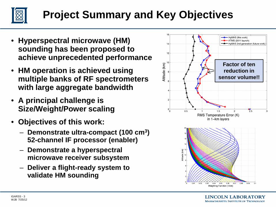
• Hyperspectral microwave (HM) sounding has been proposed to achieve unprecedented performance
• HM operation is achieved using multiple banks of RF spectrometers with large aggregate bandwidth
• A principal challenge is Size/Weight/Power scaling
• Objectives of this work: – Demonstrate ultra-compact (100 cm3)
52-channel IF processor (enabler) – Demonstrate a hyperspectral
microwave receiver subsystem – Deliver a flight-ready system to
validate HM sounding
Project Summary and Key Objectives
Factor of ten reduction in
sensor volume!!

IGARSS - 4 WJB 7/25/12
HyMAS System Components Roles and Responsibilities
Scan Head Assembly (GSFC CoSMIR/CoSSIR)

IGARSS - 5 WJB 7/25/12
HyMAS (9-channel) IF Frequency Plan

IGARSS - 6 WJB 7/25/12
• K-connector (18-29 GHz) input from RF front-end • Two IF amplifiers (18-29 GHz)
– Buffered with attenuators for gain adjustment and matching at IF input/output • Provides termination for RF front-end output and multiplexer input • Nominally 3 dB at input/output, “0 dB” in between stages
• Multiplexer channelizes IF band • Detectors detect power at output of each channel • Op-amp fed by detectors, drives ADC • Microcontroller sequences data flow
IF Processor Description

IGARSS - 7 WJB 7/25/12
HyMAS – IF Processor

IGARSS - 8 WJB 7/25/12
• Single port feeds 9-channels through a corporate feed power splitting network – Reduces interaction among contiguous channels – Low-risk for initial demonstration
• IF channel filters are LTCC-based substrate integrated waveguide (SIW) cavity types – High unloaded Q resonators (500+) in small volume for low insertion
loss and sharp filter skirts – Probe/bond pads for S-parameter testing and assembly
• First 9-channel design completed and in fabrication – Omega Micro Technology (DuPont 9K7), expect parts in 9/2012
IF Multiplexer

IGARSS - 9 WJB 7/25/12
• Substrate Integrated Waveguide (SIW) filters offer lower insertion loss and better filter shape factor than stripline interdigital filters due to their higher Q (> 500) resonators – Filters are realized in two-layer LTCC stack with via “fences”
creating the waveguide side walls – Via “posts” control coupling in between resonator cavities
HyMAS LTCC SIW Filters
21.00 22.00 23.00 24.00 25.00Freq [GHz]
-80.00
-70.00
-60.00
-50.00
-40.00
-30.00
-20.00
-10.00
0.00
Y1
SIW resonatorXY Plot 1 ANSOFT
Curve InfodB(S(Port1,Port1))
Setup1 : Sw eep1dB(S(Port2,Port1))
Setup1 : Sw eep1
HFSS Simulation HFSS Model
WG cavity
Coupling (“iris”)

IGARSS - 10 WJB 7/25/12
IF Channel 1 (HFSS)
18 20 22 24 26 2816 30
-80
-60
-40
-20
-100
0
freq, GHz
dB(S
(2,1
))dB
(S(1
,1))
Out of band response to be attenuated by detector roll-off

IGARSS - 11 WJB 7/25/12
IF Channel 2 (HFSS)
24 25 26 27 28 2923 30
-120
-100
-80
-60
-40
-20
-140
0
-25
-20
-15
-10
-5
-30
0
freq, GHz
dB(S
(2,1
))m1 m2dB
(S(1,1))
m1freq=dB(S(2,1))=-6.218
23.96GHz
m2freq=dB(S(2,1))=-6.059
24.50GHz

IGARSS - 12 WJB 7/25/12
IF Channel 3 (HFSS)
24 25 26 27 28 2923 30
-120
-100
-80
-60
-40
-20
-140
0
-30
-20
-10
-40
0
freq, GHz
dB(S
(2,1
))
m1
m2dB
(S(1,1))
m1freq=dB(S(2,1))=-6.197
24.57GHz
m2freq=dB(S(2,1))=-5.964
25.13GHz

IGARSS - 13 WJB 7/25/12
IF Channel 4 (HFSS)
24 25 26 27 28 2923 30
-120
-100
-80
-60
-40
-20
-140
0
-30
-25
-20
-15
-10
-5
-35
0
freq, GHz
dB(S
(2,1
))
m1
m2dB
(S(1,1))
m1freq=dB(S(2,1))=-5.757
25.16GHz
m2freq=dB(S(2,1))=-6.092
25.79GHz

IGARSS - 14 WJB 7/25/12
IF Channel 5 (HFSS)
24 25 26 27 28 2923 30
-140
-120
-100
-80
-60
-40
-20
-160
0
-30
-20
-10
-40
0
freq, GHz
dB(S
(2,1
))
m1
m2dB
(S(1,1))
m1freq=dB(S(2,1))=-6.070
25.79GHz
m2freq=dB(S(2,1))=-6.051
26.42GHz
IGARSS - 15 WJB 7/25/12
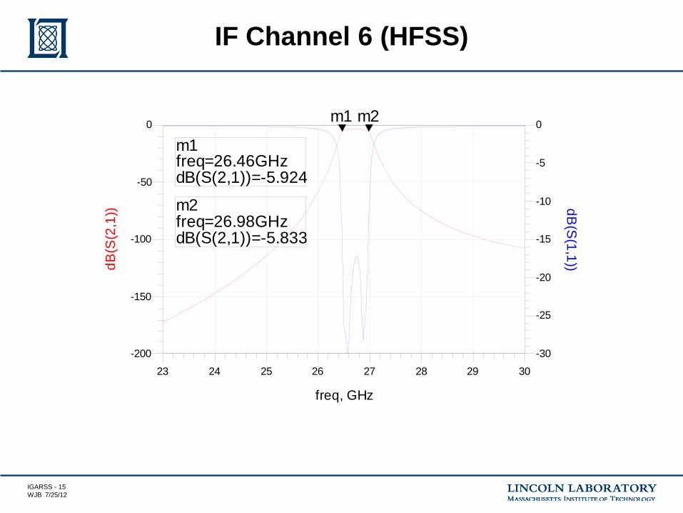
IF Channel 6 (HFSS)
24 25 26 27 28 2923 30
-150
-100
-50
-200
0
-25
-20
-15
-10
-5
-30
0
freq, GHz
dB(S
(2,1
))
m1
m2dB
(S(1,1))
m1freq=dB(S(2,1))=-5.924
26.46GHz
m2freq=dB(S(2,1))=-5.833
26.98GHz

IGARSS - 16 WJB 7/25/12
IF Channel 7 (HFSS)
24 25 26 27 28 2923 30
-150
-100
-50
-200
0
-25
-20
-15
-10
-5
-30
0
freq, GHz
dB(S
(2,1
))
m1
m2dB
(S(1,1))
m1freq=dB(S(2,1))=-5.974
27.04GHz
m2freq=dB(S(2,1))=-5.876
27.65GHz

IGARSS - 17 WJB 7/25/12
IF Channel 8 (HFSS)
24 25 26 27 28 2923 30
-150
-100
-50
-200
0
-25
-20
-15
-10
-5
-30
0
freq, GHz
dB(S
(2,1
))
m1
m2dB
(S(1,1))
m1freq=dB(S(2,1))=-5.739
27.68GHz
m2freq=dB(S(2,1))=-5.522
28.24GHz

IGARSS - 18 WJB 7/25/12
IF Channel 9 (HFSS)
24 25 26 27 28 2923 30
-200
-150
-100
-50
-250
0
-25
-20
-15
-10
-5
-30
0
freq, GHz
dB(S
(2,1
))
m1
m2dB
(S(1,1))
m1freq=dB(S(2,1))=-6.070
28.33GHz
m2freq=dB(S(2,1))=-6.134
28.86GHz

IGARSS - 19 WJB 7/25/12
IF Filter Layout (LTCC)
30 mm
8 m
m
4.5 mm

IGARSS - 20 WJB 7/25/12
IF Processor Form Factor 1 Horizontal Resonators
Top View: 8/9-channel Panel Side View: 52-ch IF Processor

IGARSS - 21 WJB 7/25/12
IF Processor Form Factor 2 Horizontal+Vertical (Stacked) Resonators
Top View: 26-channel Panel Side View: 52-ch IF Processor
IGARSS - 22 WJB 7/25/12
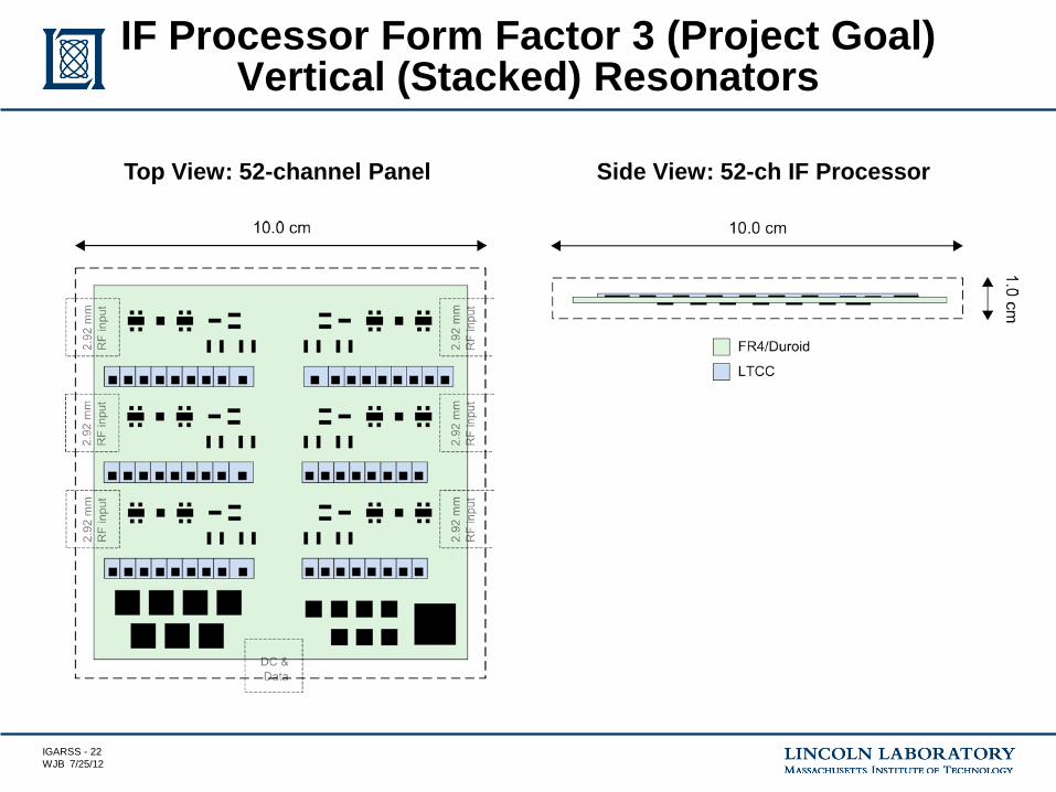
IF Processor Form Factor 3 (Project Goal) Vertical (Stacked) Resonators
Top View: 52-channel Panel Side View: 52-ch IF Processor

IGARSS - 23 WJB 7/25/12
• Hyperspectral microwave sensors could change the landscape of atmospheric sounding for both LEO and GEO systems.
• An intermediate frequency processor fabricated in LTCC technology is a key innovation enabling ultracompact microwave radiometry in a variety of applications with severe constraints on size, weight, and power.
• Fabrication and testing of the hyperspectral microwave receiver subsystem will occur in 2012/2013 with airborne validation in 2014/2015.
Summary

IGARSS - 24 WJB 7/25/12
Backup

IGARSS - 25 WJB 7/25/12
CoSMIR/CoSSIR Scan Head

IGARSS - 26 WJB 7/25/12
Frequency Plan