design and analysis of connecting rod using composite ... · design and analysis of connecting rod...
TRANSCRIPT

DESIGN AND ANALYSIS OF CONNECTING
ROD USING COMPOSITE MATERIALS
(Al6061-15% B4C-1.5% SiC) J. Manikandan
#Assistant Professor, Department of Mechanical Engineering, University College of Engineering (A Constituent College of Anna
University, Chennai )
Abstract— The Connecting rod is the intermediate member between the piston and crankshaft. It converting the reciprocating motion
of the piston to rotary motion of the crank. Also it faces a lot of tensile & compressive loads during its lifetime and also it withstand
more temperature during its operation. Generally connecting rod is manufactured using carbon steel. In applications, aluminum
alloys are mostly used. In this work, the existing connecting rod (Aluminium360) can be replaced by new composite materials (i.e.
aluminum based composite material reinforced with Boron carbide & Silicon carbide). Pro-e software is used to generate the 3-D
model of connecting rod & ANSYS is used to analyze the connecting rod.
Keywords— Connecting rod, Composites, aluminium, Boron Carbide, Silicon Carbide, Design of connecting rod, Pro-e, ANSYS,
Analysis of composite connecting rod.
NOMENCLATURE
A = cross sectional area of the connecting rod.
L = length of the connecting rod.
C = compressive yield stress.
𝑊𝑐𝑟 = crippling or buckling load.
𝐼𝑥𝑥 = moment of inertia of the section about x-axis.
𝐼𝑦𝑦 = moment of inertia of the section about y-axis respectively.
𝐾𝑥𝑥 = radius of gyration of the section about x-axis.
𝐾𝑦𝑦 = radius of gyration of the section about y-axis.
D = diameter of the piston.
r = radius of the crank.
I. INTRODUCTION
A connecting rod is a rigid member which connects a piston to a crank or crankshaft in a reciprocating engine. Together with
the crank, it forms a simple mechanism that converts reciprocating motion into rotating motion. A connecting rod may also
convert rotating motion into reciprocating motion, its original use. Earlier mechanisms, such as the chain, could only impart
pulling motion. Being rigid, a connecting rod may transmit either push or pull, allowing the rod to rotate the crank through both
halves of a revolution. In a few two-stroke engines the connecting rod is only required to push. Today, the connecting rod is
best known through its use in internal combustion piston engines, such as automobile engines. These are of a distinctly different
design from earlier forms of connecting rod used in steam engines and steam locomotives. The combination of axial stress and
the bending stress acting on the rod in operation. The axial stresses are product due to cylinder gas pressure and the inertia force
arising on account of reciprocating motion. Whereas bending stresses are caused due to the centrifugal effects. To provide the
maximum rigidity with minimum weight, the cross section of the connecting rod is made as I-section end of the rod is a solid
eye or a split eye this end holding the piston pin. Three different connecting rods, of which the left and the aluminum center,
the connecting rod to the right (for endothermic engine) in steel, the left connecting rod (for endothermic engine) has the
modular head and the foot equipped with a bushing, the central rod has the oil drip rod equipped with parts. In
modern automotive internal combustion engine, the connecting rods are most usually made of steel for production engines, but
can be made of T6-2024 and T651-7075 Aluminium alloy (for lightness and the ability to absorb high impact at the expense of
durability) or titanium (for a combination of lightness with strength, at higher cost) for high-performance engines, or of cast
iron for applications such as motor scooters. They are not rigidly fixed at either end, so that the angle between the connecting
rod and the piston can change as the rod moves up and down and rotates around the crankshaft. Connecting rods, especially in
JASC: Journal of Applied Science and Computations
Volume VI, Issue VI, JUNE/2019
ISSN NO: 1076-5131
Page No:1668
racing engines, may be called "billet" rods, if they are machined out of a solid billet of metal, rather than being cast or forged.
The small end attaches to the piston pin, gudgeon pin or wrist pin, which is currently most often press fit into the connecting rod
but can swivel in the piston, a "floating wrist pin" design. The big end connects to the crankpin (bearing journal) on the crank
throw, in most engines running on replaceable bearing shells accessible via the connecting rod bolts which hold the bearing
"cap" onto the big end. Typically there is a pinhole bored through the bearing on the big end of the connecting rod so that
pressurized lubricating motor oil squirts out onto the thrust side of the cylinder wall to lubricate the travel of the pistons
and piston rings. Most small two-stroke engines and some single cylinder four-stroke engines avoid the need for a pumped
lubrication system by using a rolling-element bearing instead, however this requires the crankshaft to be pressed apart and then
back together in order to replace a connecting rod.
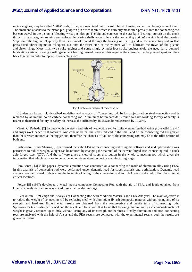
Fig. 1 Schematic diagram of connecting rod
K.Sudershan kumar, [1] described modeling and analysis of Connecting rod. In his project carbon steel connecting rod is
replaced by aluminum boron carbide connecting rod. Aluminium boron carbide is found to have working factory of safety is
nearer to theoretical factory of safety, to increase the stiffness by 48.55%andtoreducestress by 10.35%.
Vivek. C. Pathade, [2] he dealt with the stress analysis of connecting rod by finite element method using pro-e wild fire 4.0
and ansys work bench 11.0 software. And concluded that the stress induced in the small end of the connecting rod are greater
than the stresses induced at the bigger end, therefore the chances of failure of the connecting rod may be at the fillet section of
both end.
Pushpendra Kumar Sharma, [3] performed the static FEA of the connecting rod using the software and said optimization was
performed to reduce weight. Weight can be reduced by changing the material of the current forged steel connecting rod to crack
able forged steel (C70). And the software gives a view of stress distribution in the whole connecting rod which gives the
information that which parts are to be hardened or given attention during manufacturing stage.
Ram Bansal, [4] in his paper a dynamic simulation was conducted on a connecting rod made of aluminum alloy using FEA.
In this analysis of connecting rod were performed under dynamic load for stress analysis and optimization. Dynamic load
analysis was performed to determine the in service loading of the connecting rod and FEA was conducted to find the stress at
critical locations.
Folgar [5] (1987) developed a Metal matrix composite Connecting Rod with the aid of FEA, and loads obtained from
kinematic analysis. Fatigue was not addressed at the design stage.
S.Venkatesh [6] “Design and Analysis of Connecting Rod with Modified Materials and FEA Analysis‖ The main objective is
to reduce the weight of connecting rod by replacing steel with aluminium fly ash composite material without losing any of its
strength and hardness. Experimental results are obtained from the compressive and tensile tests of connecting rods.
Spectrometer test is also performed and the results are found out. It is found that by using aluminium fly ash composite material
weight is greatly reduced up to 50% without losing any of its strength and hardness. Finally aluminium and steel connecting
rods are analyzed with the help of Ansys and the FEA results are compared with the experimental results both the results are
give equal value.
JASC: Journal of Applied Science and Computations
Volume VI, Issue VI, JUNE/2019
ISSN NO: 1076-5131
Page No:1669

II. DESIGN OF CONNECTING ROD
A connecting rod is a machine member which is subjected to alternating direct compressive and
tensile forces. Since the compressive forces are much higher than the tensile force, therefore the cross-section of the connecting
rod is designed as a I-section and the Rankine formula is used. A connecting rod subjected to an axial load W may buckle
with x-axis as neutral axis in the plane of motion of the connecting rod,{or} y-axis is a neutral axis. The connecting rod is
considered like both ends hinged for Buckling about x-axis and both ends fixed for buckling about y-axis. A connecting rod
should be equally strong in buckling axis.
According to Rankine formulae
Wcr about x-axis
[* for both ends hinged L = l ]
Wcr about y-axis
[*for both ends fixed L = l/2 ]
In order to have a connecting rod equally strong in buckling about both the axis, the buckling loads most are equal. i.e.
[or]
This shows that the connecting rod is four times strong in buckling about y-axis than about-axis. If I xx > 4Iyy, Then
buckling will occur about y-axis and if I xx < 4Iyy,then buckling will occur about x-axis .In Actual practice I xx is kept slightly
less than 4Iyy. It is usually taken between 3 and 3.5 and the Connecting rod is designed for buckling about x-axis. The design
will always be satisfactory for buckling about y-axis. The most suitable section for the connecting rod is I-section with the
proportions shown mfg.
Area of the cross section
Moment of inertia about x-axis
Moment of inertia about x-axis
And moment of inertia about y-axis
= 3.2
There are two beam sections for designing connecting rod, i.e. I- section & H-section connecting rod.
III. FORCES ACTING ON THE CONNECTING ROD
1. All The combined effect (or joint effect) of,
a) The pressure on the piston, combined with the inertia of the Reciprocating parts.
b) The friction of the piston rings, piston, piston rod and the cross head.
2. The longitudinal component of the inertia of the rod.
JASC: Journal of Applied Science and Computations
Volume VI, Issue VI, JUNE/2019
ISSN NO: 1076-5131
Page No:1670
3. The transverse component of the inertia of the rod.
4. The friction of the two end bearings.
Different forces: 1. Axial forces resulting from gas pressure and inertia of piston assembly modified by the side thrust arising in consequence of
the connecting rod crank angle. The maximum axial load is compressive (at TDC).
2. Tensile stresses occur after firing, due to piston inertia.
3. Bending stress also occurs after firing.
4. Transverse forces Known as whip are caused by inertia effects of the rod mass. Fortunately axial &
transverse forces do not occur at the same time.
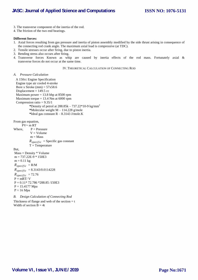
IV. THEORETICAL CALCULATION OF CONNECTING ROD
A. Pressure Calculation
A 150cc Engine Specification
Engine type air cooled 4-stroke
Bore x Stroke (mm) = 57x58.6
Displacement = 149.5 cc
Maximum power = 13.8 bhp at 8500 rpm
Maximum torque = 13.4 Nm at 6000 rpm
Compression ratio = 9.35/1
*Density of petrol at 288.85k – 737.22*10-9 kg/mm2
*Molecular weight M – 114.228 g/mole
*Ideal gas constant R – 8.3143 J/mole.K
From gas equation,
PV= m RT
Where, P = Pressure
V = Volume
m = Mass
𝑅𝑠𝑝𝑒𝑐𝑖𝑓𝑖𝑐 = Specific gas constant
T = Temperature
But,
Mass = Density * Volume
m = 737.22E-9 * 150E3
m = 0.11 kg
𝑅𝑠𝑝𝑒𝑐𝑖𝑓𝑖𝑐 = R/M
𝑅𝑠𝑝𝑒𝑐𝑖𝑓𝑖𝑐 = 8.3143/0.0114228
𝑅𝑠𝑝𝑒𝑐𝑖𝑓𝑖𝑐 = 72.76
P = mRT/ V
P = 0.11* 72.786 *288.85 /150E3
P = 15.4177 Mpa
P ≈ 16 Mpa
B. Design Calculation of Connecting Rod
Thickness of flange and web of the section = t
Width of section B = 4t
JASC: Journal of Applied Science and Computations
Volume VI, Issue VI, JUNE/2019
ISSN NO: 1076-5131
Page No:1671

Fig. 2 Standard dimension‘s of I-section
Height of the section H = 5t
Area of section A = 2(4t × t) +3t × t
A = 11𝑡2
M.O.I of section about x-axis:
= 34.91𝑡4
M.O.I of section about y-axis:
= 10.91𝑡4
𝐼𝑥𝑥 𝐼𝑦𝑦 = 3.2
So, in this case of this section (I-section) proportions shown above will be satisfactory. The most suitable section for the
connecting rod is I–section with proper proportions.
Length of the connecting rod (L) = 2 times of the stroke
L = 117.2 mm
Bucking load, F = 𝑊𝐵
Total acting load F = 𝐹𝑝 -𝐹𝑖 Where,
𝐹𝑝 = force acting on piston
𝐹𝑖= force by inertia
𝐹𝑝= π𝒅𝟐/ 4 * gas pressure
𝐹𝑝= 39473.1543 N
𝑊𝒓 = Weight of the reciprocating parts
𝑊𝒓 = 1.6 * 9.81
𝑊𝒓 = 15.696 N
Where, r = crank radius
r = stroke of piston / 2
r = 58.6 / 2
r = 29.3 mm
ϴ = crank angle from the dead centre
ϴ = 0 considering that connecting rod is at the TDC position
𝒏𝒍 = length of the connecting rod / crank radius
JASC: Journal of Applied Science and Computations
Volume VI, Issue VI, JUNE/2019
ISSN NO: 1076-5131
Page No:1672

𝒏𝒍 = 117.2 / 29.3
𝒏𝒍 = 4
g = acceleration due to gravity = 9.81
v = crank velocity, m/s
w = 𝟐𝝅𝒏
𝟔𝟎
w = 𝟐𝝅×𝟖𝟓𝟎𝟎𝟎
𝟔𝟎 = 890.1179 N
v = wr = 890.1179 × 29.3𝒆−𝟑 = 26.08 m/s
On substituting above values in 𝑭𝒊 Equation,
We get,𝑭𝒊 = 9285.5481 N
Therefore,
F = 𝑭𝒑 - 𝑭𝒊
F = 39473.1543 -9285.5481
F = 30187.6062 N = 𝑾𝑩
For Aluminium6061-1.5%𝑩𝟒C- 1.5%SiC
Buckling load,
Where,
𝝈𝒄 = compressive yield stress = 390 Mpa
𝑲𝒙𝒙 = 𝑰𝒙𝒙
𝑨
𝑲𝒙𝒙 = 1.78 t
a = 𝝈𝒄 /𝝅𝟐E
a = 0.0028
By substituting 𝝈𝒄 , A, a, L, 𝑲𝒙𝒙 on buckling load 𝑾𝑩 then
We get,
30187.6062 = 326.48𝒕𝟒
𝒕𝟒 = 92.4
t = 3.1 mm
Width of section, B = 4t
B = 4× 3.1
B = 12.4 mm
Height of the section, H = 5t
H = 5× 3.1
H = 15.5 mm
Area of the section, A = 11𝒕𝟐
A = 11 × 𝟑.𝟏𝟐
A = 105.71 𝒎𝒎𝟐
Height at the big end (crank end) = 𝑯𝟐 = 1.1H to 1.25H
𝑯𝟐 = 1.1 ×15.5
𝑯𝟐 = 17.05 mm
Height at the small end (piston end) = 𝑯𝟏 = 0.9 H to 0.75H
𝑯𝟏 = 0.9 × 15.5
𝑯𝟏 = 13.95 mm
Small end (Piston end):
Inner diameter of small end 𝒅𝟏 = 𝑭𝒈 / (𝑷𝒃𝟏×𝒍𝟏)
JASC: Journal of Applied Science and Computations
Volume VI, Issue VI, JUNE/2019
ISSN NO: 1076-5131
Page No:1673

[ 𝑭𝒊 = 𝑭𝒈 = 9285.5481 N ]
𝒅𝟏 = 𝟗𝟐𝟖𝟓.𝟓𝟒𝟖𝟏
𝟏𝟐.𝟓×𝟏.𝟓𝒅𝟏
𝒅𝟏𝟐
= 495.23
𝒅𝟏 = 22.25 mm
Where,
Design bearing pressure for small end 𝑷𝒃𝟏 = 12.5 to 15.4 N/𝒎𝒎𝟐
Length of the piston pin 𝒍𝟏 = (1.5 to 2) 𝒅𝟏
Outer diameter of the small end 𝒅′𝟏 = 𝒅𝟏+ 2𝒕𝒃 + 2𝒕𝒎
𝒅′𝟏 = 22.25 + [2×2] + [2×5]
𝒅′𝟏= 36.25 mm
Where,
Thickness of the bush ( 𝒕𝒃) = 2 to 5 mm
Marginal thickness (𝒕𝒎) = 5 to 15 mm
Big end (Crank end)
Inner diameter of big end 𝒅𝟐 = 𝑭𝒈 / ( 𝑷𝒃𝟐 × 𝒍𝟐 )
𝒅𝟐 = 𝟗𝟐𝟖𝟓.𝟓𝟒𝟖𝟏
𝟏𝟎.𝟖×𝟏 𝒅𝟐
𝒅𝟐 = 29.32 mm
Where,
Design bearing pressure for big end 𝑷𝒃𝟐 = 10.8 to 12.6 N/𝒎𝒎𝟐
Length of the crank pin 𝒍𝟐 = (1 to 1.25) 𝒅𝟐
Root diameter of bolt = ( 𝟐𝑭𝒊𝒎
𝝅×𝑺𝒕 ) ^2
= 4 mm
Outer diameter of big end 𝒅𝟐′ = 𝒅𝟐 + 2𝒕𝒃 + 2𝒅𝒃 +2 𝒕𝒎
𝒅𝟐′ = 29.32 + [2×2] + [2×4.8] + [2×5]
𝒅𝟐′ = 52.92 mm
Where,
Thickness of the bush (𝒕𝒃) = 2 to 5 mm
Marginal thickness (𝒕𝒎 ) = 5 to 15 mm
Nominal diameter of the bolt (𝒅𝒃) = 1.2 × root diameter of bolt
𝒅𝒃 = 1.2 × 4
𝒅𝒃 = 4.8 mm
Fig. 3 General Dimensions of Connecting rod
C. Specifications of connecting rod (aluminium 6061-1.5% B4 C-1.5 SiC)
TABLE I
JASC: Journal of Applied Science and Computations
Volume VI, Issue VI, JUNE/2019
ISSN NO: 1076-5131
Page No:1674

S. No Parameters ( mm )
1. Thickness of the connecting rod ( t ) = 3.1 mm
2. Width of the section ( B ) = 12.4 mm
3. Height of the section ( H ) = 15.5 mm
4. Height at the big end (H2) = 17.05 mm
5. Height at the small end ( H1) = 13.95 mm
6. Inner diameter of the small end = 22.25 mm
7. Outer diameter of the small end = 36.25 mm
8. Inner diameter of the big end = 29.32 mm
9. Outer diameter of big end = 52.92 mm
D. Material properties used for analysis
TABLE II
S.
No Parameters
Old material
(Al360)
New materials (Al6061-
1.5%B4C-1.5%SiC)
1. Ultimate tensile strength (Mpa) 303Mpa 422Mpa
2. Yield strength (Mpa) 170Mpa 390Mpa
3. Young ‗s modulus 60Gpa 293.63Gpa
4. Poisson‘s ratio 0.33 0.33
5. Density (g/ cm3) 2.6 g/cm
3 2.7 g/ cm
3
V. FEA OF CONNECTING ROD
JASC: Journal of Applied Science and Computations
Volume VI, Issue VI, JUNE/2019
ISSN NO: 1076-5131
Page No:1675

Fig. 4 Model of connecting rod
Fig. 5 Meshed Model of connecting rod
VI. RESULTS AND DISCUSSION
Analysis
For finite element analysis 16 Mpa of pressure is used. The analysis is carried out using ANSYS software. The pressure is
applied at the small end of connecting rod keeping big end fixed. The maximum and minimum von-misses stress, strain and
displacement are noted from the ANSYS.
1. EQUIVALENT STRESS:
Fig. 6 Equivalent Stress for Al6061-1.5% B4C-1.5% SiC
2. EQUIVALENT STRAIN
JASC: Journal of Applied Science and Computations
Volume VI, Issue VI, JUNE/2019
ISSN NO: 1076-5131
Page No:1676

Fig. 7 Equivalent Strain for Al6061-1.5% B4C-1.5% SiC
3. NORMAL STRESS (X-AXIS):
Fig. 8 Normal Stress for Al6061-1.5% B4C-1.5% SiC
4. NORMAL STRESS (Y-AXIS):
Fig. 9 Normal Stress (y-axis) for Al6061-1.5% B4C-1.5% SiC
5. NORMAL STRESS (Z-AXIS):
JASC: Journal of Applied Science and Computations
Volume VI, Issue VI, JUNE/2019
ISSN NO: 1076-5131
Page No:1677

Fig. 10 Normal stress (z-axis) for Al6061-1.5% B4C-1.5% SiC
6. SHEAR STRESS (XY-PLANE):
Fig. 11 Shear stress (xy-plane) for Al6061-1.5% B4C-1.5% SiC
7. SHEAR STRESS (YZ-PLANE):
Fig. 12 Shear stress (yz-plane) for Al6061-1.5% B4C-1.5% SiC
JASC: Journal of Applied Science and Computations
Volume VI, Issue VI, JUNE/2019
ISSN NO: 1076-5131
Page No:1678

8. SHEAR STRESS (ZX-PLANE):
Fig. 13 Shear stress (yz-plane) for Al6061-1.5% B4C-1.5% SiC
9. TOTAL DEFORMATION:
Fig. 14 Total Deformation for Al6061-1.5% B4C-1.5% SiC
10. DIRECTIONAL DEFORMATION (X-AXIS):
Fig. 15 Directional deformation (x-axis) for Al6061-1.5% B4C-1.5% SiC
JASC: Journal of Applied Science and Computations
Volume VI, Issue VI, JUNE/2019
ISSN NO: 1076-5131
Page No:1679

11. DIRECTIONAL DEFORMATION (Y-AXIS):
Fig. 16 Directional deformation (y-axis) for Al6061-1.5% B4C-1.5% SiC
12. DIRECTIONAL DEFORMATION (Z-AXIS):
Fig. 17 Directional deformation (z-axis) for Al6061-1.5% B4C-1.5% SiC
TABLE III
STRESSES AND DEFORMATION OF (AL6061-1.5%𝐵4C-1.5%SIC)
S. No Types MAX (Mpa) MIN (Mpa)
1. Equivalent stress 0.011766 1.8035𝑒−5
2. Normal stress (x-axis) 0.010455 -0.0029394
3. Normal stress (y-axis) 0.0044256 -0.0048708
4. Normal stress (z-axis) 0.0018303 -0.0011143
5. Shear stress (xy plane) 0.0030315 -0.002754
6. Shear stress (yz plane) 0.00072891 -0.00065184
7. Shear stress (zx plane) 0.0018352 -0.0020165
8. Total deformation 0.00010324 0
9. Directional deformation (x-axis) 0.00011614 0
10. Directional deformation (y-axis) 1.7986𝑒−5 -1.8102𝑒−5
JASC: Journal of Applied Science and Computations
Volume VI, Issue VI, JUNE/2019
ISSN NO: 1076-5131
Page No:1680

11. Directional deformation (z-axis) 2.4883𝑒−6 -1.9222𝑒−6
TABLE IV
STRAIN OF (AL6061-1.5%𝐵4C-1.5%SIC)
S. No Types MAX (mm) MIN (mm)
1. Equivalent strain 5.8828𝑒−8 9.0173𝑒−11
VOLUME, WEIGHT AND STIFFNESS OF THE CONNECTING ROD
a) For aluminium 360
The volume of the connecting rod used is 100829.348𝑚𝑚3. Therefore mass of the connecting rod for respective materials
are:
Weight = Volume* Density
Weight = 57472.72836 * 2.6𝑒−3
Weight = 268.1811grams
Weight = 0.268kg
Weight = 0.268*9.81 = 2.62908N
b) For aluminium 6061-1.5%𝐵4C- 1.5%SiC
The volume of the connecting rod used is 57472.72836𝑚𝑚3. Therefore mass of the connecting rod for respective materials
are:
Weight = Volume* Density
Weight = 57472.72836 * 2.7𝑒−3
Weight = 155.176367 grams
Weight = 0.15517kg
Weight = 0.15517*9.81 = 1.52055N
Therefore there is net difference of 127.145807 grams in the new connecting rod for the same volume, i.e., is 45.035%
reduction in weight.
Stiffness of the connecting rod
a) For aluminium 360
Weight of the connecting rod = 268.1811grams = 2.62908N
Deformation = 0.0010324
Stiffness = Weight / Deformation
Stiffness = 2.62908 / 0.0010324
Stiffness = 2546.5711N/mm
b) For aluminium 6061-1.5%𝐵4C- 1.5%SiC
Weight of the connecting rod = 155.176367
Deformation = 0.0001324
Stiffness = Weight / Deformation
Stiffness = 1.52055 / 0.00010324
Stiffness = 14728.303N/mm
VII. CONCLUSIONS
1. The Weight can be reduced by changing the material of the current Al360 connecting rod to hybrid al6061-1.5%𝐵4c- 1.5%
SiC.
2. The optimized connecting rod is 45.035% lighter than the current Al360 connecting rod.
3. The new optimized connecting rod is comparatively much stiffer than the Al360.
JASC: Journal of Applied Science and Computations
Volume VI, Issue VI, JUNE/2019
ISSN NO: 1076-5131
Page No:1681
REFERENCES
[1] K. Sudershan Kumar, K. Tirupathi Reddy, Syed Altaf Hussan ―Modeling and analysis of two Wheeler connecting rod‖, International Journal of Modern
Engineering Research, Vol -2, Issue- 5, pp-3367-3371, Sep-Oct-2012. [2] Vivek.C.Pathade, Bhumeshwar Patle, Ajay N. Ingale ―Stress Analysis of I.C. Engine Connecting Rod by FEM‖, International Journal of Engineering and
Innovative Technology, Vol-1, Issue-3, pp-12-15, March2012.
[3] Pushpendra Kumar Sharma1, Borse Rajendra R, ―Fatigue analysis and optimisation of connecting rod using finite element analysis‖, International Journal of advance research in Science and Engineering, Vol. No.1, Issue No. I, pp-3367-3371, September 2012.
[4] Ram Bansal, ―Dynamic simulation of connecting rod made of aluminium alloy using finite element analysis approach‖, IOSR Journal of Mechanical and
Civil Engineering, Volume 5, Issue 2, PP 01 -05, Jan. - Feb. 2013.
[5] Afzal, A. and A. Fatemi, 2004. "A comparative study of fatigue behavior and life predictions of forged steel and PM connecting rods". SAE Technical
Paper. [6] Chen, N., L. Han, W. Zhang and X. Hao, 2006. "Enhancing Mechanical Properties and Avoiding Cracks by Simulation of Quenching Connecting Rod".
Material Letters, 61: 3021-3024.
[7] El – Sayed, M.E.M. and E.H. Lund, 1990. ―Structural optimization with fatigue life constraints,‖ Engineering Fracture Mechanics, 37(6): 1149-1156.
[8] Jahed Motlagh, H.M. Nouban and M.H. Ashraghi, 2003. "Finite Element ANSYS". University of Tehran Publication, PP: 990.
[9] Khanali, M., 2006. "Stress analysis of frontal axle of JD 955 combines". M.Sc. Thesis. Thran University, 124.
[10] Repgen, B., 1998. ―Optimized Connecting Rods to Enable Higher Engine Performance and Cost Reduction,‖ SAE Technical Paper Series, Paper No.980882.
JASC: Journal of Applied Science and Computations
Volume VI, Issue VI, JUNE/2019
ISSN NO: 1076-5131
Page No:1682