design and analysis of micro gas · pdf fileturbine and compressor and to find out the results...
TRANSCRIPT

International Journal of Advances in Engineering Research http://www.ijaer.com
(IJAER) 2015, Vol. No. 10, Issue No. III, September e-ISSN: 2231-5152/ p-ISSN: 2454-1796
88
INTERNATIONAL JOURNAL OF ADVANCES IN ENGINEERING RESEARCH
DESIGN AND ANALYSIS OF MICRO GAS
TURBINE
*Mr.SATISH PERURI , **Mr.K L N MURTY, ***Mr.T.JAYANANDA KUMAR
*M.Tech student, Mechanical Engineering Department, GIET, RJY.
** Mechanical Engineering Department, GIET, RJY
*** Mechanical Engineering Department, GIET, RJY
ABSTRACT
The objective of this project is to design a micro gas turbine and too make a static analysis on its
turbine and compressor and to find out the results of maximum stress and total deformation in the
turbine and the compressor. This project does not include a CFD analysis on the turbine and compressor
which is necessary to optimise the design. Only a mean line design process is discussed in this project.
Keywords: Turbine, blades, nozzles and centrifugal compressors
1. INTRODUCTION
To develop a design methodology for a low pressure ratio centrifugal compressor, nozzle and
axial turbine.
Scope of the project:
Design of centrifugal compressor
Design of nozzle
Design of axial turbine
Static analysis and of axial turbine and centrifugal compressor.
The project deals with the design methodology for the design of a Centrifugal Compressor. The
1D design gives an initial design solution on the basis of which it can be decided if a complete
CFD analysis of the compressor is required.
The objective of this project is to design a micro gas turbine and too make a static
analysis on its turbine and compressor and to find out the results of maximum stress and total
deformation in the turbine and the compressor.
This project does not include a CFD analysis on the turbine and compressor which is
necessary to optimise the design. Only a mean line design process is discussed in this project.

International Journal of Advances in Engineering Research http://www.ijaer.com
(IJAER) 2015, Vol. No. 10, Issue No. III, September e-ISSN: 2231-5152/ p-ISSN: 2454-1796
89
INTERNATIONAL JOURNAL OF ADVANCES IN ENGINEERING RESEARCH
2. LITERATURE SURVEY
In 1922, the American engineer and teacher Harvey N Davis had patented an expansion turbine
of unusual thermodynamic concept. This turbine was intended to have several nozzle blocks each
receiving a stream of gas from different temperature level of high pressure side of the main heat
exchanger of a liquefaction apparatus.
First successful commercial turbine developed in Germany which uses an axial flow single stage
impulse machine. Later in the year 1936 it was replaced by an inward radial flow turbine based
on a patent by an Italian inventor, Guido Zerkowitz.
India has been lagging behind the rest of the world in this field of research and development.
Still, significant progress has been made during the past two decades. In CMERI Durgapur,
Jadeja developed an inward flow radial turbine supported on gas bearings for cryogenic plants.
The device gave stable rotation at about 40,000 rpm. The programme was, however,
discontinued before any significant progress could be achieved. Another programme at IIT
Kharagpur developed a turbo expander unit by using aerostatic thrust and journal bearings which
had a working speed up to 80,000 rpm. Recently Cryogenic Technology Division, BARC
developed Helium refrigerator capable of producing 1 kW at 20K temperature.
3. INTRODUCTION TO DESIGN PROCESS
The classical turbo-machinery design process begins with mean line performance modelling
calculations, once a cycle specification has been set freezes the design flow, speed and stage
pressure ratio or head rise.
When basic mean-line velocity triangles have been suitable optimized then blading methods are
used to design the required blade shapes. They may involve, either direct or inverse
computational methods or they should involve both flow solvers and fundamental design
rules.When appropriate passage contours and blade shapes, are obtained it is reasonable to go for
final levels of design optimization
4. GAS TURBINE
A gas turbine is a rotating engine that extracts energy from a flow of combustion gases that result
from the ignition of compressed air and a fuel (either a gas or liquid, most commonly natural
gas). It has an upstream compressor module coupled to a downstream turbine module, and a
combustion chamber(s) module (with igniter[s]) in between. Energy is added to the gas stream in
the combustor, where air is mixed with fuel and ignited. Combustion increases the temperature,
velocity, and volume of the gas flow. This is directed through a nozzle over the turbine’s blades,

International Journal of Advances in Engineering Research http://www.ijaer.com
(IJAER) 2015, Vol. No. 10, Issue No. III, September e-ISSN: 2231-5152/ p-ISSN: 2454-1796
90
INTERNATIONAL JOURNAL OF ADVANCES IN ENGINEERING RESEARCH
spinning the turbine and powering the compressor Energy is extracted in the form of shaft power,
compressed air, and thrust, in any combination, and used to power aircraft, trains, ships,
generators, and even tanks.
4.1 Micro turbine
Micro turbines are small combustion turbines which are having output ranging from 2 kW to 500
kW. The Evolution is from automotive and truck turbochargers, auxiliary power units (APUs)
for airplanes, and small jet engines. Micro turbines are a relatively new distributed generation
technology which is used for stationary energy generation applications. Normally they are
combustion turbine that produces both heat and electricity on a relatively small scale. A micro
(gas) turbine engine consists of a radial inflow turbine, a combustor and a centrifugal
compressor. It is used for outputting power as well as for rotating the compressor. Micro turbines
are becoming widespread for distributed power and co-generation (Combined heat and power)
applications. They are one of the most promising technologies for powering hybrid electric
vehicles. They range from hand held units producing less than a kilowatt, to commercial sized
systems that produce tens or hundreds of kilowatts. Part of their success is due to advances in
electronics, which allows unattended operation and interfacing with the commercial power grid.
Electronic power switching technology eliminates the need for the generator to be synchronized
with the power grid. This allows the generator to be integrated with the turbine shaft, and to
double as the starter motor. They accept most commercial fuels, such as gasoline, natural gas,
propane, diesel, and kerosene as well as renewable fuels such as E85, biodiesel and biogas.
4.2 Thermodynamic Heat Cycle

International Journal of Advances in Engineering Research http://www.ijaer.com
(IJAER) 2015, Vol. No. 10, Issue No. III, September e-ISSN: 2231-5152/ p-ISSN: 2454-1796
91
INTERNATIONAL JOURNAL OF ADVANCES IN ENGINEERING RESEARCH
Pressure ratio is considerably lower when a recuperator is used. Consequently, for good power
and efficiency, it is advantageous to operate the expansion turbine at the highest practical inlet
temperature consistent with economic turbine blade materials and to operate the compressor with
inlet air at the lowest temperature possible. The general trend in gas turbine advancement has
been toward a combination of higher temperatures and pressures. However, inlet temperatures
are generally limited to 1750°F or below to enable the use of relatively inexpensive materials for
the turbine wheel and recuperator. 4:1 is the optimum pressure ration for best efficiency in
recuperated turbines.
5. MODELLING OF A CENTRIFUGAL COMPRESSOR
A circle is drawn on the x-z plane and is extruded along the y- axis about a distance of 3mm.A
datum plane is created on the surface of the disk thus produced.
The profile for nozzle is drawn on this plane and this is extruded onto the circle and the material
is removed, using Boolean subtract. This extrude is performed 1mm more than the required.An
associative copy is then made of this feature (circular array) and we obtain the number of nozzles
we require.Then a circle with the inside diameter of the nozzle is drawn, extruded and united
with the previous circle.A hole is made on this nozzle for mounting it on the shaft using air
bearings or magnetic bearings.

International Journal of Advances in Engineering Research http://www.ijaer.com
(IJAER) 2015, Vol. No. 10, Issue No. III, September e-ISSN: 2231-5152/ p-ISSN: 2454-1796
92
INTERNATIONAL JOURNAL OF ADVANCES IN ENGINEERING RESEARCH
6 RESULTS AND DISCUSSIONS
Titanium Alloy
TABLE 1: Geometry
Model (A4) > Geometry
Object
Name Geometry
State Fully Defined
Definition
Source E:\Project\compressor 2.igs
Type Iges
Length
Unit Meters
Element
Control Program Controlled
Display Part Color
Style
Bounding Box
Length X 50. mm
Length Y 15.005 mm
Length Z 50. mm
Properties
Volume 9990.5 mm³
Mass 4.6156e-002 kg
Scale
Factor
Value
1.

International Journal of Advances in Engineering Research http://www.ijaer.com
(IJAER) 2015, Vol. No. 10, Issue No. III, September e-ISSN: 2231-5152/ p-ISSN: 2454-1796
93
INTERNATIONAL JOURNAL OF ADVANCES IN ENGINEERING RESEARCH
Statistics
Bodies 1
Active
Bodies 1
Nodes 37739
Elements 20508
Mesh
Metric None
Preferences
Import
Solid
Bodies
Yes
Import
Surface
Bodies
Yes
Import
Line
Bodies
No
Parameter
Processing Yes
Personal
Parameter
Key
DS
CAD
Attribute
Transfer
No
Named
Selection No
Processing
Material
Properties
Transfer
No
CAD
Associativi
ty
Yes
Import
Coordinate
Systems
No
Reader
Save Part
File
No
Import
Using
Instances
Yes
Do Smart
Update No
Attach File
Via Temp
File
Yes
Temporary
Directory
C:\Users\Amar\AppData\Local\
Temp
Analysis
Type 3-D
Mixed
Import
Resolution
None
Enclosure Yes

International Journal of Advances in Engineering Research http://www.ijaer.com
(IJAER) 2015, Vol. No. 10, Issue No. III, September e-ISSN: 2231-5152/ p-ISSN: 2454-1796
94
INTERNATIONAL JOURNAL OF ADVANCES IN ENGINEERING RESEARCH
and
Symmetry
Processing
TABLE 2
Model (A4) > Geometry > Parts
Object Name Part 1
State Meshed
Graphics Properties
Visible Yes
Transparency 1
Definition
Suppressed No
Stiffness Behavior Flexible
Coordinate System Default Coordinate
System
Reference
Temperature By Environment
Material
Assignment Titanium Alloy
Nonlinear Effects Yes
Thermal Strain
Effects Yes
Bounding Box
Length X 50. mm
Length Y 15.005 mm
Length Z 50. mm
Properties
Volume 9990.5 mm³
Mass 4.6156e-002 kg
Centroid X -5.2581e-004 mm
Centroid Y 4.0649 mm
Centroid Z -2.2049e-003 mm
Moment of Inertia
Ip1 5.4201 kg·mm²
Moment of Inertia
Ip2 9.6012 kg·mm²
Moment of Inertia
Ip3 5.4164 kg·mm²
Statistics
Nodes 37739
Elements 20508
Mesh Metric None
TABLE 3
Model (A4) > Coordinate Systems >
Coordinate System
Object Name Global Coordinate
System

International Journal of Advances in Engineering Research http://www.ijaer.com
(IJAER) 2015, Vol. No. 10, Issue No. III, September e-ISSN: 2231-5152/ p-ISSN: 2454-1796
95
INTERNATIONAL JOURNAL OF ADVANCES IN ENGINEERING RESEARCH
State Fully Defined
Definition
Type Cartesian
Ansys System
Number 0.
Origin
Origin X 0. mm
Origin Y 0. mm
Origin Z 0. mm
Directional Vectors
X Axis Data [ 1. 0. 0. ]
Y Axis Data [ 0. 1. 0. ]
Z Axis Data [ 0. 0. 1. ]
TABLE 4
Model (A4) > Mesh
Object Name Mesh
State Solved
Defaults
Physics Preference Mechanical
Relevance 0
Sizing
Use Advanced Size Off
Function
Relevance Center Fine
Element Size Default
Initial Size Seed Active Assembly
Smoothing Medium
Transition Fast
Span Angle Center Fine
Minimum Edge
Length 0.652250 mm
Inflation
Use Automatic Tet
Inflation None
Inflation Option Smooth Transition
Transition Ratio 0.272
Maximum Layers 5
Growth Rate 1.2
Inflation Algorithm Pre
View Advanced
Options No
Advanced
Shape Checking Standard
Mechanical
Element Midside Program Controlled

International Journal of Advances in Engineering Research http://www.ijaer.com
(IJAER) 2015, Vol. No. 10, Issue No. III, September e-ISSN: 2231-5152/ p-ISSN: 2454-1796
96
INTERNATIONAL JOURNAL OF ADVANCES IN ENGINEERING RESEARCH
Nodes
Straight Sided
Elements No
Number of Retries Default (4)
Rigid Body Behavior Dimensionally
Reduced
Mesh Morphing Disabled
Pinch
Pinch Tolerance Please Define
Generate on Refresh No
Statistics
Nodes 37739
Elements 20508
Mesh Metric None
TABLE 5: Static Structural (A5)
Model (A4) > Analysis
Object Name Static Structural
(A5)
State Solved
Definition
Physics Type Structural
Analysis Type Static Structural
Solver Target ANSYS
Mechanical
Options
Environment
Temperature 22. °C
Generate Input Only No
TABLE 6
Model (A4) > Static Structural (A5) >
Analysis Settings
Object
Name Analysis Settings
State Fully Defined
Step Controls
Number Of
Steps 1.
Current Step
Number 1.
Step End
Time 1. s
Auto Time
Stepping Program Controlled
Solver Controls
Solver Type Program Controlled
Weak
Springs Program Controlled
Large Off

International Journal of Advances in Engineering Research http://www.ijaer.com
(IJAER) 2015, Vol. No. 10, Issue No. III, September e-ISSN: 2231-5152/ p-ISSN: 2454-1796
97
INTERNATIONAL JOURNAL OF ADVANCES IN ENGINEERING RESEARCH
Deflection
Inertia
Relief Off
Nonlinear Controls
Force
Convergence Program Controlled
Moment
Convergence Program Controlled
Displacemen
t
Convergence
Program Controlled
Rotation
Convergence Program Controlled
Line Search Program Controlled
Output Controls
Calculate
Stress Yes
Calculate
Strain Yes
Calculate
Contact No
Calculate
Results At All Time Points
Analysis Data Management
Solver Files
Directory E:\Project\Compressor
analysis_files\dp0\SYS\MEC
H\
Future
Analysis None
Scratch
Solver Files
Directory
Save
ANSYS db No
Delete
Unneeded
Files
Yes
Nonlinear
Solution No
Solver Units Active System
Solver Unit
System nmm
TABLE 7
Model (A4) > Static Structural (A5) >
Loads
Object
Name
Fixed
Supp
ort
Press
ure
Press
ure 2
Press
ure 3
Press
ure 4
State Fully Defined
Scope
Scoping
Method Geometry Selection
Geomet 1 Face

International Journal of Advances in Engineering Research http://www.ijaer.com
(IJAER) 2015, Vol. No. 10, Issue No. III, September e-ISSN: 2231-5152/ p-ISSN: 2454-1796
98
INTERNATIONAL JOURNAL OF ADVANCES IN ENGINEERING RESEARCH
ry
Definition
Type
Fixed
Supp
ort
Pressure
Suppres
sed No
Define
By Components
Coordin
ate
System Global Coordinate System
X
Compo
nent 0. MPa (ramped)
Y
Compo
nent -0.2 MPa (ramped)
Z
Compo
nent 0. MPa (ramped)
Model (A4) > Static Structural (A5) >
Pressure
FIGURE 15
Model (A4) > Static Structural (A5) >
Pressure 4
TABLE 8
Model (A4) > Static Structural (A5) >
Loads
Object
Name
Press
ure 5
Press
ure 6
Press
ure 7
Press
ure 8
Press
ure 9
State Fully Defined
Scope
Scoping
Method Geometry Selection

International Journal of Advances in Engineering Research http://www.ijaer.com
(IJAER) 2015, Vol. No. 10, Issue No. III, September e-ISSN: 2231-5152/ p-ISSN: 2454-1796
99
INTERNATIONAL JOURNAL OF ADVANCES IN ENGINEERING RESEARCH
Geomet
ry 1 Face
Definition
Type Pressure
Define
By Components
Coordin
ate
System
Global Coordinate System
X
Compo
nent
0. MPa (ramped)
Y
Compo
nent
-0.2 MPa (ramped)
Z
Compo
nent
0. MPa (ramped)
Suppres
sed No
FIGURE 7
Model (A4) > Static Structural (A5) >
Pressure 7
TABLE 9
Model (A4) > Static Structural (A5) >
Loads
Object
Name
Press
ure
10
Press
ure
11
Press
ure
12
Press
ure
13
Press
ure
14
State Fully Defined
Scope
Scoping
Method Geometry Selection
Geomet
ry 1 Face
Definition
Type Pressure
Define
By Components
Coordin
ate Global Coordinate System
International Journal of Advances in Engineering Research http://www.ijaer.com
(IJAER) 2015, Vol. No. 10, Issue No. III, September e-ISSN: 2231-5152/ p-ISSN: 2454-1796
100
INTERNATIONAL JOURNAL OF ADVANCES IN ENGINEERING RESEARCH
System
X
Compo
nent
0. MPa (ramped)
Y
Compo
nent
-0.2 MPa (ramped)
Z
Compo
nent
0. MPa (ramped)
Suppres
sed No
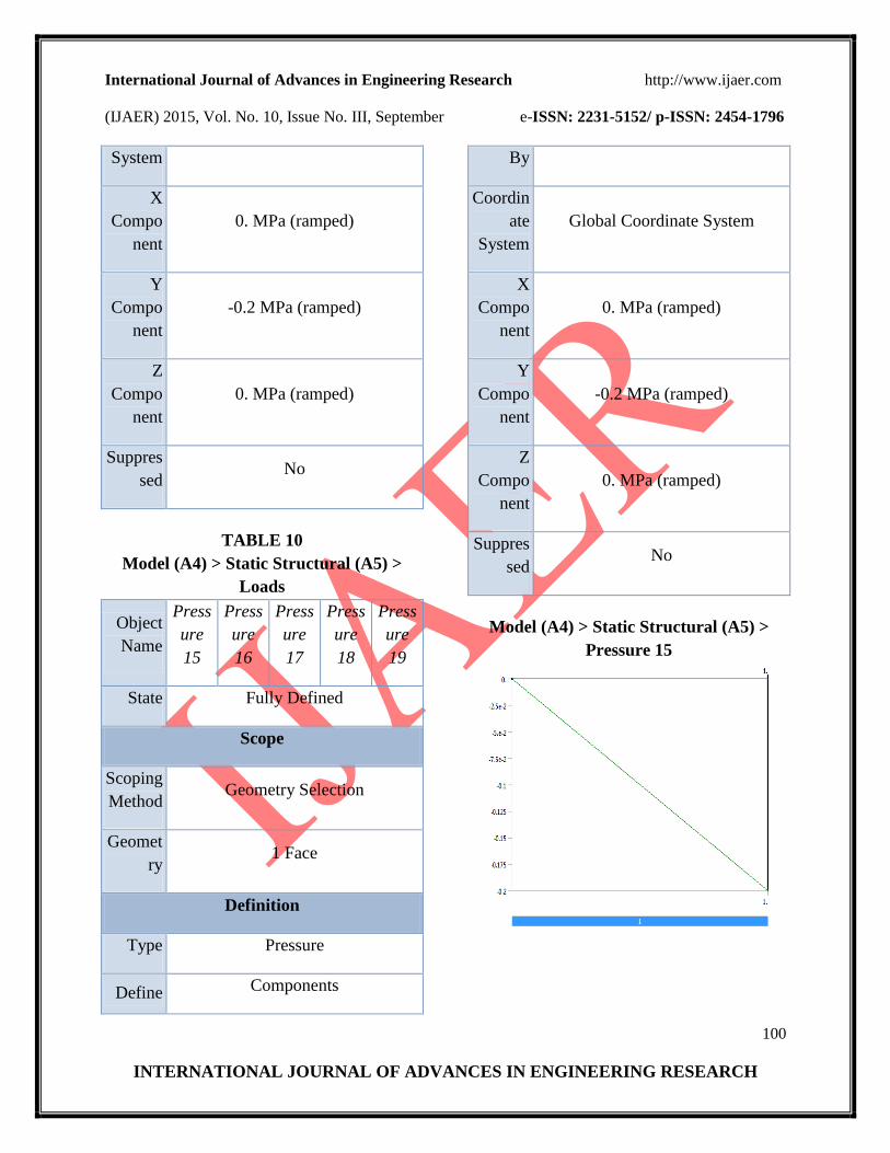
TABLE 10
Model (A4) > Static Structural (A5) >
Loads
Object
Name
Press
ure
15
Press
ure
16
Press
ure
17
Press
ure
18
Press
ure
19
State Fully Defined
Scope
Scoping
Method Geometry Selection
Geomet
ry 1 Face
Definition
Type Pressure
Define Components
By
Coordin
ate
System
Global Coordinate System
X
Compo
nent
0. MPa (ramped)
Y
Compo
nent
-0.2 MPa (ramped)
Z
Compo
nent
0. MPa (ramped)
Suppres
sed No
Model (A4) > Static Structural (A5) >
Pressure 15
International Journal of Advances in Engineering Research http://www.ijaer.com
(IJAER) 2015, Vol. No. 10, Issue No. III, September e-ISSN: 2231-5152/ p-ISSN: 2454-1796
101
INTERNATIONAL JOURNAL OF ADVANCES IN ENGINEERING RESEARCH
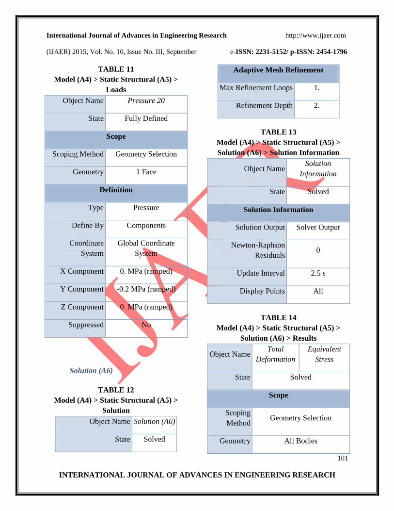
TABLE 11
Model (A4) > Static Structural (A5) >
Loads
Object Name Pressure 20
State Fully Defined
Scope
Scoping Method Geometry Selection
Geometry 1 Face
Definition
Type Pressure
Define By Components
Coordinate
System
Global Coordinate
System
X Component 0. MPa (ramped)
Y Component -0.2 MPa (ramped)
Z Component 0. MPa (ramped)
Suppressed No
Solution (A6)
TABLE 12
Model (A4) > Static Structural (A5) >
Solution
Object Name Solution (A6)
State Solved
Adaptive Mesh Refinement
Max Refinement Loops 1.
Refinement Depth 2.
TABLE 13
Model (A4) > Static Structural (A5) >
Solution (A6) > Solution Information
Object Name Solution
Information
State Solved
Solution Information
Solution Output Solver Output
Newton-Raphson
Residuals 0
Update Interval 2.5 s
Display Points All
TABLE 14
Model (A4) > Static Structural (A5) >
Solution (A6) > Results
Object Name Total
Deformation
Equivalent
Stress
State Solved
Scope
Scoping
Method Geometry Selection
Geometry All Bodies

International Journal of Advances in Engineering Research http://www.ijaer.com
(IJAER) 2015, Vol. No. 10, Issue No. III, September e-ISSN: 2231-5152/ p-ISSN: 2454-1796
102
INTERNATIONAL JOURNAL OF ADVANCES IN ENGINEERING RESEARCH
Definition
Type Total
Deformation
Equivalent
(von-Mises)
Stress
By Time
Display
Time Last
Calculate
Time History Yes
Identifier
Results
Minimum 0. mm 4.2262e-002
MPa
Maximum 1.5471e-003
mm 9.4234 MPa
Information
Time 1. s
Load Step 1
Substep 1
Iteration
Number 1
Integration Point Results
Display
Option Averaged
Figure 17
Compressor Total Deformation
Figure 18
Compressor Stress Analysis
Figure 19
Compressor Stress Analysis
International Journal of Advances in Engineering Research http://www.ijaer.com
(IJAER) 2015, Vol. No. 10, Issue No. III, September e-ISSN: 2231-5152/ p-ISSN: 2454-1796
103
INTERNATIONAL JOURNAL OF ADVANCES IN ENGINEERING RESEARCH
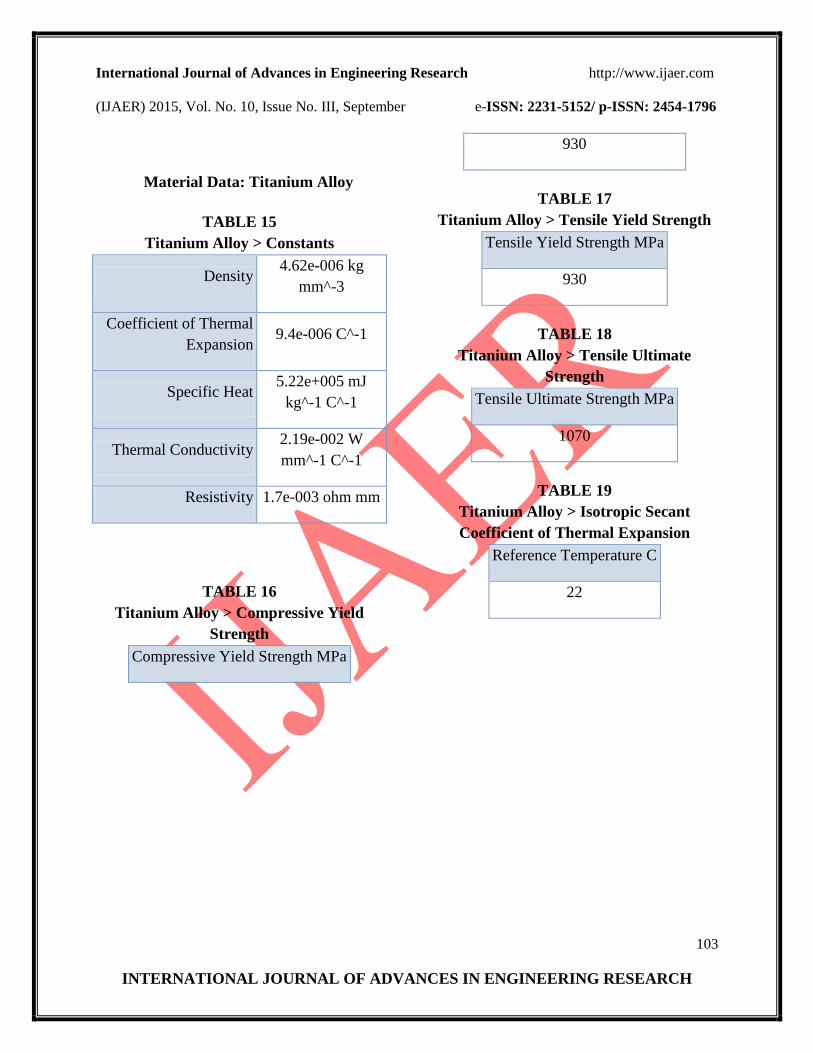
Material Data: Titanium Alloy
TABLE 15
Titanium Alloy > Constants
Density 4.62e-006 kg
mm^-3
Coefficient of Thermal
Expansion 9.4e-006 C^-1
Specific Heat 5.22e+005 mJ
kg^-1 C^-1
Thermal Conductivity 2.19e-002 W
mm^-1 C^-1
Resistivity 1.7e-003 ohm mm
TABLE 16
Titanium Alloy > Compressive Yield
Strength
Compressive Yield Strength MPa
930
TABLE 17
Titanium Alloy > Tensile Yield Strength
Tensile Yield Strength MPa
930
TABLE 18
Titanium Alloy > Tensile Ultimate
Strength
Tensile Ultimate Strength MPa
1070
TABLE 19
Titanium Alloy > Isotropic Secant
Coefficient of Thermal Expansion
Reference Temperature C
22

International Journal of Advances in Engineering Research http://www.ijaer.com
(IJAER) 2015, Vol. No. 10, Issue No. III, September e-ISSN: 2231-5152/ p-ISSN: 2454-1796
104
INTERNATIONAL JOURNAL OF ADVANCES IN ENGINEERING RESEARCH
7 CONCLUSIONS
The work presented in the report is an attempt at designing a micro turbine of a required power.
Extensive literature review was carried out to study the various aspects and applications of micro
turbines.
A suitable design procedure was chosen from the available methods to design different parts of
micro turbine. Unigraphics is used extensively for making parts with diff types of operations.
Then all the parts are assembled for making a complete turbine in unigraphics Assembly section.
Micro turbines are relatively new in the market and are attracting wide attention due to their
varied applications. Development of a sophisticated engineering product like micro turbine is a
continuous process. A lot of work is yet to be done on the design aspects before the micro
turbine can be readied for market consumption. The design procedure has to take into various
other parameters to make it suitable for practical applications. Also, manufacturing of such
complex shapes of minute size is another ongoing research work. Further research into the
design and manufacture process would result in production of even better micro turbines.
CFD analysis can be performed on the micro turbine developed using one dimensional mean line
flow analysis, in order to optimize the design. The efficiency of the system for power generation
can be increased by using a recuperator.
10 FUTURE SCOPES
From the design experience detailed in this report, conclusions and ideas for possible
future work were made.
A main goal of any future project should be to increase power output of the micro-turbine.
Possible methods to accomplish this include using modern airfoil shapes instead of flat flats for
turbine blades and adding a fixed stator stage (pre-swirler) upstream of rotating turbine to direct
inlet flow into turbine stage. Use different motors as generators might also change the power
outputs.Development of composite materials having higher tensile strengths is a promising
technology for the development of these components.The machining of the complicated micro
components can be accomplished using MEMS technology. Since there is a significant
development in MEMS technology, the production of these components using MEMS
technology is quite possible.Combustion chambers can be developed to bear higher temperatures
which leads to increase in power output.Engines will be developed to have lower specific fuel
consumption by improving the fuel inlet nozzles.Burning fuel more cleanly with fewer emissions
which will run more quietly is also possible. More air borne and ground engine-conditioning-

International Journal of Advances in Engineering Research http://www.ijaer.com
(IJAER) 2015, Vol. No. 10, Issue No. III, September e-ISSN: 2231-5152/ p-ISSN: 2454-1796
105
INTERNATIONAL JOURNAL OF ADVANCES IN ENGINEERING RESEARCH
monitoring equipment will be used such as vibration and oil analysers and radiometer sensors to
measure turbine blade temperature while the engine is operating.
11. REFERENCES
1. Gas Turbines by V. Ganesan
2. Fluid Mechanics and Hydraulic Machines by Modi & Seth
3. Fluid Mechanics by R. K. Bansal
4. A text book on Thermal Engineering by R. K. Rajput
5. Thermodynamics by P. K. Nag
6. A paper on micro turbine for power generation by Jan Peris, Dominiek Reynaerts, Filip
Verplaetsen
7. Applied Thermodynamics by D. J. Dunn
8. 8.Design and Simulation of 500W Ultra Micro gas turbine by Sangjo Han, Jeongmin Seo,
Jun-Young Park, Bum-Seog Choi*, and Kyu Hyung Do
9. A micro gas turbine by electro discharge machining by Jan Peris, Dominiek Reynaerts,
Filip Verplaetsen.
10. Design of Impellers based on flow conditions in a radial compressor with axial impeller
entry by Dr. Ing. H. Hasselgruber , Hannover
11. en.wikipedia.org/wiki/Computer-aided_design
12. en.wikipedia.org/wiki/Electrical discharge machining.