design and cc:mstrudion of joints in concrete … survey of present practice for joints in concrete...
TRANSCRIPT

A survey of present practice for joints in concrete
pavements.
J-/()·-50 Title No. 46-59
Design and Cc:mstrudion of Joints in Concrete Pavements*
By WILLIAM VAN BREEMENt and E. A. FI~NEY! _.
With- a supplement o,n~ -- ..
Struchiral Design of Joints· f.or AirpQrt Pavements • ~c" ', -:
By THOMAS B. PRINGLE§ ,_
SYNOPSIS
Tho basic fundamental conditio"ns involved in the d~sigri ari'd c~~-. struction of joints are discussed.··-: -V~iioUs types of joints- arid' load transfer devices arc described, as well as various forms o£ structural failure of joints. R.ecommendations are given for the design, fabrication and insta1lation of load-transfer devices, the construction and finishing of tho concrete surrounding the joint assembly and the sealing of joints. A supplement discusses joints for heavy duty airport pavements.
INTRODUCTION
As a part of the work of ACI Committee 325, Subcommittee 3 was established and assigned the subject of structural design. of jbints. This paper bas been prepared in cooperation with the members of that subcommittee and has for its purpose a ·-review of jointing practice in highway pavements as it exists today. In general, it includes the definition, description and function of joints, joint design, load-transf~r devices and their function, forms of joint failure and trends in joi~t design.
From all viewpoints, an ideal concrete pavement surface would be one consisting of a continuous ribbon of co:o-crete of uniform construction with no breaks in its continuity. Unfortunately, however, such a
*Prese!tted at the ACI 46th annual convention, Chicago, Ill., February 21, 1950. Title No. 46-59 is a part of copyrighted JOUlmA:L OF THE AMERlCAN Col:'fCRETI'l ll:'fSTITUTE, V. 21, No. 10, June 1950, Proceedings, V. 46. Separate prints are available at 60 cents each. Discussion (copies in triplicate) should reach the Institute not later than Sept. 1, 1950. Address 18263 W. McN~chols Rd., Detroit 10, Mich.
tMember American Concrete Institute, Engineer of Special Assignments, New Jersey State Highway De_I:!t., Trenton, N.J. ,
+Member American Concrete Institute, Research Engineer, Michigan State Highway Dept., Lansing, Mich. •
§Airport Engineer, Office of the Chief of Engineers, Dept. of the Al'my, Washington, D. C,
789

------------------------------
790 jOURNAL OF THE AMERICAN CONCRETE INSTITUTE June 1950
pavement cannot be economically achieved under present-day practice although studies are being conducted in an attempt to accomplish this, in effect, through the use of continuous, heavy reinforcement.
Because of its inherent weakness in tension, concrete is highly susceptible to cracking under tensile stresses, particularly those induced by volume changes due to temperature fluctuation, autogenous shrinkage of the concrete at c:arly age, or other causes. Even in the "continuously reinforced" design the concrete itself is not continuous. 'Vhen transverse joints are not included in the design they will, in effect, be supplied in the form of transverse cracks that will sooner or later occur. The nearest approach to obtaining an ideal pavement comparatively free from transverse cracks has been accomplished by dividing the pavement into a series of slabs by the introduction of joints of one kind or another, the slabs to be as long as possible consistent with practical design requirements and within economic limitations.
Depending upon their design, the function of such joints is to maintain within safe limits the stresses caused by expansion, contraction and warping of the concrete. Transverse joints are thus functionally classified as "expansion," ."contraction," and "warping" or "hinge" joints. Longitudinal joints, as the name implies, are placed lengthwise in the pavement and act essentially as continuous hinge or contraction joints, depending on the method of construction. If the longitudinal joints contain a filler they may also act as expansion joints, as may be the case in wide sections of airport pavement.
It may be said that every joint is potentially a source of structural weakness contributing to the ultimate deterioration of the pavement. They may also limit the load-carrying capacity of the entire structure. Since it is possible to design a concrete pavement slab strong enough to withstand combined warping, load anq. friction stresses for any predictable traffic condition and subgrade support, it would appear to be good engineering practice to reduce the number of joints to an absolute minimum, consistent with sound design principles.
The structural inadequacy of transverse joints has been fully appreciated by highway engineers for many years and many designs have been advanced as a solution to the problem. This is reflected in the voluminous literature on the subject. However, up to the present, the joint problem has not been fully solved, and perhaps it never will be unless a conscientious and concerted effort is made by those in authority to remedy the following serious deficiencies which, in general, have exercised a profound influen<;e on the design, construction, and per-formance of joints during past years: ·
1. The permission of wide latitude in the interpretation of pavement specifications,

-------- ------------------~--------------------
JOINTS IN C6NCRETE PAVEMENTS 791
2. The prevalence of considerable lenity in the inspection and control of construction processes.
3. Careless practices associated with the initial sealing of joints and the subsequent maintenance thereof.
4. The lack of a suitable joint filler and sealing compouild.
5. The inability of present subbase construction practices to offer uniform and continuous support for the slabs.
6. The pmsuance of a short-sighted policy with respect to the cost of joint assemblies and load-transfer devices without full appreciation of their relative mechanical efficiency or their effect upon the ultimate service life of the structure.
7. The comparatively slow progress being made in the development of basic information and sou11d design theories in relation to joints.
8. The general practice of allowing steel fabricators .or others, rather than state and federal agencies, to take the initiative in joint design.
After more than a half century of experience in the design and construction of concrete pavements, there is still no generally uniform practice for either the usc and spacing of joints or the design and construction of the joints themselves. It is doubtful, however, whether uniform practice may ever b~ achieved, or in fact even be desirable, in vie-w of the many variations in climatic, traffic and soil conditions in the United States. We nevertheless firmly believe that present jointing practice can be materially improved by (1) correcting, so far as is practical, the deficiencies enumerated above and (2) coming to a mutual understanding on certain fundamentals of joint practice common to all-subgrade support, workmanship and specifications for the evaluation, spacing and placing of load-transfer devices in joints.
FUNCTION, DESCRIPTION AND DEFINITION OF TRANSVERSE JOINTS
In general, a transverse joint may be defined as an artificially created plane of interruption in the continuity of the pavement. The joints divide the pavement into a series of slabs of predetermined length. Since there are several kinds or types of transverse joints, some discussion should be devoted to their basic features and specific functions.
Because of the general looseness in the use of descriptive terms· for the various types of joints it is believed desirable at this point to assign definite terms to each kind and type to avoid ambiguity and misunderstanding. For the sake of clarity and mutual understanding, definitions and functions of the respective joints ani presented below. It is hoped that the terminology employed will eventually meet with general acceptance.
It may be stated that all types of joints can be placed in one of three basic categories, namely, "expansion," "contraction" and "hinge." Examples of joints falling in each of these three categories are presented in Fig. 1.

792 JOURNAL OF THE AMERICAN CONCRETE INSTITUTE June 1950
(EXPANSION J
t(CONTRACTJON
' 4
,,
' ' ' '
' 4
' 4
) '
A
' ' LOAD
4 TRANSfER OPTIONAL
-~-- ~----,-~--- 4'
~riLLED <>ROOVE OR
PREMOLOEO BITUMINOUS
' STRIP,
';:,. ~-
TRANSFER OPTIONAL
'· J .•
•4' ' .. ·_ . il.
'~ 4 A !J _ 1\_ .b
~~~w;:
,-~ «
"' .
A " 4
• 4 PLAT(.
4
~ ~
4
4. '· ., "
,. ,j·
' 4
4
4 4
,'· , •. ~_··,:~5,-,· J rl <> • A_ 4 . ~
~PLAIN OR KEYWAY •
80NDED"1
DOWELS OPTIONAL 4
.
A d ._L)" 4_d_ ·A ··A·'.<J.·,,_Ir_-4-.j.·.
w~"-o/~c
fig. 1-Three basic types of joints

JOINTS IN CONCRETE PAVEMENTS 793
Expansion joints
As the term implies, the primary function of an expansion joint is to provide for the expansion of the pavement and thus to maintain compressive stresses within safe limits. When installed between the pavement and a fixed structure, such as a bridge, an expansion joint serves also to prevent the pavement from exerting damaging pressures against the structure.
Expansion joints also function as contraction joints and, furthermore, permit vertical angular movement of the slab ends in the manner of hinged joints. They are usually constructed with an opening of % in. or 1 in., in which is installed a filler of some suitable resilient material such as premolded bituminous fiber board, wood, cork, or other material intended to provide expansion space and to prevent the infiltration of water and foreign substances. Actually, none of the materials so far used as joint filler has been able to exclude either water or foreign bodies completely. One of the most important functions of fillers, therefore, is to counteract the damaging effects of infiltrated solid materials by acting as a compressible gasket to prevent excessive localized restraint to joint closure. A major deficiency of all joint filler materials thus far employed is that they fail to recover in thickness after prolonged periods of compression and, therefore, in the course of time, fail to act as compressible gaskets. Desirable characteristics of filler material are relatively high resistance to compression, freedom from a tendency to extrude from the joints when compressed, and complete recovery in thickness after compression. The joint opening is usually sealed with a bituminous material, mixtures of bituminous material and rubber, or some mechanical sealing element. Slip dowels or proprietary loadtransfer devices are generally included.
Contraction j~ints
Contraction joints are installed in the pavement to maintain tensile stresses within safe limits. Since contraCtion joints must be free to open, the continuity of the longitudinal reinforcement, IT present, is interrupted at the joints. Dependence must be placed either on aggregate interlock or on load-transfer devices to maintain slab alignment.
Basically, there are two types of contraction joints, namely, the "plate-type" an"d the "groove-type," the latter being most commonly employed. '
Plate-type-Fig. 1 shows the typical features of a "plate-type" contraction joint. This joint is formed by erecting a separator or parting strip on the subgrade. The separator, which usually consists of a metal plate, or a thin sheet of some other rigid, non-,compressible material, serves to interrupt the continuity of the pavement. The groove formed

------ -----~~~~-----
794 JOURNAL OF THE AMERICAN CONCRETE INSTITUTE June 1950
in the concrete immediately above the separator serves as a reservoir for sealing material. A load-transfer device of some kind is generally used in conjunction with this type of joint, since interlocking of the aggregate is prevented by the separator.
Groove-type-In general, this type of joint is created by reducing the effective area of the cross section of the pavement by approximately one-third, thus causing the formation of a transverse crack at the joint. This is accomplished by either installing a thin premolded bituminous strip vertically to the desired depth or by forming a groove in the surface, as indicated in Fig. 1. In addition to the surface groove, a parting strip of -..vood, metal, or premolded material is sometimes provided at the bottom of the slab, directly under the groove, to insure tho formation
' of a vertical crack and to further encourage early cracking of the concreto at the joint.
:JVIost contraction joints, especially those of the groove type, are sealed with bituminous material or, more recently, by a rubber-asphalt compound, to exclude water and solid materials. It is not general practice to seal contraction joints employing premolded . bituminous strips to form tho groove.
Vertical slab alignment is usually maintained by aggregate interlock or the use of load-transfer devices.
Hinge joints
The term "hinge joint" applies to any joint vvhich permits hinge action but no appreciable separation of the adjacent slabs. Hinge joints are usually installed in conjunction with reinforced pavements and are intended primarily to control warping stresses. In contrast to contraction or expansion joints, appreciable changes in joint width are prevented by steel reinforcement or bonded steel dowels passing through the joint. In effect, a joint of this type acts simply as a hinge, that is, it merely permits a certain amount of vertical angular displacement of the abutting slabs (Fig. 1).
Hinge joints generally are constructed in the same manner as grooved contraction joints, except that in reinforced pavements the longitudinal reinfOrcement is not interrupted but is continuous through the joint, thereby allowing hinge action without appreciable slab separation. In the absence of reinforcement, bonded dowels are used to hold the slabs together. Load transfer is usually accomplished by aggregate interlock. For butt-type joints, other means may be employed. Tbe joints may or may not require sealing, depending upon their design.
Construction joints
This term applies to .the joint necessitated by any prolonged stoppage of the concreting operations, such as at the end of the day's work,
,! I

JOINTS IN CONCRETE PAVEMENTS 795
equipment breakdown, delays in delivery of materials, etc. It may be any one of the three types of joint-expansion, butt-type contraction, or hinge-depending upon the features of the pavement design and prevailing practice.
LONGITUDINAL JOINTS
Experience has shown that the full-width pavements constructed in the past h11ve been highly susceptible to longitudinal cracking, the location of the cracking being essentially along the center line. As a preventive measure, it is current practice to divide the pavement into lanes less than 15 ft. wide by longitudinal joints.
These joints appear at various longitudinal positions in the pavement, depending upon the width of construction, and serve to control tensile stresses. Longitudinal. joints generally fall in the category of hinge joints and may be constructed in one of several ways (Fig. 1). This type of joint may be an ordinary butt joint resulting from lane-at-atime construction, or one created under full-width construction by embedding a metal or fiber plate in the concrete along the proposed line of the joint and so shaped as to create an interlocking of the slab edges, or it may be created by weakening the pavement with a deeply formed groove, or "Yvith an c~beddcd strip of prefabricated bituminous material. The adjacent slabs are usually prevented from separating and faulting by means of bonded steel tie bars spaced at proper intervals. The joint may or may not be sealed, depending upon the manner of construction.
FACTORS IN JOINT DESIGN
The design of joints necessitates the consideration of certain structural features which enable the joint to perform its intended function, including:
1. Allowance for movement of slabs during expansion, contraction and warping, which in turn is dependent to a certain extent upon· (a) the length of slab or pavement section, (b) changes in original slab length due to autogenous volume changes and moisture conditions, (c) seasonal and daily temperature fluctuations with respect to construction temperatures, (d) subbase characteristics and (e) thermal coefficient of expansion of the concrete.
2. The iiLSurance of mutual vertical alignment of adjacent slabs to preserve desirable riding qualities.
3. Provision for load transfer, where necessru·y-including aggregate interlock and mechanical devices with their supporting systems.
4. Maintenance of adequate seal against infiltration of water 11nd foreign matter.
Joint width changes
It has been conclusively demonstrated by experimental field studies1
that joint width changes can be controlled by proper spacing of trans-

796 JOURNAL OF THE AMERICAN CONCRETE INSTITUTE June 1950
verse joints. The amplitude of joint width changes can be narrowed to any predetermined range for a given climate by sufficiently increasing the number of transverse joints to form proportionately shorter slabs. Some compromise usually is necessary between the two alternatives of least possible width change and smallest possible number of transverse joints, both of which are desirable features.
It is generally considered that the spacing and design of expansion joints should be dependent on the allowable compressive stress in the concr~te. The average compressive strength of cores from present-day concrete pavement at ages beyond 28 days generally ranges from 4000 to 6000 psi. Such strengths are well in excess of the theoretical compressive stresses resulting from thermal voll.1me changes which the concrete will be called upon to withstand under ordinary circumstances. Furthermore, compressive stresses are reduced at early ages because of the initial shrinkage of the concrete which takes place during the early hardening period, and may subsequently be reduced by plastic deformation of the concrete under continued compression.
Just how much compressive stress relief is provided by the above phenomena is not definitely known, but from stress calculations and the performance of experimental field sections constructed without expansion joints it seems safe to say that, in most cases, the compressive stress will not reach the values on which the pavement design is based, at least for some years. This does not mean, however, that the compressive stress at any given time cannot equal or exceed the strength of the concrete in certain localized areas, such as at joints and cracks.
Studies of blowups generally reveal that there had been a progressive deterioration of the quality of the concrete itself in the vicinity of joints prior to failure. Such deterioration is a contributing factor in the successive partial failures under excessive localized compressive stresses which eventually result in complete crushing or blowup of the joint. Infiltration of foreign materials plays a very important part in this process.
l\1any states have now omitted expansion joints except, in some instances, during cold weather construction, or to relieve horizontal pressures at bridge structures or other critical locations. When expansion joints are specified in these states, spacings of 400 to 600 feet are commonly used. The thought back of this practice is to relieve compressive stresses but not to eliminate them entirely since it is believed that a certain amotmt of compressive stress is desirable.
The amount of contraction joint opening in a given climate is a function of (a) their spacing, (b) the spacing of such expansion joints as may be included in the design, (c) temperatme prevailing during con-

JOINTS IN CONCRETE PAVEMENTS 797
struction and (d) the materials involved in the donstruction of the pavement. The maximum opening of contraction joints will, of course, be profoundly influenced by the extremes of temperature and moisture range characteristic of the prevailing climate.
There is now evidence 1 that \vhen contraction joints have once opened they seldom return to their original width even \Yhen the pavement is under compression. This increa'sc in residual joint opening with time is more pronounced as the spacing of the contraction· joints is increased, and the spacing of expansion joints decreased. J\1easurements of contraction joint openings under various joint Spacing conditions indicate that ultimate openings of as much _as 0.30 in. may be expected for 100-ft spacings when no expansion joints are used, and 0.50 in . .for 60-ft spacings 1vith l-in. expansion joints containing premolded bituminous filler spaced at 120-ft intervals.
Inasmuch as many engineers are reluctant to instaU contraction joints at the close intervals required to insure aggregate interlock, the current practice in some locations is to install the joints at intervals that range from 30 to 100 ft and to compensate for the loss in interlock by the installation of dowels or load-transfer devices.
Slab alignment
In addition to providing for expansion and contraction, as the case may be, it is the function of a joint, together with its_ load-transferring means, to preserve indefinitely the original riding qualities of the pavement. However, present design analysis for slab thickness does not take into consideration nonuniform subgrade conditions, subgrade volume changes caused by moisture and frost action, nor the pumping action and the subsequent faulting of slab ends resulting from decreasing subgrade support in the vicinity of joints. This latter phenomenon is associated with (1) continued consolidation of. granular subgrade material by vibratory effect of traffic over joint edges, (2) by the diluting effect of surface water which filters into these areas through open joints or by seepage at the sides of the pavement and (3) plastic deformation of the subgrade under load action, considering that the deflection of the slab ends may be three to five times that of the interior of the slab.
Experience indicates that to attain a continuing satisfactory riding pavement it is necessary, as an insurance measure, to provide a suitable load-transfer device having the twofold function of transferring the loads across the joint and maintaining the ·mutual alignment of the adjoining slab surfaces. By the introduction of such a device the deflection of the slab ends may be reduced approximately 50 percent, and the deflection of the slab ends relative to e,ach other almost 100 percent. To this end, joints must be designed to include, where necessary, satisfactory load-transfer devices together with appropriate holding assemblies.

-------------------------
798 JOURNAL OF THE AMERICAN CONCRETE INSTITUTE June 1950
Sealing of transverse joints
In spite of all care in the design of load-transfer units, or in the subsequent construction and installation of the joint assembly in the pavement, or in the final hand-finishing of the concrete at the joint, there remains one factor in the joint problem which has been sadly neglected and that is the development of vmys and means for constructing a transverse joint such that it will completely exclude water and solid foreign materials throughout the life of the pavement.
To seal a joint adequately, means must,be provided to exclude water and foreig•n matter from the top and bottom and also the ends. In the case of expansion joints, an attempt i~ now made to do this by inserting, into the joint opening, premolded filler materials sealed at the top, or wood boards. These materials are supposed to expand and contract in qnison with the slab ends and thus keep the joint opening closed.
Joint fillers-Consideration of providing the best possible type of joint filler material for expansion joints needs stimulation. Since the primary purpose of the joint filler is to prevent infiltration of foreign matter when the slabs are contracted and to support the joint-sealing compound at the top, the material should have the greatest possible resilience combined with the property of minimum extrusion under cyclic pressures. The bituminizcd fiber joint fillers in common use today have excellent nonextruding properties but, on the other hand, they possess little resilience. Wood boards have been used successfully for years by some states. At the present time, compressed wood is being given attention. The wood is compressed in the dry state to required thickness. When installed in the joint it has the potential property of expanding the amount compressed, plus normal swelling when saturated. Other premolded bituminized materials are available for expansion joint fillers. Sponge rubber sheeting has been suggested for this purpose. The problem of providing a suitable filler material must yet be solved. It is believed that industry can supply such a material if highway administrators would strongly demand it and be willing to pay the price.
The bituminized fiber parting strip so commonly used to form contraction joints offers no positive seal to the joints vvhen they are open during cold weather. Furthermore, because of its flexibility and instability, it is most difficult to install properly, even with careful workmanship. Consequently, spalling, scaling and subsequent disintegration of the concrete adjacent to the joints sometimes develop. The grooved type of joint properly sealed with a poured material offers many advantages.
Sealing com.po1<nds-Hot-poured asphalt-rubber compounds are widely used today for tbe sealing of all types of joints in concrete pavements.
~ 'I

JOINTS IN CONCRETE PAVEMENTS 799
As compared with the straight bituminous products they represent a marked advance in sealing materials, but the problem of adequately sealing joints is still far from solved. Experience now indicates that these materials are not doing an entirely satisfactory job even when applied under proper conditions. There is urgent need for improvement in these materials to produce better wetting and cohesive properties. Also, their application should not require such exact control, which is impractical to achieve under normal construction project conditions. Furthermore, there is need for considerable improvement in jointsealing material of this or any other type, and the development of more satisfactory test procedures to insure proper quality. Asphaltic oillatex joint-sealing material, although used to a limited extent, has shown remarkable durability in service. More recently, premolded neoprene rubber materials have appeared on the market.
The successful sealing of joints requires not only a suitable sealing material but also proper workmanship in applying it. Present specifications provide for such construction procedures, but they are seldom carried out conscientiously in the field. In other words, to insure positive adhesion of the joint-sealing material to the concr.ete, to effect a proper bond at all times, it will be necessary to provide methods to counteract deficiencies in the preparation of the joint smfaccs and in applying the materials.
Joint shields-It is now the practice in some states to provide a shield at bottom and sides of the joints to prevent infiltration of foreign material. Tbcse shields are approximately 12 in. wide and are made of sheet metal or premolded bituminous fiber board. Insufficient time has elapsed to form any definite conclusions as to the merit of this practice.
LOAD-TRANSFER DEVICES AND JOINT ASSEMBLIES
As previonsly indicated, load-transfer devices have a dual function, namely:
1. To prevent di.ITerential vertical displacement of the adjacent slab ends-such displacement being defined as "faulting" or 11stepping-of1."
2. To mechanically transfer loads across the joint space to the exLent that both slab ends will act jointly in supporting a load that is applied to only one of the slab ends-the result being a reduction in the magnitude of the deflections of the slab ends and a consequent reduction in the magnitude of the stresses induced in the pavement.
In recent years, due to the trernendous increases in both the weight and number of trucks, the action of traffic has become a factor of utmost importance in the design of joint devices. It should be understood, however, that the introduction of a load-transfer device of sufficient strength to cause both slab ends to deflect equally and simultaneously

800 JOURNAL OF THE AMERICAN CONCRETE INSTITUTE June 1950
under the action of traffic 1vill not necessarily result in a pavement that has uniform load-carrying capacity throughout its entire length. It has been demonstrated in actual practice that the pavement at joints and cracks is far more susceptible to faUure than elsewhere, and it is for this reason thnt the proper design of joints and the prevention or control of cracking 1varrant serious consideration.
Design of load-transfer devices
Load transfer as a factor in joint design ·was first recognized in 1917 when, on a concrete pavement project near Newport News, Va., steel dowels were placed across all transverse joints for the stated purpose of transmitting loads across the joints by shear. Since tbat time numerous patents have appeared covering all imaginable kinds of load-transfer devices. In most cases they were so expensive or impraetical to construct that they have never been used. 2
Although methods to provide structural interaction of adjoining slabs were used as early as 1917, it was not until 1928 that attention was given to the determination of spacing or to t:p_e evaluation of the effectiveness of such deviees. In that year, H. lVI. Westergaard3 presented a rational theory for joint design under the· title, 11Spacing of Dovvels." Several investigators 2•4•5 •6 •7 •8 •
9 have since presented theories and methods of tests for the evaluation of load~ transfer devices, together with results of field and laboratory studies.
The results of these investigations, particularly in regard to the functioning of load-transfer devices, indicate that there exists, in some cases, a close agreement between field tests and values obtained by theoretical calculations based on the Westergaard theory of slab deflections. A thorough study of these investigations is encouraging and gives evidence that a rational method of joint design can be established whereby a definite relationship bet\:veen the load-transfer device and the characteristics of the slab and subgrade may be utilized.
An examination of the load-transfer devices which have been used or are in use today reveals certain definite principles in their design. These principles may be classified as follows:
1. The development oJ shear resistance with hinge action. 2. The development of shear and bending moment. (The most common unit in
this class is tho conventional dowel bar.)
Further, ,a revie\v of load transfer practices for highway pavements10
brings out other interesting facts, namely: 1. The conventional round dowel is used to a greater extent than any other type
of load-trans1'cr device. The diameter ranges from % Lo 1}4' in., and the length from 12· to 33 in.
2. The spacing of the dowel bars ranges from 12 to 16Y2 in. center to center. Proprietary devices range in spacing from 12 to 20 in.
JOINTS IN CONCRETE PAVEMENTS
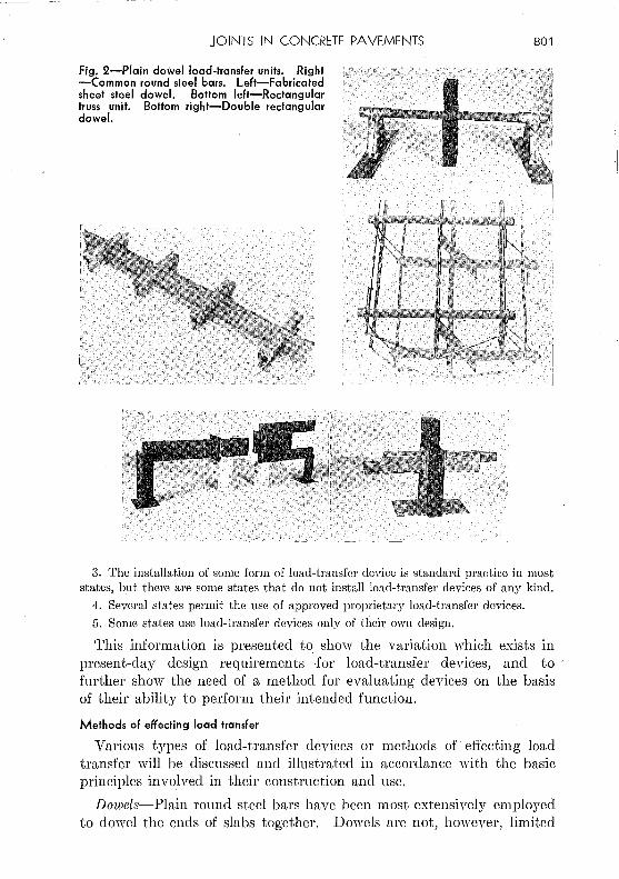
Fig. 2-Plain dowel load-transfer units. Right -Common round sleel bars. Left-Fabricated sheet steel dowel. Bottom left-Rectangular truss unit. Bottom right-Double rectangular dowel.
801
3. The installation of some form of load-transfer device is standard practice in most states, but there are some states that do not install load-transfer devices of any kind.
4. Several states permit the use of approved proprietary load-transfer devices.
5. Some states use load-transfer devices only of tlieir own design.
This information is presented to show the variation which exists in present-day design requirements ·for load-transfer devices, and to further show the need of a method for evaluating devices on the basis of their ability to perform their intended function.
Methods of effecting load transfer
Various types of load-transfer devices or methods of effecting load transfer will be discussed and illustrated in accordance with the basic principles involved in their construction and use.
Dowels-Plain round steel bars have been most extensively employed to dowel the ends of slabs together. Dowels are not, however, limited

I -
802 JOURNAL OF THE AMERICAN CONCRETE INSTITUTE June 1950
Left-H-Bar
Right-J-Bar (new)
Left.,-Dowel socket unit
Right-"A" dowel
Left-Wing bearing unit
Right-J-Bar (old)
Fig. 3-Dowel type load-transfer units with metal sleeves
to round sections, inasmuch as various structural sections such as rectangular bars, channels, !-beams and tubing have been employed. In this type, the dowel and concrete are in direct contact. Several well-known types are shown in Fig. 2.
Dowels with metal sleeves~Load-transfer units in this class have metal sleeves surrounding the dowel bar. The sleeves become embedded and anchored in the concrete. The function of the sleeves is to distribute the stresses into the concrete surrounding the load-transfer unit, thus preventing the highly concentrated bearing stresses that the dowels would otherwise exert on the concrete. Several devices
'employing this principle are shown in Fig. 3. Plate dowels~Load transfer by plate dowels is effected by a steel
plate which extends the entire length of the joint. The plate often is encased in a metal shield to promote freedom of movement. Examples of this type are shown in Fig. 4.
Hinge action units~These units are designed to effect load transfer through direct shear, with no bending moment. A typical example is shown in Fig. 5.
Lug units~ These are generally made of malleable iron castings shaped in such a manner as to become firmly embedded in the concrete.

JOINTS IN CONCRETE PAVEMENTS 803
fig. 4-Piate dowels
Key lode
Continuous plate
Short lugs are appended which serve to transfer the load across the joint through direct shear action. A common type of lug unit designed for use in expansion or contraction joints is shown in Fig. 6.
Ledge constntction-This refers to methods of effecting load transfer without metal devices, by special construction of the slab ends at the joint. Such methods usually consist of some type of ledge construction which transmits load through shear action, but which permits free horizontal movement of the abutting slabs. Joints of this type are illustrated m Fig. 7.
Sill joints-The typical features of a sill joint are shown in Fig. 8. Actually, the concrete sill cannot properly be termed a load-transfer device, or in fact a device of any kind, since it is simply a means of providing a greater degree of support for the slab ends than would be provided by the subgrade alone. The effect of the sill is to distribute

804 JOURNAL OF THE AMERICAN CONCRETE INSTITUTE
: ~ . ''·
t> .•. >.:· . · ... ·. ·~.·~ ·.... . • ·:: .• 'I> · ..
,Dowel I
June 1950
Fig. 5-Hinge action units. Top-Translode angle. Center-Z-Bar. Bottom-Spade unit
applied loads over a greater area of subgracle and thus i'educe the unitbearing pressures on the subgracle. Consequently, to be effective, the sill must necessarily have considerable surface area. In Fig. 8 the upper surface of the sill is shown flush with. the subgrade surface. However, in an effort to counteract the possible infiltration of earthy materials between the sills and the pavement, the tops of the sills have in some instances been constructed from 1 to 2 in. above the subgrade surface,

JOINTS IN CONCRETE PAVEMENTS 805
Fig. 6-Lug units
in wl'iich case they are partially inset in the pavement. In some locations, as a supplemental feature, sills have been employed in conjunction with joints having load-trm:sfer devices.
Requirements for load-transfer devices
A satisfactory load-transfer unit must be designed and constructed in accordance with certain principles. It is believed that these principles are:
1. The units should be economically justifiable.
2. They should be simple in design so that they may be practical to install, and permit positive encasement by the concrete.
3. They should be capable of distributing the load stresses throughout the adjacent concrete in such a manner that these stresses will not exceed the allowable desigq value. In this respect it is especially important that high localized stresses in the concrete at the joint face be prevented.
4. They must offer no material restraint at any time to the opening of the joints.
5. They n1ust retain their mechanical stability under wheel load weights and frequencies comparable to those for which the pavement itself has been designed.
G. They must be constructed in such a manner as to meet specified performance requirements relative to load transfer capacity.
7. They should be resistant to corrosion.
The load-carrying capacity of a load-transfer assembly is dependent upon several factors of which the more important are size, length and

806
-- -----------------c----------
JOURNAL OF THE AMERICAN CONCRETE INSTITUTE
Dicedion of Tr,.f-fic
o·.· _: ~-.· .. · :_~. -~. 4: ."·.4 .
• • • • .. '.Q
:. '>··_· .. ~.
Fig. 7-Ledge construction
June 1950
spacing of the dowels, or the mechanical efficiency of nondowel types, width of joint opening, thickness of the slab, respective strengths of metal and concrete, stiffness of tho pavement-subbase system and proper alignment of the load-transfer units. Duri'ng recent years studies have been made, and are presently being made, with the view of developing a satisfactory method for evaluating load-transfer devices in terms of load transfer capacity, mechanical stability and relative 'effect upon stress distribution in the adjacent concrete.
In the <lvaluation of any type of mechanicalload-transfcr device it 1vill be necessary first to estabEsh recognized· standard requirements, the most important being a definite rigidity value (joint modulus or modulus of rigidity) under specific controllable conditions. Included in the standard requirements should be the ability of the unit to reduce joint edge stresses to a required amount, also the ability of tho unit to prevent faulting under the action of present and future heavy commercial traffic. The unit should also be examined for its influence on longitudinal movement. Finally, standard test procedures should be
Sorf ... c.e of sill ol!l!.d or covertd \ronsverse joint,---, /with po.pe.r lo dt!.troy bond
r---~~---~~----~~~~~\~~------~~--~ . o .· · i.' .. ·<~.· · 0 .·". • • o·.\·" ·a' <1' ,:. "': • • .'.~:
. 4. . . ... . "'.·· q-~--.~··,· · .• · :.," .- . :' (I, •• £1. ~ • • •• 0. ~ • "' : <I - "
•. -b.·_. ·---~:·· ~ :.,_.· -.. ~---l~·~~:.·_<l''ll_.',.~.·-"· . .-,· .. :·.
--·-rr-r :~ ?l.:~2/~~:-:t!:-~~:.4:;~>~-~--~::~-~~-;{::J:t.~r~::_;1--, 1,-~ncrete si\1 oodtr entir!l \tne,l-h
o~ h-o.nsver5l!. joint
Fig. 8-Sill joint

---------------------------------------------------------
jOINTS IN CONCRETE PAVEMENTS 807
developed to determine whether the units comply with the established requirements. When these characteristics of any load-transfer unit have been determined it will then be possible to specify its proper spacing in a joint assembly.
Joint assemblies
In the design of joints, the various methods used to hold the loadtransfer units in proper position must be given careful consideration. The general use of dowel bars has brought out many different assemblies to hold them in place during concreting. However, the so-called dowelbar basket is perhaps the type most commonly used. Certain proprietary makes of load-transfer units depend upon the joint filler, or a special joint plate, to hold them in position.
It is believed that a joint assembly should possess the following essential features:
1. It should be so constructed that the load-transfer units will be held firmly in place, and in their proper position.
2. It should have sufficient rigidity to maintain the load-transfer units in correct alignment, within reasonable limits, throughout the entire concreting operations.
3. The design should be such that it can be readily assembled by the contractor on the job, and installed with a minimum of difficulty.
4. It should be sufficiently rigid to permit handling as a unit.
5. It should not offer any material restraint to the horizontal movement of the slabs.
At present, the ability of a joint assembly to meet the requirements previously outlined is judged primarily on visual observation, the socalled "jump test," and a series of field-check measurements on dowel bar alignment made after the assembly has been surrounded by the fresh concrete. Thus far, no recognized test method has been developed whereby the various types of joint assemblies may be examined on a comparative basis under controlled conditions simulating actual practice.
Mechanical installation of dowel units
Machines have been constructed to install dowels without the use of baskets or other assemblies. Machines of this type have been used extensively in airport work and to a limited extent in highway construction. The suitability of this method of dowel installation requires further study.
VARIOUS FORMS OF JOINT FAILURE
Past experience has sho .. wn that the pavement adjacent to joints is susceptible to various forms of failure. The more common forms arc usually faulting, pumping, crushing of the concrete, blow-ups, spalling, scaling, longitudinal cracking and transverse cracking adjacent to joint edges (Fig. 9).

808 JOURNAL OF THE AMERICAN CONCRETE INSTITUTE June 1950
Fig. 9-Various forms of joint failure
Blowup Typical end spelling
Spelling at center joint Scaling along joint Spelling due to tipped joint
Longitudinal cracking-Infiltration at edges
Faulting
Partially Crushing of concrete locked joint
Permanent depression of the approach slab at joints is by far the most serious and widespread form of joint failure and its prevention in future construction is a problem of major importance to the highway engineer. It is generally attributed to a lack of subgrade support and inadequate load transfer requirements in association with heavy commercial traffic-in short, to inadequate pavement design in terms of present-day load conditions.
Pumping
A certain amount of pumping action probably takes place at all joints, but the type of pumping failure referred to is associated almost
1

jOINTS IN CONCRETE PAVEMENTS 809
exclusively 1vith pavements constructed directly on fine-grained impervious subgrade soils, such as clays, silts, loams and combinations thereof. With water present, the vertical movement of the slab ends under heavy loads causes a progressive pumping-out of the subgrade soil which ultimately results in slab failure, as manifested by faulting or permanent depression of the pavement at the joints and cracking of the pavement.
Crushing of the concrete
Crushing of the concrete in the vicinity of joints under high compressive forces may be the result of several factors acting either individually or concurrently. It may be due to inferior concrete caused by improper mix design, poor workmanship, or the use of inferior materials. Crushing may start through the development of localized pressure at the joint faces due to the presenCe of inert material such as small stones, pieces of concrete left from construction operations or compacted soil materials. Incipient cracks caused by the above conditions, and in some cq,ses augmented by freezing and thawing action, ultimately lead to major failure of the concr'ete.
Blow-ups
The two principal causative factors in blow-ups are believed to be infiltration of foreign materials into joints and cracks, and abnormal permanent growth of the concrete in the pavement. The presence of foreign bodies not only reduces available expansion space but also causes highly localized compressive stresses which eventually result in spalling, cracking and general progressive weakening of the adjacent concrete. Abnormal permanent grmvth of the concrete also will cventua11y exhaust the available expansion space and set up .permanent compressive stress at the joint faces.
Either or both of these factors may operate to cause_blmv-ups during periods ·when the stresses already existing arc greatly augmented by certain weather conditions: The effects of both factors are aggravated by antecedent defects, such as inferior concrete, nonvertical joint faces or spalling from other causes.
Spelling
Localized spalling of the concrete parallel and adjacent to the edges of joints is generally attributed to several factorS" associated v.rith the construction of the joint and to the relative warping action of the abutting slabs. In the first case the spalling can be attributed to poor workmanship. Considerable spalling can also be attributed to the tipping and misalingment of the groove-forming strip by the finishing machines. Also, failure to remove thoroughly all obstructions from joint grooves prior to sealing them is the source of much spalling. The

810 JOURNAL OF THE AMERICAN CONCRETE INSTITUTE June 1950
subsequent infiltration of foreign ·material into the joint during periods of contraction is another cause of considerable spalEng.
Scaling
In time, localized scaling along joint edges may develop. Overfinishing of the concrete at the joint in an attempt by tbe workmen to produce a nice appearing job is an important cause of this condition.
Longitudinal cracking
Longitudinal cracbng starting at tranSverse joints usually is caused by the localized infiltration of solid materials from the shoulders into the joint spaces, thus setting up unequal compressive stresses during an expansion cycle.
Transverse cracking near joint
Parallel and irregular transverse Cracking of the pavement adjacent to joints is, in many cases, caused by excessive restraint to the opening of the joints. Furthermore, any such restraint tends to cause failure of the reinforcing steel at the points where it passes through transverse cracks.
The improper and careless placing of joint assemblies is known to cause diagonal cracking and spalling in the immediate vicinity of the joints.
Certain types of load-transfer devices also are knm,rn to have caused transverse cracking and spalling in these areas.
Locked joints
Conditions resulting in restraint to joint opening arc: mechanical imperfections in dowels,- such as surface roughness, variable cross section, end burrs and crookedness; misalignment of the units; faulty lubrication and corrosion.
The extent to 1-vhich mechanical imperfections and insufficient lubrication of load-transfer devices has been reSponsible for locked joints is not known, but laboratory studies to date definitely indicate tbat these two conditions can materially affect the movement at joints and that they are factors which should be given serious consideration in future joint design.
Little appears to be known 1vith regard to the corrosion of load-transfer devices and the effect that it might have on pavement performance. It is known, however, that corrosion can and has resulted in a serious reduction of cross-sectional area of dowels at the point where they p~ss through the joint space. Moreover,' it has been knmvn to result in the seizure of large dQ\:vels, with resultant opening of cracks and failure of the reinforcing steel at the cracks.

JOINTS IN CONCRETE PAVEMENTS ' 811
It is common knowledge that ordinary steel, if unprotected and exposed to the elements, usually will corrode rapidly.· That this fact has not been generally appreciated in connection with load-transfer devices, which necessarily are obliged to function under conditions highly conducive to corrosion, is rather difficult to explain.
A few typical examples of common joint failures which may be traced ·to one or more of the factors enumerated above are presented in Fig. 9.
In general, it can be stated that most joint failures can be directly or indirectly traced to one or more of the following conditions: (1) lack of subgrade support, (2) inadequate load transfer, (3) unstable joint assemblies, (4) inferior concrete, (5) unsatisfactory sealing methods, (6) faulty lubrication, (7) corrosion and (8) poor workmanship. All of these can be corrected to a considerable degree by proper action on the part of those responsible.
TRENDS IN JOINT DESIGN
Recent condition surveys of concrete pavements constructed prior to and during the late war have revealed that the then normally accepted design for joints has proved inadequate for prasent and future traffic conditions. Consequently, since the 'var, there has been a decided change in the attitude of some highway administrators toward providing better jointing with less regard to cost. It should be of interest to mention the major trends in joint design and construction practices which are now taking place.
It has been sufficient~y dCinonstratcd, and now generally recognized, that under heavy truck traffic some type of mechanical load-transfer device is essential to the preservation of the structural integrity of the pavement, and to the maintenance of desirable riding qualities. To accomplish this there is a definite trend toward the use of larger diameter dowels at closer spacing. The %-in. dowel is rapidly being replaced with Ys- to 17;1:-in. dowels spaced at 12-. to 15-in. intervals. Dowel length still varies considerably. Research indicates that 15 to 18 in. is satisfactory. Experience indicates that on heavy trucking routes, the larger dowels arc necessary.
Considerable research is under way to determine the load-deflection characteristics of various types of load-transfer uni~s under static and dynamic loads. This work should provide basic information on ,vhich to prepare specification requirements for the petformance and spacing of load-transfer units in a joint.
Ad~rances are being made in the fabricati~~m of steel d0\ve1-bar baskets and other devices utilized to hold load-transfer units in proper position.
One state is nmv using shields at the bottom and ends of joints,· to
812 JOURNAL' OF THE AMERICAN CONCRETE INSTITUTE June 1950
prevent the infiltration of foreign matter. Other states are experimenting \vith the idea, but it is too early to evaluate the merit of this design.
The molded groove for creating the plane of -..veakncss at contraction joints is fast replacing the premolded fiber board parting strip. These strips have fallen into disfavor because of the surface failures associated with their usc.
The hot-poured rubber-asphalt sealing compounds are fast replacing the ordinary asphalt or tar products used extensively in the past for joint and crack sealing. When properly applied, they are far superior to the older products.
The use of uniform, well-consolidated granular base courses under pavements is now standard practice in many states. This practice, which is on the increase, should help materially in preventing several forms of serious joint failure co~mon to older pavements.
'I'he usc of air entrainment, which will very likely provide better concrete pe1forlnance at joints, is on the increase.
There is a definite trend toward the omission of e~pansion joints, but it is still too early to predict what effect this practice will have on the ultimate behavior of joints and concrete pavements in general.
SUMMARY
In summary, the above review of the joint' problem discloses certain factors in present-day concrete pavement practices which ultimately affect the pedormance of joints. It is evidentuthat a concerted effort should be made by those concerned to encourage better joint practices by giving express consideration to the following:
1. Raise the general standard of workmanship through more critical inspection, togethe1· with the proper baeldng of those charged with inspection.
2. Construct uniformly consolidated subbases of suitable materials under all pavements.
3. Encourage the development of specifications for the .design, evaluation and placen1.cnt of load-transfer devices and joint assemblies.
4. Use these specifications to provide, within the limits of economy, the best type of load transfer possible.
ACKNOWLEDGMENT
The authors wish to express their sincere gratitude to L. W. Teller for his review and 'valuable criticism of the work; and to the members of the committec-Bengt F. Friberg, Nathan !VI. Newmark and C. A. Willson, for their helpful assistance.
REFERENCES
I. 1'Experimental Test Roads," Highway Rese~ch Board Research Report 3-B, 1945.
JOINTS IN CONCRETE PAVEMENTS 813
2. Teller, L. W. and Sutherland, E. C., 11A Study of the Structural Action of Several Types of Transverse and Longitudinal Joint Designs," Public Roads, V. 17, No. 7, Sept. 1936, and V. 17, No. 8, Oct. 1936. ·
3. ·westergam·d, H. M., 11Spacing of Dowels," Proceedings, Highway Research Board, V. 8, 1928, p. 154.
4. Kushing, J. W. and Fremont, W. 0., 11Joint -Testing Experiments with a Theory of Load Transfer Distribution Along the Length of Joints/' Proceedings, Highway Research Board, V. 15, 1935, p. 147.
5. Kushing, J. ·v.,r. and Fremont, W. 0., "Design of Load-Transfer Joints in Conm·ete Pavements," P1'0ceedings, Highway Research Board, V. 20, 1940, p. 481.
6. Friberg, B. F., "Dowel Design," PToceedings, A.S.C.E., V. 65, 1939, p. 1810. 7. Finney, E. A. and Fremont, W. 0., 11Progress Report on Load-Deflection Tests
Dealing with Length and Size of Dowels," Pmceedings, Highway Research Board v. 27, 1947, p. 52.
8. Crandell, John S., Glover, Vernon L., Huntingdon, VVhitney C., Lindsay, J. Douglas, Richart, Frank E., and Wiley, Carroll C., /(Experience in Illinois with Joints in Concrete Pavements," University of Illinois Enginee1·ing Experiment Station Bull., No. 23, Dec. 3, 1947.
9. 11Design of Concrete Pavements," Portland Cement Assn., 1946. 10. HSwnmary of Concrete Road Specifications," Portland Cement Assn., 1949.
-----------------------~
814 jOURNAL OF THE AMERICAN CONCRETE INSTITUTE June 1950
Structured Design of joints for Airport Pavements
By THOMAS B. PRINGLE
Tho proceeding information on design and construction of joints ih concrete pavement surfaces is supplemented by a discussion of jointing practices used by the Corps of Engineers, U. S. Army, in constructing pavements for heavy wheel loads. The first part gives Corps of EngineeTs' practice as published in the Engineering 111 annal, Part XII, Chapter 3, dated July 1946; the second part gives some of the background and reasons fOT the Corps' practice.
JOINT PRACTICE FOR HEAVY DUTY PAVEMENTS
The Corps of Engineers' practice requires three general types of joints; namely, weakened plane or dummy type, construction and expanswn. Some variations in the designs and uses of these joints arc provided.
Dummy or weakened plane joints
Dummy or weakened plane JOmts are installed 12Y:; to 25 ft apart. The dummy joint is constructed to extend one-fourth the depth of the slab. Deformed steel tie bars, % in. in diameter, 2 ft 6 in. long and spaced 30 in. on centers1 arc used in joints adjacent to free edges Or ends of paved areas.
Longitudinal dummy joints are placed along center lines of strips of pavement (paving lanes) which have a width of 16ft or more if designed for 60,000-lb single wheel loads or less. For pavements constructed in narrower strips or for greater wheel loads, no longitudinal dummy joint is required.
Transverse dummy joints are placed across each paving lane perpendicular to the center line, at intervals of not less than 127:] ft and not more than 25 ft, with the spacing of joints made uniform throughout any major paved area. Each joint must be straight and continuous from edge to edge of paving lane. Staggering of joints in adjacent paving lanes is not permitted. Under ordinary conditions of subgrade and climate, the follmving spacings, corresponding to the various listed types of concrete aggregate, are used. Hmvever, where practicable, advantage is taken of available information regarding local conditions and probable sources of aggregate.
Aggregate Granite Limestone and dolomite Flinty material and quartzite Slag
Transverse joint spacing, ft 20-25 20-25 15-20 12.5---15

JOINTS IN CONCRETE PAVEMENTS 815
Exception is made in the case of thicker slabs (designed for wheel loads greater than 60,000 lb). These are placed without longitudinal dummy groove joints. The spacing of transverse joints in the thicker pavements is eqmtl to the width of paving lane and will usually be 20 to 25 ft. Dowels are not required across dummy joints. Tic bars are required only across joints next to free ends or edges of paved areas.
Construction joints
Longitudinal construction joints are generally 20 to 25 ft apart, depending usually upon the size of paving equipment. Doweled longitudinal joints usually are preferred and all transverse construction joints are doweled. The extreme edges of all paved areas, because of the possibility of being extended, are thickened or fotmed so as to provide regular construction joint installation.
Expansion joints at structures and intersections
Expansion joints consisting of approved preformed bituminous filler or wood are installed to su~Totmd or to separate nmv pavement from all structures and features which project through, into, or against it. The thickness of filler and manner of installation depend upon the particular case. Usually %-in. thickness is sufficient. Expansion joints are employed if strips of pavement or extensive paved areas intersect or are connected in such manner that expansion of the concrete would be expected to cause serious distortion, buckling, or displacement.
Expansion joints within pavement
Expansion joints are placed at regular intervals of '100 ft throughout large paved areas such as runways, aprons or taxiways for the thinner pavements (those with slab thickness less than 10 in.). Regularly· spaced expansion joints are omitted in the thicker pavements (those 10 in. or more in thickness) unless the concrete is composed of aggregate particles which have high coefficients of thermal expansion. If the major portion of the concrete aggregate is siliceous material or some other composition which has high thermal expansion (0.0000055 in. per °F or greater), the pavement, regardless of slab thickness,· is provided with expansion joints spaced not more than 400 ft apart.
Use of dowels
Dowels are required at all transverse~ expansion and construction joints and are usually preferred for longitudinal construction joints. Dowel size is determined from pavement thickness. Table 1 gives Corps of Engineers' practice.
Edge thickeni~g at free joints
Thickened edges are used with longitudinal expansion joints and pavement edges which are not formed in a manner to provide regular

816 jOURNAL OF THE AMERICAN CONCRETE INSTITUTE June 1950
TABLE 1-REQUIREMENTS FOR USE OF DOWELS'
Minimum Dowel Pavemen~ thickness, Dowel 9-iameter, dowel spa.cings, Type of dowel
m. lU. length, in. )ll.
Less than 8 %: 16 12 %:in. ¢bar
8 to 11 1 16 12 1 in. rp bar
12 to 15 1)-i to 1.3 20 15 17,1 in. ¢ bar or 1 in. extra strong pipe
16 to 20 1%: to 1.9 20 18 1%: in. ¢ bar or 17;3 in. extra strong pipe
Over 20 2)-i to 2.3 24 18 274' in. ¢ bar or 2 in. extra strong pipe
*Dowels an~ not used m long:~tudmal expansion JOmts.
construction joint installation. The thickening is approximately one~ third of the designed thickness.. The thickening extends from the center of the slab to the free edge in instances where the longitudinal dummy is used; and for other slabs, the thickening is provided across the paving lane.
BASIS FOR JOINT PRACTICE
The Corps of Engineers' practice is based on observations of existing pavements and investigations conducted by the Corps of Engineers' Rigid Pavement Laboratory. This discussion is based on these and 9ther observations.
The loads imposed on pavements from the increasingly heavy military aircraft involve some problems in regard to the functioning of joints between slabs of concrete pavements which are somewhat different from the requirements of highway pavements. However, the structural designs presently used by the Corps of Engineers in airfield construction do not depart materially from present highway practice except dowels are usually preferred for transverse expansion and all construction joints.
The preferred use of dowels for transverse expansion joints is based on results from accelerated traffic tests in which some ten expansion joints were constructed alternately with and without dowels. They were subjected to wheel loads of 37,000 lb and 60,000 lb at the same time throughout variable seasons of the year. Concrete at the joints without dowels consistently started to crack before the concrete at the joints having dowels. Thm'e still is considerable question as ,to whether dowels, in types of joints other than expansion joints, show the same advantage under aircraft traffic but there seems to be an indication that
l

JOINTS IN CONCRETE PAVEMENTS 817
a more balanced over-all pavement design might result by the general use of dowels at joints. This is especially true if pavements are overloaded.
A more definite conclusion based on traffic tests, seems justified for the use of doweled construction joints. Tests ''rero made on pavements ranging from 15 to 24 in. thick utilizing 16 different types of joints ranging from dowelless dummy joints and common doweled joints to elaborate load transfer structures. Patented joints were not included. The test pavements were tested under identical traffic coverage of a 150,000-lb wheel load during the same weather conditions. After 2000 complete coverages no appreciable difference could be detected in the distress at the various types of joints except at the keyed joints. The concrete at these joints repeatedly spallcd and cracked off the lip of the keyway. This appears, to be caused by the wedging of the fit between the key and keyway when the slab curls from temperature or moisture variation and the red11ced cross sectional area at the location of resultant stresses. This performance is leading toward the abandonment of keyed construction joints. It may be possible to improve the efficiency of keyed joints through a change in design. Some work has been done along this line by the Rigid Pavement Laboratory but a solution is not in sight at this time.
There are several further differences between runvvay and highway requirements which have been investigated or are under investigation. While these have not reached the stage of standardization for Corps of Engineers' practice they are given consideration in individual designs.
Tilting of slabs
The ratio between the live load and dead load of a concrete pavement slab is greater for runways than for highways. Aircraft wheel loads have been increased but the horizontal dimensions between contraction joints, depending mostly upon the weather cannot be increased proportionately. The thickness and therefore the weight of the slab required for strength is increased, at the most, only in proportion to the square root of the increased wheel load. This situation introduces the problem of preventing the tilting of the slabs as a whole when the relatively heavy wheel load is at an edge or joint. The load transfer medium of the joint at the edge of the slab opposite from the loaded edge may be required to function in reverse, helping to hold the slab down instead of helping to hold it up. Observations and tests have shown that instead of helping to hold it up, the subgrade sometimes exerts appreciable tensile force toward prevention of the upward movement of the slab and is of substantial help in preventing tilting. In view of the problem of tilting, the general practice for heavy loads in recent construction has been to space the joints about 25 ft apart although design

818 JOURNAL OF THE AMERICAN CONCRETE INSTITUTE June 1950
computations indicate that relief of temperature stresses could be secured by closer spacing.
Consideration of blow·ups
It has been recognized that a blow-up can be more disastrous on a runway than on a highway. Runway traffic cannot be detoured readily and is at higher speeds. Moreover, a blow-up might escape immediate detection. On the other hand, runways arc near level and the pavements are thicker so that the causes of buckling are greatly reduced. In vim:~,r of this, the thicker runway pavements are constructed without joints. An example is the pavement for the B-36 single wheel landing gear at Wright-Patterson Air Force Base (multiple wheels are now used) ·which-is 21 in. thick, approA':imately two miles long, and was constructed without expansion joints.
Effect of curved temperature gradient
Measurements of temperatures through the depth of airfield slabs . 14 and 24 in. thick show that the g;·adient of temperat'ure from top to bottom is not uniform. Where the gradient of temperature from top to bottom is approximately uniform, as has been proved for relatively thin slabs, say 8 in. thick, the temperature stresses can be relieved by joints. When the temperature of the concrete as a mass decreases, joints permit the concrete to decrease in volume and thereby relieve stress. When the temperature differs from top to bottom of a slab in a straight line gradient, and the slab is free to change its shape by curling, the stresses are again relieved. But when the temperature gradient from top to bottom is curved, there is no form, even with a system of joints, into "'ivhich the volume of concrete can alter itself to relieve these inherent stresses. Computations based on the measured temperatures throughout the depth of slab, and assuming a modulus of elasticity of the concrete to be 3,000,000 psi, indicate that these inherent temperature stresses alone may reach 100 psi in tension and perhaps cOnsiderably more. The computations are uncertain because it is not knO"'i\rn What proportion of yield is elastic and what portion is plastic. Hmvevcr, presence of these inherent temperature stresses is considered a problem in the design' of thick slabs and their joint systems.
It has been observed that interior portions of the 21 and 25 in. thick concrete slabs at Wright-Patterson Air Force Base split off on the horizontal plane along the mesh reinforcing about 3 in. below the sur
, face. The inherent temperature stresSes may have been a contributing cause.
Elasticity of joint medium
General practice in theoretical design analyses is to derive the slab curvature ±'rom the, elastic properties of the concrete as represented

jOINTS IN CONCRETE PAVEMENTS 819
'V
by the modulus of elasticity and Poisson's ratio and the clastic property of the subgrade material as represented by the subgrade modulus. Mo~el tests and theoretical analysis made by the Corps of Engineers' Rigid Pavement Laboratory now indicate that· the elastic property of the joint medium has an important influence on the slab curva~ure.
Also, in theoretical design analysis past practice has been to assume that the .ratio of the stresses between the loaded slab and the adjacent slab across· the joint is proportional to the ratio of the corresponding maximum deflections of the two slabs. The Rigid Pavement Laboratory studies show that stress relief is only about half of that indicU:ted by the ratios of deflections usually assumed. A mathematical analysis of the effect of joint elasticity, devised by the laboratory, has indicated that the elasticity of different types of joints as presently used resulted in a reduction of stress due to applied load of about 25 percent of the corresponding stress at a free edge, regardless of the wide difference in shear resistance properties of the various load transfer means. Stress computations for the design curves shmvn in the Engineering JJ![ anual, Corps of Engineers, July 1946, were based on 25 percent stress relief at the joints or a reduction of stress in the loaded slab to 75 percent of the stress in a free edge slab.
Under the sponsorship of the Corps of Engineers, a basic theoretical analysis of the effect of joint elasticity has been completed at Harvard
· University under the direction of H. M. Westergaard, which verifies the original findings of the Rigid Pavement Laboratory. Model tests have been performed to check the results and confirm the need in rigid pavement stress analysis to give consideration to the interdependence of elastic properties of the concrete, the subgrade soil and the load transfer medium.
The above discussion of a theoretical analysis is not intended to imply that a revised approach will account for stresses due to nonuniform support, temperature or moisture. These stresses must for the most part be included in a design factor since present knowledge is not sufficient to permit a positive theoretical approach.