design and construction of a personalized ergonomic backrest · the idea works: once the code is...
TRANSCRIPT
Valeria Jannelli, Liceo di Lugano 2, 1998
Design and Construction of a Personalized Ergonomic Backrest
• The idea is to go beyond the traditional ergonomic sitting supports, with an electric sensor-based system that accommodates the specific physical characteristics of each individual.
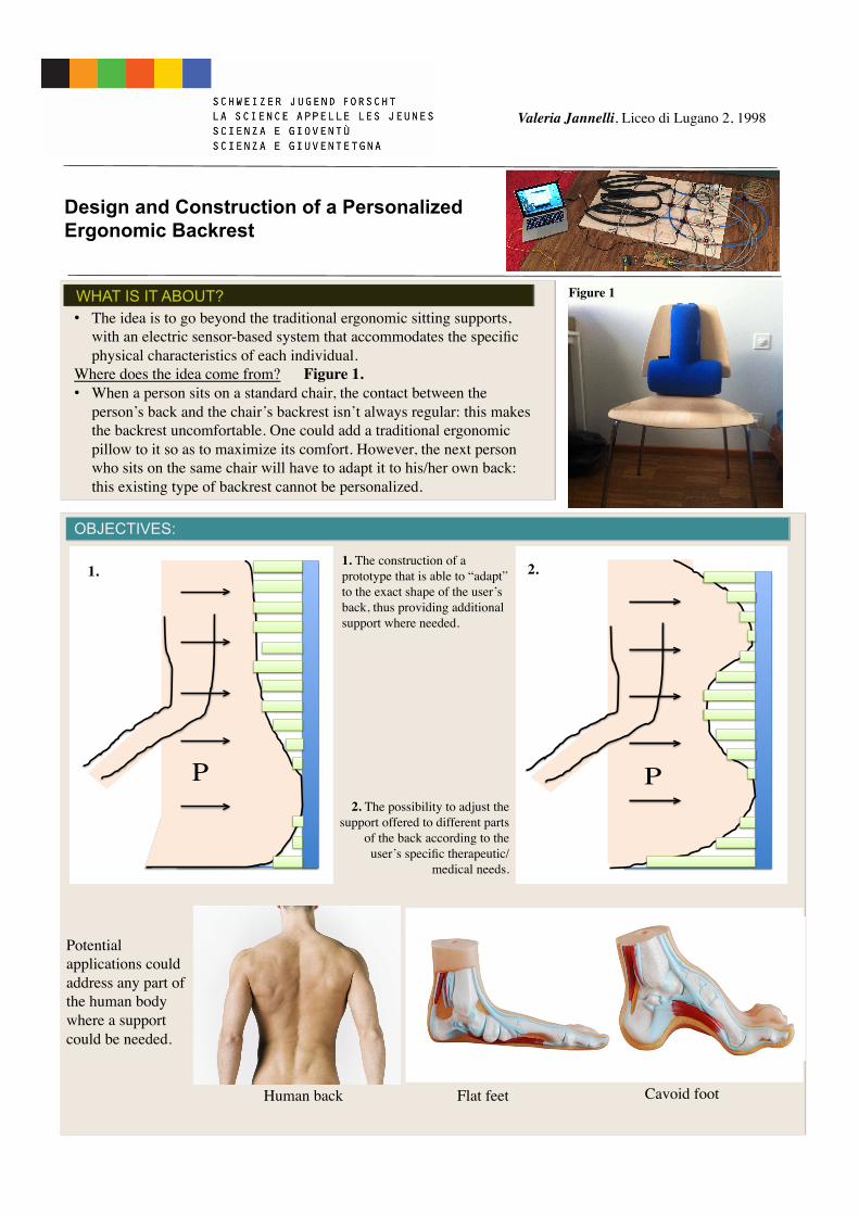
Where does the idea come from? Figure 1.• When a person sits on a standard chair, the contact between the
person’s back and the chair’s backrest isn’t always regular: this makes the backrest uncomfortable. One could add a traditional ergonomic pillow to it so as to maximize its comfort. However, the next person who sits on the same chair will have to adapt it to his/her own back: this existing type of backrest cannot be personalized.
WHAT IS IT ABOUT?
OBJECTIVES:
Figure 1
1. The construction of a prototype that is able to “adapt” to the exact shape of the user’s back, thus providing additional support where needed.
2. The possibility to adjust the support offered to different parts
of the back according to the user’s specific therapeutic/
medical needs.
P
2.
P
1.
Potential applications could address any part of the human body where a support could be needed.
Human back
Flat feet
Cavoid foot
The idea works: once the code is activated, the pump is turned on and inflates air in the different inner tubes. The sensors measure the pressure level of the inner tubes constantly. The electric valves open and close correspondingly.
RESULTS
• Each inner tube reaches an optimal pressure level for supporting a specific region of the individual’s back.
• Whilst this mechanism is automatic, one can manually direct the pump to provide for medically prescribed pressure levels.
For practical reasons, this prototype only includes three inner tubes. Obviously a larger number of tubes could provide a more accurate map of the various regions of the human back, whichDISCUSSION
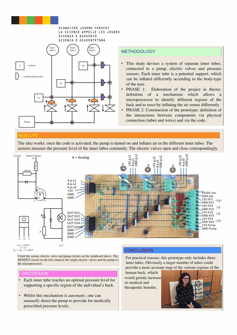
CONCLUSION I built the sensor, electric valve and pump circuits on the stripboard above. The MOSFET circuit on the left connects the single electric valves and the pump to the microprocessor.
would greatly increase its medical and therapeutic benefits.
METHODOLOGY
• This study devises a system of separate inner tubes, connected to a pump, electric valves and pressure sensors. Each inner tube is a potential support, which can be inflated differently according to the body-type of the user.
• PHASE 1: Elaboration of the project in theory; definition of a mechanism which allows a microprocessor to identify different regions of the back and to react by inflating the air rooms differently.
• PHASE 2: Construction of the prototype; definition of the interactions between components via physical connection (tubes and wires) and via the code.
!!
Pump!
S1!
S2!
S3!
Inner!tube!1!
Inner!tube!3!
Inner!tube!2!
S! =!sensor!
=!unidirectional!valve!
!
G!!!!!!!D!!!!!!!!S!
G! S!
D!
100!Ω!!
100!!Ω!!
!!!
!!" = 0.03!Ω!! = 2!!!
!!" = !!!" ∙ ! = 0.06!!!
!"##$%!!"#$%&'!!
!5!!!
!"#$%&!
12!!!
!
G!!!!!!!D!!!!!!!!S!
G! S!
D!
100!Ω!!
100!!Ω!!
!!!
!!" = 0.03!Ω!! = 2!!!
!!" = !!!" ∙ ! = 0.06!!!
!"##$%!!"#$%&'!!
!5!!!
!"#$%&!
12!!!
!
G!!!!!!!D!!!!!!!!S!G!
S! D!100!Ω!
!
100!!Ω!!
!! !
!!" =
0.03!Ω!!=
2!!!!!" =
!!!" ∙!=
0.06!!!
!"##$%!!"#$%&'!!5!!!
!"#$%&!
12!!!
A"p.s1"A"p.s2"A"p.s3"+5V"GND"GND"
A"="Analog"
OUT"EV1"OUT"EV2"OUT"EV3"OUT"EV4"OUT"pump"GND"GND"GND"
Switch"
NO N
ONO
+5V"p.s1"
A"p.s1"
GND"p.s1"
+5V"p.s2"
A"p.s2"
GND"p.s2"
+5V"p.s3"
A"p.s3"
GND"p.s3"
12VDC"ext."GND"ext."12V"EV1"GND"EV1"12V"EV2"GND"EV2"12V"EV3"GND"EV3"12V"EV4"GND"EV4"12V"Pump"GND"Pump"