design and construction of handheld metal...
TRANSCRIPT
DESIGN AND CONSTRUCTION
OF
HANDHELD METAL DETECTOR
BY
AROMOYE AKEEM OLUW AFEMI
2004/18792EE
DEPARTMENT OF ELECTRICAL AND COMPUTER ENGINEERING
SCHOOL OF ENGINEERING AND ENGINEERING
TECHNOLOGY
FEDERAL UNIVERSITY OF TECHNOLOGY, MINNA,
NIGER STATE, NIGERIA.
A PROJECT REPORT SUBMITTED IN A PARTIAL FULFILMENT OF
THE REQUIREMENT FOR THE AWARD OF BACHELOR OF
ENGINEERING DEGREE {B. ENGR.} IN ELECTRICAL AND
COMPUTER ENGINEERING
DECEMBER, 2009
ii
, - --~----~ -~ -~~~ ~~u.-__ """"""""o..l....Oioo.""""""--,,,,_,,,,,,,,,,"""'--"-"I"~ ... ~ '-.' .
. ' ~.'" t , { .
, i!t . ,
DECLARATION
I hereby declare that this project work was conducted by me under the supervision
of Engr. J. G. kolo, Electrical and Computer Engineering Department, Federal
University of Technology, Minna.
Aromoye Akeem Oluwafemi
--fJ J I h vvV»'-U.. ·······~·:~···········O··-;·· Student's signature
Engr. J. G. Kolo
~~ ...... ........-.-.-...... ................. .... .
Supervisor's signature
E gr. Dr. Y. A. Adediran
.. ~.~ . .l~ .. G.( ~ \.l Q ')
H. O. D's signature /
. ... . ....... . . .. . . . .... . .... ... ..... .. iii
External Examiner
. .I. ! . .fu.I./~TJ. t D ... ... . Date
••••• \ .1 • ./ •• f? r . .I. ?7?~. 0. ...
Date
Date
~A1.1(~ ........... . Date
DEDICATION
I dedicate this project to Almighty Allah for seeing me through this programme and also to my
lovely mother, Mrs. M. O. Aromoye for her moral and financial support through out my stay in
school.
iv

ACKNOWLEDGEMENT
I wish to express my sincere gratitude to my supervisor, Engr. J. G. Kolo for his moral
advice and intellectual support towards the completion of this project. Also, to the laboratory
technician, Mallam Umar.
My profound appreciation goes to Maolana Sheikh Ibrahim Nyass, Maolana Sheikh Nuru
Akeem, Alfa Salihu Oko-Olobi, Alhaji Ibrahim Isa Ladan, Alhaji Mohammed Isa Ladan for their
Spiritual and moral support.
To my family members, particularly my younger ones; Abdulrasheed , Saheed, Silifat.
To my friends in school; Sherif Baba, Ayan Baba, Morex Law, Sir Adams, Officer
Ayuba, Dare, Lateef physics, Azeez Mechanical, Wasiu Offa, Ganiyat Lawai (G-baby) and
others.
Finally, my sincere thanks to my dearest friends ; Mariam Ibrahim, Sherifat Mustapha,
Bola Bolaji, Ganiyat Mustapha, Helen.
v
ABSTRACT
Over the years, it has become an important issue to restrict the entry of people into
certain places with weapons or instruments of harm and destruction.
This project is a design and construction of an effective means of detecting dangerous
weapons made of metal in order to reduce crime rate in the society. It lIses the principle of
electromagnetic induction and adopts a digital beat frequency technique. The system uses a
search coil to detect metallic objects at a close range and gives a visual, auditory and vibratory
indication once the metallic object is detected. The search coil forms part of an LC oscillation
circuit. The operating frequency of the LC oscillator is primarily determined by the value of
involved inductor and capacitor. In case an inductance is altered, the frequency does not remain
the same by changing its value through the introduction of a metallic object.
vi
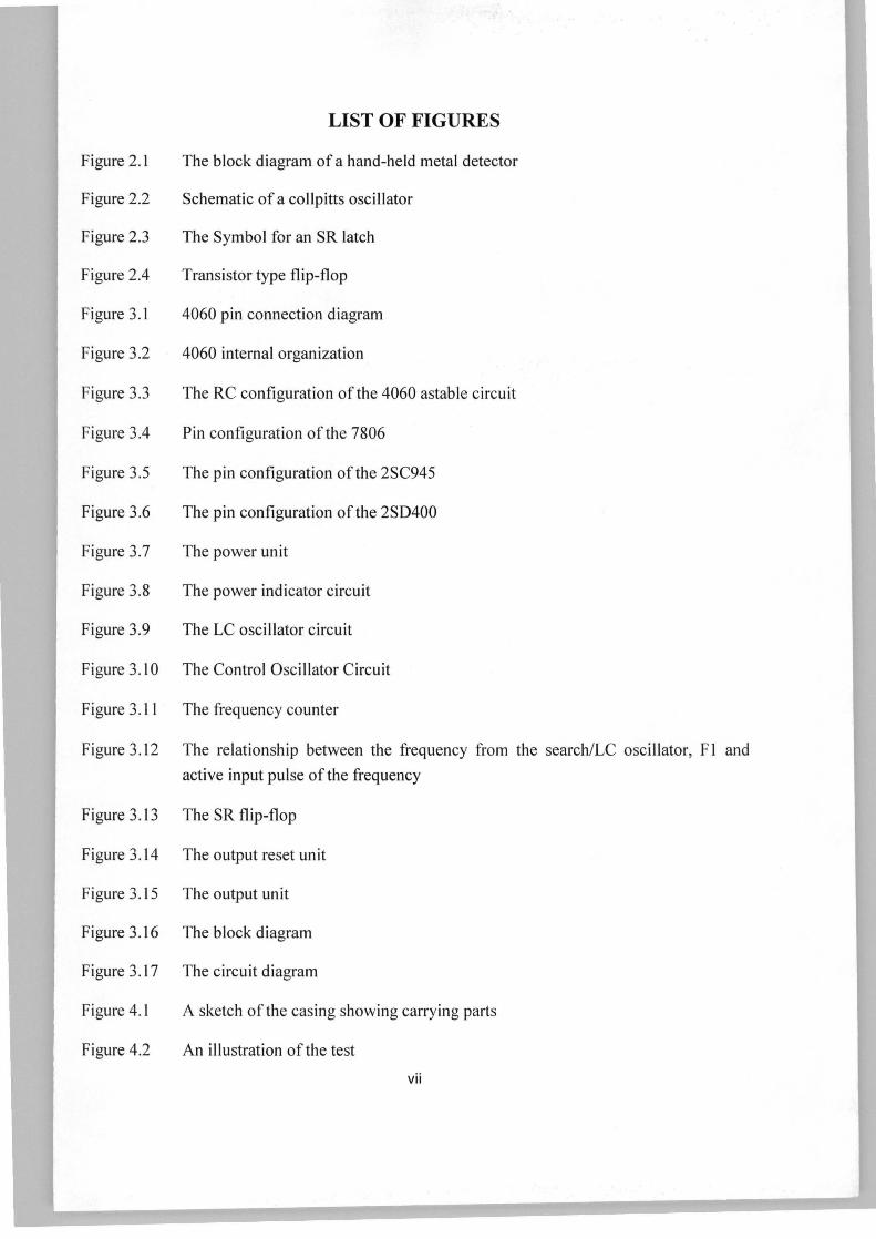
LIST OF FIGURES
Figure 2.1 The block diagram of a hand-held metal detector
Figure 2.2 Schematic of a collpitts oscillator
Figure 2.3 The Symbol for an SR latch
Figure 2.4 Transistor type flip-flop
Figure 3.1 4060 pin connection diagram
Figure 3.2 4060 internal organization
Figure 3.3 The RC configuration of the 4060 astable circuit
Figure 3.4 Pin configuration of the 7806
Figure 3.5 The pin configuration of the 2SC945
Figure 3.6 The pin configuration of the 2SD400
Figure 3.7 The power unit
Figure 3.8 The power indicator circuit
Figure 3.9 The LC oscillator circuit
Figure 3.10 The Control Oscillator Circuit
Figure 3.11 The frequency counter
Figure 3.12 The relationship between the frequency from the search/LC oscillator, F1 and
active input pulse ofthe freq uency
Figure 3.l3 The SR flip-flop
Figure 3.14 The output reset unit
Figure 3.15 The output unit
Figure 3.16 The block diagram
Figure 3.17 The circuit diagram
Figure 4.1 A sketch of the casing showing carrying parts
Figure 4.2 An illustration of the test
vii
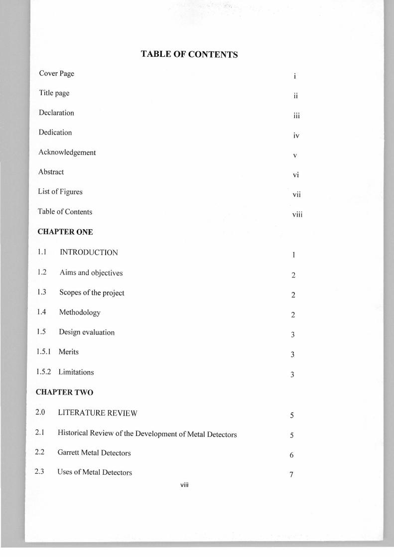
Cover Page
Title page
Declaration
Dedication
Acknowledgement
Abstract
List of Figures
Table of Contents
CHAPTER ONE
1.1 INTRODUCTION
1.2 Aims and objectives
1.3 Scopes of the project
1.4 Methodology
1.5 Design evaluation
1.5 .1 Merits
1.5 .2 Limitations
CHAPTER TWO
2.0 LITERA TURE REVIEW
TABLE OF CONTENTS
2.1 Historical Review of the Development of Metal Detectors
2.2 Garrett Metal Detectors
2.3 Uses of Metal Detectors
viii
II
III
iv
v
vi
VII
VIII
2
2
2
3
3
3
5
5
6
7
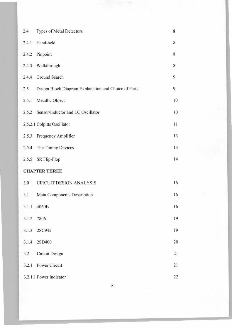
2.4 Types of Metal Detectors 8
2.4.1 Hand-held 8
2.4.2 Pinpoint 8
2.4.3 Walkthrough 8
2.4.4 Ground Search 9
2.5 Design Block Diagram Explanation and Choice of Parts 9
2.5.1 Metallic Object 10
2.5.2 Sensor/Inductor and LC Oscillator 10
2.5.2.1 Colpitts Oscillator 1 1
2.5 .3 Frequency Amplifier 13
2.5.4 The Timing Devices 13
2.5.5 SR Flip-Flop 14
CHAPTER THREE
3.0 CIRCUIT DESIGN ANALYSIS 16
3.1 Main Components Description 16
3.1.1 4060B 16
3.1.2 7806 19
3.1.3 2SC945 19
3.1.4 2SD400 20
3.2 Circuit Design 21
3.2.1 Power Circuit 21
3.2.1.1 Power Indicator 22
ix
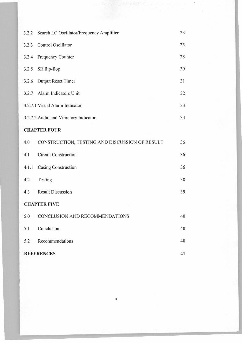
3.2.2 Search LC Oscillator/Frequency Amplifier 23
3.2.3 Control Oscillator 25
3.2.4 Frequency Counter 28
3.2.5 SR flip-flop 30
3.2.6 Output Reset Timer 31
3.2.7 Alarm Indicators Unit 32
3.2.7.1 Visual Alarm Indicator 33
3.2.7.2 Audio and Vibratory Indicators 33
CHAPTER FOUR
4.0 CONSTRUCTION, TESTING AND DISCUSSION OF RESULT 36
4.1 Circuit Construction 36
4.1.1 Casing Construction 36
4.2 Testing 38
4.3 Result Discussion 39
CHAPTER FIVE
5.0 CONCLUSION AND RECOMMENDATIONS
5.1 Conclusion
5.2 Recommendations
REFERENCES
x
40
40
40
41