design and control of a soft and continuously deformable ... · design and control of a soft and...
TRANSCRIPT
Design and Control of a Soft and Continuously Deformable 2D RoboticManipulation System*
Andrew D. Marchese1, Konrad Komorowski1, Cagdas D. Onal2, and Daniela Rus1
Abstract— In this paper we describe the design, fabrication,control, and experimental validation of a soft and highly compli-ant 2D manipulator. The arm consists of several body segmentsactuated using bi-directional fluidic elastomer actuators andis fabricated using a novel composite molding process. Weuse a cascaded PI and PID computation and novel fluidicdrive cylinders to provide closed-loop control of curvature foreach soft and highly compliant body segment. Furthermore, wedevelop algorithms to compute the arm’s forward and inversekinematics in a manner consistent with piece-wise constant cur-vature continuum manipulators. These computation and controlsystems enable this highly compliant robot to autonomouslyfollow trajectories. Experimental results with a robot consistingof six segments show that controlled movement of a soft andhighly compliant manipulator is feasible.
I. INTRODUCTION
Traditional rigid industrial robots provide optimal solu-tions for factory automation, where fast, precise, and con-trollable motions are utilized for repetitive tasks in struc-tured environments. However, in natural environments andhuman-centric operations where safety and adaptability touncertainty are fundamental requirements, soft robots mayserve as a better alternative to automation. Soft robots aredesigned with a continuously deformable backbone provid-ing theoretically infinite degrees of freedom; see reviewby Trivedi, Rahn, Kier, and Walker [1]. Soft robots canconform to variable but sensitive environments exemplifiedby Chen et al. [2]. They can adaptively manipulate andgrasp unknown objects varying in size and shape [3]. Andtheir high dexterity allows them to squeeze through confinedspaces [4]. However, a fundamental limitation in designingrobots to be softer and more compliant is that the robotsbecome increasingly unconstrained, making predictable andcontrolled movement difficult. Typically there is a balancebetween compliance and internal kinematic constraints thatmake controlled movement feasible.
In this work we demonstrate precise closed-loop positionalcontrol for a highly compliant planar continuum manipulatormade almost entirely of soft silicone rubber. The arm has theadvantage of being more compliant than most soft continuummanipulators, e.g. a force of only 1.5 N is required to hold
*This work was supported by the National Science Foundation, grantnumbers NSF IIS1226883 and NSF CCF1138967 as well as the NationalScience Foundation Graduate Research Fellowship Program, Primary Award1122374
1A. D. Marchese, K. Komorowski, and D. Rus are with the Com-puter Science and Artificial Intelligence Laboratory, Massachusetts In-stitute of Technology, Cambridge, MA 02139, USA andy, kkom,[email protected]
2C. D. Onal is with the Department of Mechanical Engineering, WorcesterPolytechnic Institute, Worcester, MA 01609, USA [email protected]
A
B
C
D
x
y
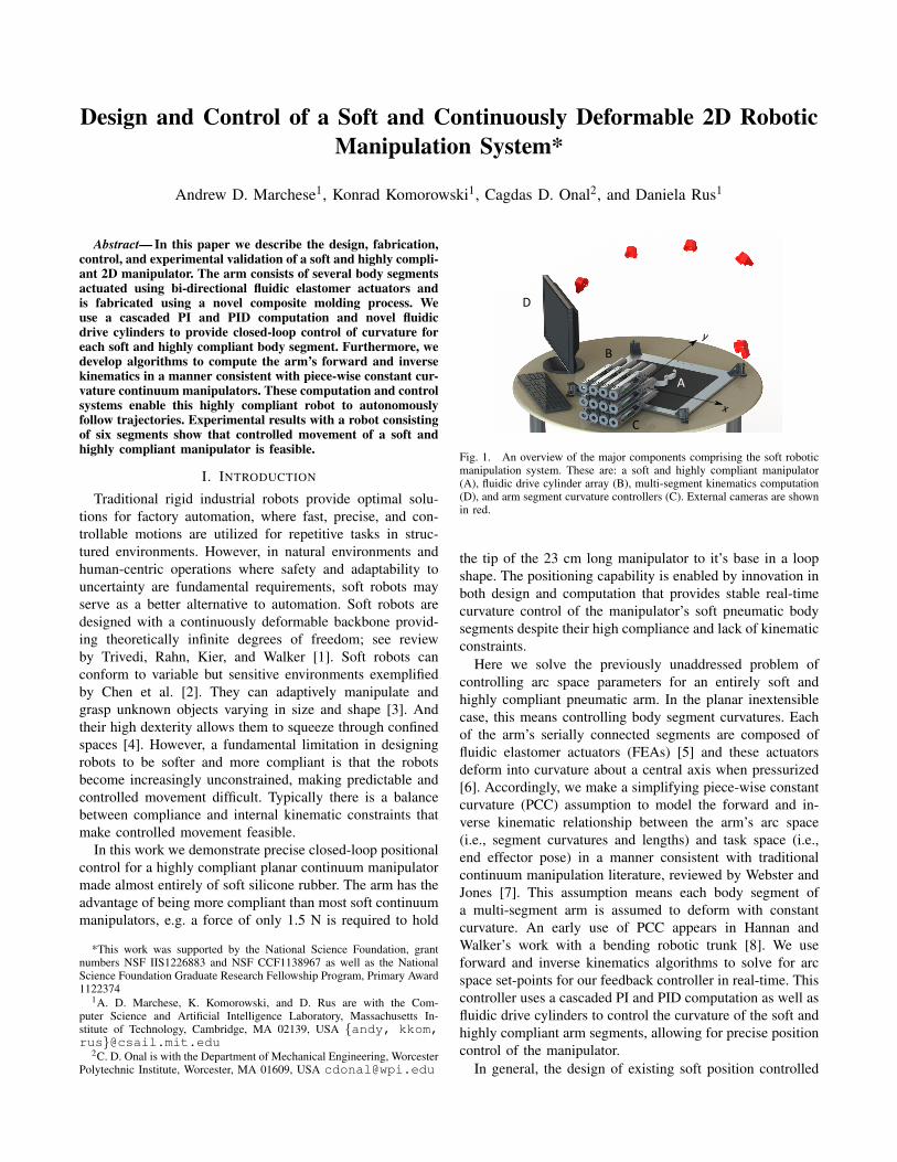
Fig. 1. An overview of the major components comprising the soft roboticmanipulation system. These are: a soft and highly compliant manipulator(A), fluidic drive cylinder array (B), multi-segment kinematics computation(D), and arm segment curvature controllers (C). External cameras are shownin red.
the tip of the 23 cm long manipulator to it’s base in a loopshape. The positioning capability is enabled by innovation inboth design and computation that provides stable real-timecurvature control of the manipulator’s soft pneumatic bodysegments despite their high compliance and lack of kinematicconstraints.
Here we solve the previously unaddressed problem ofcontrolling arc space parameters for an entirely soft andhighly compliant pneumatic arm. In the planar inextensiblecase, this means controlling body segment curvatures. Eachof the arm’s serially connected segments are composed offluidic elastomer actuators (FEAs) [5] and these actuatorsdeform into curvature about a central axis when pressurized[6]. Accordingly, we make a simplifying piece-wise constantcurvature (PCC) assumption to model the forward and in-verse kinematic relationship between the arm’s arc space(i.e., segment curvatures and lengths) and task space (i.e.,end effector pose) in a manner consistent with traditionalcontinuum manipulation literature, reviewed by Webster andJones [7]. This assumption means each body segment ofa multi-segment arm is assumed to deform with constantcurvature. An early use of PCC appears in Hannan andWalker’s work with a bending robotic trunk [8]. We useforward and inverse kinematics algorithms to solve for arcspace set-points for our feedback controller in real-time. Thiscontroller uses a cascaded PI and PID computation as well asfluidic drive cylinders to control the curvature of the soft andhighly compliant arm segments, allowing for precise positioncontrol of the manipulator.
In general, the design of existing soft position controlled
manipulators are not very soft. Originally, many hard hyperredundant and hard continuum robots [8] [9] [10] usedan array of servomotors or linear actuators to pull cablesthat moved rigid connecting plates located between bodysegments. Some soft robots have adopted a similar actuationscheme consisting of tendons pulling rigid fixtures embeddedon a continuously deformable backbone as seen in thesoft manipulators controlled by Gravagne and Walker [11],McMahan, Jones, and Walker [12], and Camarillo, Carlson,and Salisbury [13]. There is an example of a soft rubberposition controlled arm using cables without rigid platesby Wang et al. [14], but the arm consists of only oneactuated segment and therefore does not require internalfixtures. Another common design of position controlled softmanipulators involves distributed pneumatic muscle actuators(PMAs). Here, PMAs are embedded throughout the robot’sbody. Notable examples include OctArm IV [3] which uses18 air muscle actuators distributed throughout 4 arm seg-ments, the continuum manipulator developed by Pritts andRahn [15] which uses 14 McKibben actuators within twobody segments, and the manipulator developed by Kang,Branson, Zheng, Guglielmino, and Caldwell [16] which uses24 PMAs within 6 body segments. Again, these designsare not entirely soft but rather include rigid plates betweensegments for actuator mounting and kinematic constraint.
To the best of our knowledge, highly compliant robotswhose bodies are made from soft rubber and distributedpneumatic actuators are not capable of closed-loop curvaturecontrol. Prior works in this field use open-loop control, butthis approach is not sufficient for providing accurate controlof body segment curvature. Most fluid powered soft robotsuse open-loop valve sequencing (i.e., a valve is turned onfor a duration of time to pressurize the actuator and thenoff to either hold or deflate it) to control body segmentbending. For instance, there are soft rolling robots [5] [17][18] made of FEAs that use this control approach. Also asoft snake-like robot developed by Onal and Rus [19] usesthis open-loop scheme to control 8 distributed FEAs among4 body segments to enable serpentine locomotion. Again,Shepherd et al. use an open-loop valve controller to drivebody segment bending in an entirely soft multigait robot [4]and then passive control in an explosive, jumping robot [20].Martinez et al. [21] develop manually operated elastomertentacles containing 9 PneuNet actuators embedded within3 body segments. There is also an example of controlling asoft pneumatic inchworm-like robot using servo-controlledpressure described in [22]. Here, a PWM approach is usedto drive rapid valve switching to continuously vary airflow.
Open-loop control is also common for soft rubber robotsthat do not use pneumatic actuation. For example, previouswork on soft bioinspired octopus-like arms developed byCalisti et al. [23] demonstrate open-loop capabilities likegrasping and locomotion [24] [25]. Umedachi, Vikas, andTrimmer [26] developed a soft crawling robot that uses anopen-loop SMA driver to control body bending.
Our work differs from previous literature in both designand control. At a low level, we use a pair of position-
controlled linear fluidic drive cylinders to independentlypressurize the robot’s body actuators. This arrangement issuperior to solenoid valves since it enables precise analogcontrol of airflow into and out of body actuators. At a higherlevel, the feedback system controls the curvature of each ofthe robot’s body segments according to the arm’s modeledkinematics. This allows the system to autonomously controlthe pose of points along the arm. The contributions of thispaper include:• The design of a soft and highly compliant planar multi-
segment manipulator• The design of a novel drive system for soft fluidic
robots, the fluidic drive cylinder• Closed-loop curvature control for a soft and highly
compliant planar pneumatic robot• Autonomous position control of points along a multi-
segment soft and highly compliant continuum arm.
II. DESIGN
The soft robotic manipulation system is composed ofseveral subsystems. Figure 1 depicts the aggregate system,while highlighting the major subsystems: a soft and highlycompliant manipulator (A), fluidic drive cylinder array (B),multi-segment kinematics computation (D), arm segmentcurvature controllers (C).
A. Soft Arm
The soft and continuously deformable arm (Fig. 1A)functions as a manipulator and interacts with the environ-ment. In this work the manipulator’s reachable envelopeis constrained to the X-Y plane illustrated in Fig. 1. Byvolume, over 97 percent of the arm is composed of softsilicone rubber, excluding the feet. Structurally, the arm iscomposed of serially connected homogeneous elastomericbending segments. An individual segment is detailed in Fig.2. Each segment is fundamentally a fluidic elastomer actuator[5] [17] and capable of bending bi-directionally in the X-Yplane. Bending is the result of expansion and contractionof agonistic and antagonistic fluidic channel groupings (aand b) embedded within the segment’s elastomer (c). Chan-nel deformation is generated by pressurizing or vacuuminginternal fluid (d), which induces stress in the elastomer.An inextensible but continuously deformable constrainingfilm (e) separates agonistic and antagonistic fluidic channels.The constraint serves to transform channel deformation intosegment curvature by providing a neutral axis around whichthe segment bends. Fig. 2B depicts a segment in a stateof bending. Elongation of the agonistic channel groupingunder pressurization (red) causes the inextensible constraintto assume negative curvature. Contraction of the antagonisticchannel grouping under vacuum (cyan) allows for increasedbending, but is not required. Elastomer between channelspromotes channel deformation along the neutral axis andreduces extension along r, orthogonal to the neutral axis.
The soft arm, see Fig. 3, can be composed of any numberof segments (A). Markers are located at the interface between

a
b
c
d
e
A
B
x
y
r
Fig. 2. Cross section view of a soft arm segment depicting both a relaxed(A) and bent (B) state. Here, agonistic (a) and antagonistic (b) channelgroupings are embedded within silicone elastomer (c) and separated by aninextensible constraining layer (e). These channels house fluid (d) (yellow)which can be either pressurized (red) or vacuumed (cyan).
segments (D), making these points identifiable. The startingpoint of the arm’s first segment (B) is grounded to theplatform on which the arm moves. Ball transfers (C) are alsolocated at segment endpoints and enable the arm to move inthe two-dimensional plane with minimal friction. In manyexperiments conducted throughout this work the arm’s endeffector (E) is controlled.
A
B
C
D
E
Fig. 3. The soft arm is composed of homogeneous and independentlyactuated segments (A). The base of the arm’s first segment is fixed and theend of its last segment is the end effector (E). Markers (D) identify theendpoints of each segment and ball transfers (C) help the arm move withminimal friction.
B. Fluidic Drive Cylinders
In order to independently actuate arm segments, an arrayof custom fluidic drive cylinders (Fig. 1B) were devel-oped. These cylinders produce volumetric changes withinthe above mentioned embedded fluidic channels. Electriclinear actuators are directly coupled to and control the posi-tional displacement of pistons within the fluidic cylinders.Accordingly, these linear actuators govern the volumetricdisplacement of fluid out of the cylinders and into theembedded channels within the elastomeric arm segments, andvice versa.
An open loop, linear time-invariant dynamic model wascreated to approximate the performance of the fluidic drivecylinder. Although the model is not used in the control of
the cylinder because of its simplifications (in reality manyof these parameters are nonlinear), it served to identify theimpact design decisions have on input-output relationships.Fig. 4 shows a simplified schematic representation of thesystem and the parameters considered in developing themodel.
The equations of motion for the drive cylinder are writtenbelow. The piston’s linear motion is described as:
Fa−P2Ap = mpx2 (1)
Where Fa is the force exerted by the linear actuator on thepiston, P2 is the fluid pressure insider the cylinder, Ap andmp are the cross sectional area and the mass of the piston.Lastly, x2 is the piston displacement. The volumetric fluidflow into the elastomeric channels is approximated as:
P2−P1
Rt= (Ca +Cc) P1 (2)
Here, P1 is the fluid pressure within the channels of the armsegment. Rt is the resistance of the connecting tube. Ca andCc are the compliances of the elastomeric channels and fluidrespectively. The volumetric fluid flow into the cylinder isapproximated as:
Apx2 +P1−P2
Rt=CcP2 (3)
And lastly the force output of the linear actuator can beapproximated as:
Fa =−γ pRm
x2 +γ
Rmein (4)
Above, γ is a parameter relating force and motor currentin the linear actuator and p relates counter emf voltage tolinear velocity. Rm is the motor’s resistance, and ein is theinput motor voltage.
Fa
Ap
P2mp
x2
P1
Rt
Cc Ca
ein
Rm
Fig. 4. Parameters used in developing a simplified model of a fluidicdrive cylinder. At the left is a schematic representation of the electric linearactuator, at the middle is a representation of the piston and cylinder, and atthe right is a representation of an elastomeric channel grouping within anarm segment.
Using the aforementioned equations of motion, the openloop LTI system model can be written as Eqn. (5). Combin-ing Eqn. (1) and (4) yields the first row. The second row isEqn. (2), and the third row is Eqn. (3). Approximations ofthe model’s parameters are listed in Table I.x2
p1p2
=
−γ p
mpRm0 − Ap
mp
0 − 1(Cc+Ca)Rt
1(Cc+Ca)Rt
ApCc
1CcRt
− 1CcRt
x2
p1p2
+
γmpRm
00
ein (5)
Two drive cylinders are used to control a single bi-directional segment. Although the mapping of either the
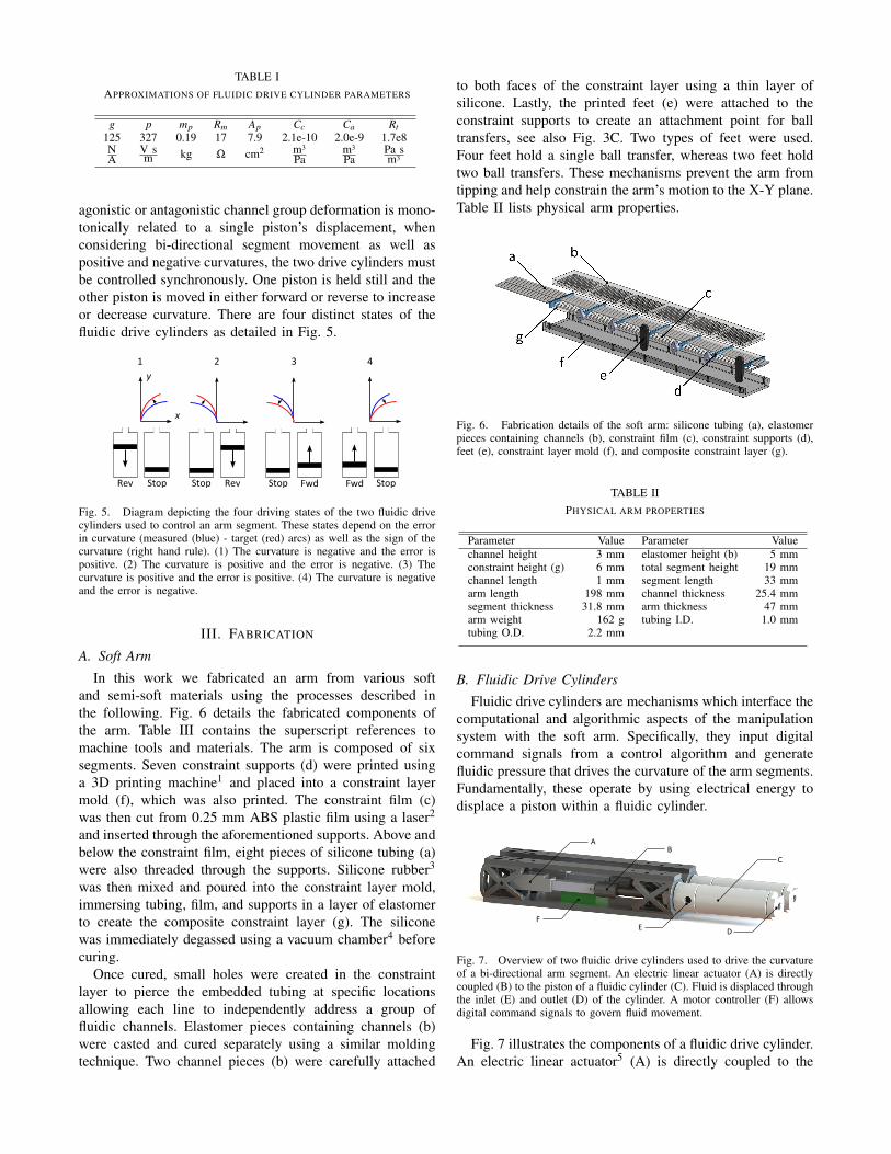
TABLE IAPPROXIMATIONS OF FLUIDIC DRIVE CYLINDER PARAMETERS
g p mp Rm Ap Cc Ca Rt125 327 0.19 17 7.9 2.1e-10 2.0e-9 1.7e8NA
V sm kg Ω cm2 m3
Pam3
PaPa sm3
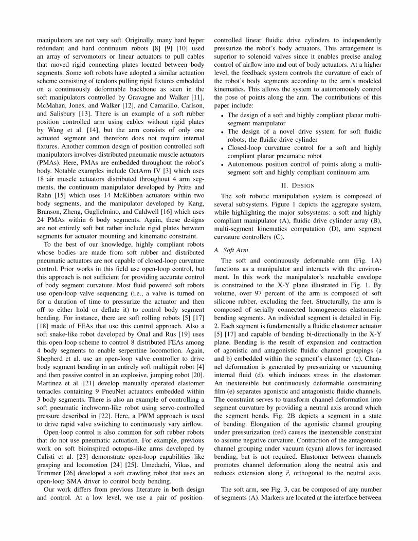
agonistic or antagonistic channel group deformation is mono-tonically related to a single piston’s displacement, whenconsidering bi-directional segment movement as well aspositive and negative curvatures, the two drive cylinders mustbe controlled synchronously. One piston is held still and theother piston is moved in either forward or reverse to increaseor decrease curvature. There are four distinct states of thefluidic drive cylinders as detailed in Fig. 5.
StopRev RevStop FwdStop StopFwd
x
y
1 2 3 4
Fig. 5. Diagram depicting the four driving states of the two fluidic drivecylinders used to control an arm segment. These states depend on the errorin curvature (measured (blue) - target (red) arcs) as well as the sign of thecurvature (right hand rule). (1) The curvature is negative and the error ispositive. (2) The curvature is positive and the error is negative. (3) Thecurvature is positive and the error is positive. (4) The curvature is negativeand the error is negative.
III. FABRICATION
A. Soft Arm
In this work we fabricated an arm from various softand semi-soft materials using the processes described inthe following. Fig. 6 details the fabricated components ofthe arm. Table III contains the superscript references tomachine tools and materials. The arm is composed of sixsegments. Seven constraint supports (d) were printed usinga 3D printing machine1 and placed into a constraint layermold (f), which was also printed. The constraint film (c)was then cut from 0.25 mm ABS plastic film using a laser2
and inserted through the aforementioned supports. Above andbelow the constraint film, eight pieces of silicone tubing (a)were also threaded through the supports. Silicone rubber3
was then mixed and poured into the constraint layer mold,immersing tubing, film, and supports in a layer of elastomerto create the composite constraint layer (g). The siliconewas immediately degassed using a vacuum chamber4 beforecuring.
Once cured, small holes were created in the constraintlayer to pierce the embedded tubing at specific locationsallowing each line to independently address a group offluidic channels. Elastomer pieces containing channels (b)were casted and cured separately using a similar moldingtechnique. Two channel pieces (b) were carefully attached
to both faces of the constraint layer using a thin layer ofsilicone. Lastly, the printed feet (e) were attached to theconstraint supports to create an attachment point for balltransfers, see also Fig. 3C. Two types of feet were used.Four feet hold a single ball transfer, whereas two feet holdtwo ball transfers. These mechanisms prevent the arm fromtipping and help constrain the arm’s motion to the X-Y plane.Table II lists physical arm properties.
Fig. 6. Fabrication details of the soft arm: silicone tubing (a), elastomerpieces containing channels (b), constraint film (c), constraint supports (d),feet (e), constraint layer mold (f), and composite constraint layer (g).
TABLE IIPHYSICAL ARM PROPERTIES
Parameter Value Parameter Valuechannel height 3 mm elastomer height (b) 5 mmconstraint height (g) 6 mm total segment height 19 mmchannel length 1 mm segment length 33 mmarm length 198 mm channel thickness 25.4 mmsegment thickness 31.8 mm arm thickness 47 mmarm weight 162 g tubing I.D. 1.0 mmtubing O.D. 2.2 mm
B. Fluidic Drive Cylinders
Fluidic drive cylinders are mechanisms which interface thecomputational and algorithmic aspects of the manipulationsystem with the soft arm. Specifically, they input digitalcommand signals from a control algorithm and generatefluidic pressure that drives the curvature of the arm segments.Fundamentally, these operate by using electrical energy todisplace a piston within a fluidic cylinder.
A
B
C
DE
F
Fig. 7. Overview of two fluidic drive cylinders used to drive the curvatureof a bi-directional arm segment. An electric linear actuator (A) is directlycoupled (B) to the piston of a fluidic cylinder (C). Fluid is displaced throughthe inlet (E) and outlet (D) of the cylinder. A motor controller (F) allowsdigital command signals to govern fluid movement.
Fig. 7 illustrates the components of a fluidic drive cylinder.An electric linear actuator5 (A) is directly coupled to the
piston of a fluidic cylinder6 (C) via a threaded coupler (B).The outlet of the cylinder (D) is connected to a single tube.The tube then connects to a channel grouping within thearm segment. The inlet (E) is open to ambient air. A motorcontroller7 (F) inputs digital commands from a controller andoutputs drive signals to the linear actuator.
TABLE IIICOMMERCIALLY AVAILABLE TOOLS AND EQUIPMENT
1 Fortus 400mc, Stratasys Ltd., Eden Prairie, MN2 VLS3.50, Universal Laser Systems, Inc., Scottsdale, AZ3 Ecoflex 0030, Smooth-On, Easton PA4 AL Cube, Abbess Instruments and Systems, Inc., Holliston, MA5 L16-50-35-12-P, Firgelli Technologies Inc., Victoria BC, Canada6 122-D, Bimba, University Park, IL7 1394, Pololu Corp., Las Vegas, NV8 Opti Track, NaturalPoint, Inc., Corvallis, OR
IV. CONTROLS
A. Curvature Estimation
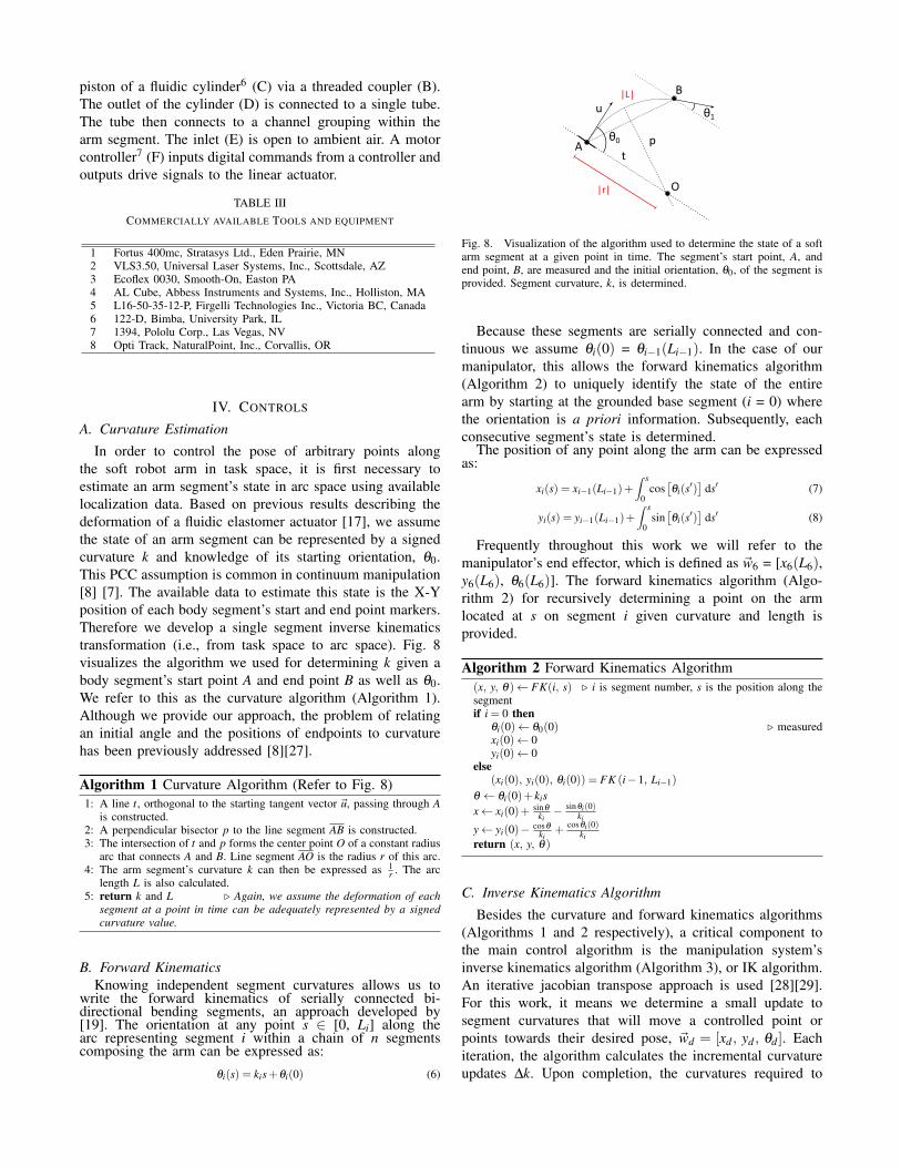
In order to control the pose of arbitrary points alongthe soft robot arm in task space, it is first necessary toestimate an arm segment’s state in arc space using availablelocalization data. Based on previous results describing thedeformation of a fluidic elastomer actuator [17], we assumethe state of an arm segment can be represented by a signedcurvature k and knowledge of its starting orientation, θ0.This PCC assumption is common in continuum manipulation[8] [7]. The available data to estimate this state is the X-Yposition of each body segment’s start and end point markers.Therefore we develop a single segment inverse kinematicstransformation (i.e., from task space to arc space). Fig. 8visualizes the algorithm we used for determining k given abody segment’s start point A and end point B as well as θ0.We refer to this as the curvature algorithm (Algorithm 1).Although we provide our approach, the problem of relatingan initial angle and the positions of endpoints to curvaturehas been previously addressed [8][27].
Algorithm 1 Curvature Algorithm (Refer to Fig. 8)1: A line t, orthogonal to the starting tangent vector u, passing through A
is constructed.2: A perpendicular bisector p to the line segment AB is constructed.3: The intersection of t and p forms the center point O of a constant radius
arc that connects A and B. Line segment AO is the radius r of this arc.4: The arm segment’s curvature k can then be expressed as 1
r . The arclength L is also calculated.
5: return k and L Again, we assume the deformation of eachsegment at a point in time can be adequately represented by a signedcurvature value.
B. Forward KinematicsKnowing independent segment curvatures allows us to
write the forward kinematics of serially connected bi-directional bending segments, an approach developed by[19]. The orientation at any point s ∈ [0, Li] along thearc representing segment i within a chain of n segmentscomposing the arm can be expressed as:
θi(s) = kis+θi(0) (6)
A
B
O
t
p
|r|
|L|
θ0
θ1u
Fig. 8. Visualization of the algorithm used to determine the state of a softarm segment at a given point in time. The segment’s start point, A, andend point, B, are measured and the initial orientation, θ0, of the segment isprovided. Segment curvature, k, is determined.
Because these segments are serially connected and con-tinuous we assume θi(0) = θi−1(Li−1). In the case of ourmanipulator, this allows the forward kinematics algorithm(Algorithm 2) to uniquely identify the state of the entirearm by starting at the grounded base segment (i = 0) wherethe orientation is a priori information. Subsequently, eachconsecutive segment’s state is determined.
The position of any point along the arm can be expressedas:
xi(s) = xi−1(Li−1)+∫ s
0cos
[θi(s′)
]ds′ (7)
yi(s) = yi−1(Li−1)+∫ s
0sin
[θi(s′)
]ds′ (8)
Frequently throughout this work we will refer to themanipulator’s end effector, which is defined as w6 = [x6(L6),y6(L6), θ6(L6)]. The forward kinematics algorithm (Algo-rithm 2) for recursively determining a point on the armlocated at s on segment i given curvature and length isprovided.
Algorithm 2 Forward Kinematics Algorithm(x, y, θ)← FK(i, s) i is segment number, s is the position along thesegmentif i = 0 then
θi(0)← θ0(0) measuredxi(0)← 0yi(0)← 0
else(xi(0), yi(0), θi(0)) = FK (i−1, Li−1)
θ ← θi(0)+ kisx← xi(0)+ sinθ
ki− sinθi(0)
ki
y← yi(0)− cosθki
+ cosθi(0)ki
return (x, y, θ)
C. Inverse Kinematics Algorithm
Besides the curvature and forward kinematics algorithms(Algorithms 1 and 2 respectively), a critical component tothe main control algorithm is the manipulation system’sinverse kinematics algorithm (Algorithm 3), or IK algorithm.An iterative jacobian transpose approach is used [28][29].For this work, it means we determine a small update tosegment curvatures that will move a controlled point orpoints towards their desired pose, wd = [xd , yd , θd ]. Eachiteration, the algorithm calculates the incremental curvatureupdates ∆k. Upon completion, the curvatures required to

attain the desired arm pose at that control time step arereturned. In other words, given the start and end points ofeach arm segment and θ0(0) as well as the desired pose(s),the algorithm determines a curvature discrepancy for eacharm segment.
Algorithm 3 Inverse Kinematics Algorithm1: Given: [wd ] desired pose(s)2: Retrieve start and end points of segments3: Calculate current arm state
(L, k, θ0(0)
)using Algorithm 1
4: for i = 0, i ≤ max iterations, i++ do5: [wc] ← FK(i, s) current pose(s)6: e ← [wd − wc] compute error in pose(s)7: J ← Calculate the current closed form Jacobian (9)8: ∆k ← αJT e α is the step size correction9: k ← k+ ∆k
We are able to write the jacobian in closed-form and this isfundamental to the inverse kinematics algorithm (Algorithm3).
J =∂ w
(L, k, θ0(0)
)∂ k
(9)
A current arm state can be easily substituted into 9 allowingthe IK algorithm to be run each iteration of the real-timecontroller.
D. Main Control Algorithm
The main control algorithm determines adjustments tosegment curvatures in real-time that are required to movea point or points along the arm through their requested posetrajectory. Before using the inverse kinematics algorithm(Algorithm 3), the main controller ensures the integrity ofmeasured data by comparing it to historical data. Oncethe required curvature updates are computed, this algorithmpasses the information to the lower level segment controllers.
E. Arm Segment Controller
In order to drive arm segment curvatures to their requiredvalues, a closed-loop arm segment control algorithm wasdeveloped. This low-level control algorithm periodically re-ceives discrepancies between the soft arm’s measured andrequested curvatures and uses a cascaded control structure toeffectively adjust fluidic drive cylinders and resolve the error.The controller achieves this by running a PI computationon the curvature error in order to generate a new set-pointfor the positional control of the linear actuator. Due tothe limitations of the used localization system8, this outerloop runs at a relatively slow rate (20 hz) and is initiatedwhen the main control algorithm (Section IV D) produces acurvature error. The inner loop, or positional PID controllerruns at 1 kHz to bring the cylinder’s piston displacementto the newly determined set-point. The cylinder’s pistondisplacement is the primary manipulated variable as fluidpressure is monotonically related to segment curvature. Fig. 9visualizes the cascaded control algorithm. Each of the arm’ssegments has its own controller.
Fig. 9. Cascaded control feedback algorithm used to set the soft arm’scurvatures. Each arm segment is controlled at a low-level by this nestedcurvature and positional controller. The inner loop runs substantial fasterthan the outer loop providing stable control over piston position.
V. EXPERIMENTS
The robotic manipulation system is able to accuratelyand precisely control the pose at points along the soft andcontinuously deformable arm in real-time. Specifically, themanipulation system can move the soft arm’s end effector toa user specified pose. We refer to this capability as point-to-point movement. The arm’s end effector can also tracktrajectories. Requested paths can be provided to the systemin real-time. We refer to this capability as path tracking. Inthis work we show how we are able to achieve these fun-damental capabilities while maintaining the most significantcharacteristic of this manipulation system, softness.
A. Single Segment Curvature Tracking
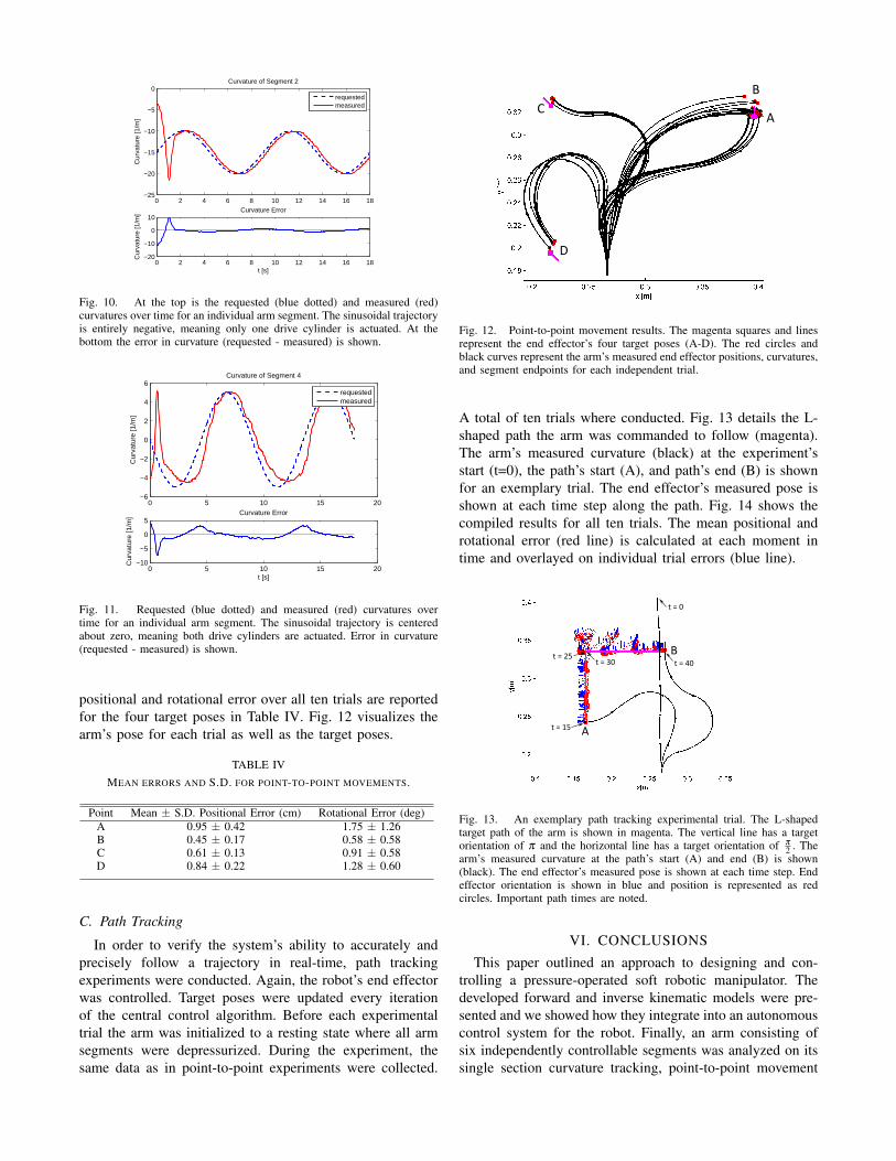
A fundamental result required for point-to-point movementand path tracking is the capability for an individual segmentto track a curvature profile varying over time. Fig. 10 detailsboth the target and measured curvature over time as well asthe error of the arm’s second segment. Here, the target profileis a sine wave of amplitude 5 1
m with a period of 9 seconds,centered about -15 1
m. A challenge for the controller istransitioning from driving either of the two fluidic cylindersto the other and this occurs when the segment’s curvaturepasses zero. Fig. 11 details curvature tracking of the arm’sfourth segment when a similar target sinusoidal profile iscentered about 0 1
m.
B. Point-to-Point Movements
In order to verify the system’s ability to accurately andprecisely control the pose of a point on the soft arm, point-to-point movement experiments were conducted. During theexperiment, the manipulator’s end effector was commandedto move to four reachable poses (see Fig. 12A-D). Beforemoving to one of the commanded poses, the arm wasinitialized to a resting state where all arm segments weredepressurized. The time history of each marker position aswell as the arm’s state
(k, L, θ0(0)
), as determined by the
curvature and forward kinematics algorithms, were logged.The arm was moved to each target pose ten consecutivetimes. After a settling period, the end effector’s error inpose was measured. The mean and standard deviation of the
0 2 4 6 8 10 12 14 16 18−25
−20
−15
−10
−5
0Curvature of Segment 2
Cur
vatu
re [1
/m]
requestedmeasured
0 2 4 6 8 10 12 14 16 18−20
−10
0
10
t [s]
Cur
vatu
re [1
/m]
Curvature Error
Fig. 10. At the top is the requested (blue dotted) and measured (red)curvatures over time for an individual arm segment. The sinusoidal trajectoryis entirely negative, meaning only one drive cylinder is actuated. At thebottom the error in curvature (requested - measured) is shown.
0 5 10 15 20−6
−4
−2
0
2
4
6Curvature of Segment 4
Cur
vatu
re [1
/m]
requestedmeasured
0 5 10 15 20−10
−5
0
5
t [s]
Cur
vatu
re [1
/m]
Curvature Error
Fig. 11. Requested (blue dotted) and measured (red) curvatures overtime for an individual arm segment. The sinusoidal trajectory is centeredabout zero, meaning both drive cylinders are actuated. Error in curvature(requested - measured) is shown.
positional and rotational error over all ten trials are reportedfor the four target poses in Table IV. Fig. 12 visualizes thearm’s pose for each trial as well as the target poses.
TABLE IVMEAN ERRORS AND S.D. FOR POINT-TO-POINT MOVEMENTS.
Point Mean ± S.D. Positional Error (cm) Rotational Error (deg)A 0.95 ± 0.42 1.75 ± 1.26B 0.45 ± 0.17 0.58 ± 0.58C 0.61 ± 0.13 0.91 ± 0.58D 0.84 ± 0.22 1.28 ± 0.60
C. Path Tracking
In order to verify the system’s ability to accurately andprecisely follow a trajectory in real-time, path trackingexperiments were conducted. Again, the robot’s end effectorwas controlled. Target poses were updated every iterationof the central control algorithm. Before each experimentaltrial the arm was initialized to a resting state where all armsegments were depressurized. During the experiment, thesame data as in point-to-point experiments were collected.
A
B
C
D
Fig. 12. Point-to-point movement results. The magenta squares and linesrepresent the end effector’s four target poses (A-D). The red circles andblack curves represent the arm’s measured end effector positions, curvatures,and segment endpoints for each independent trial.
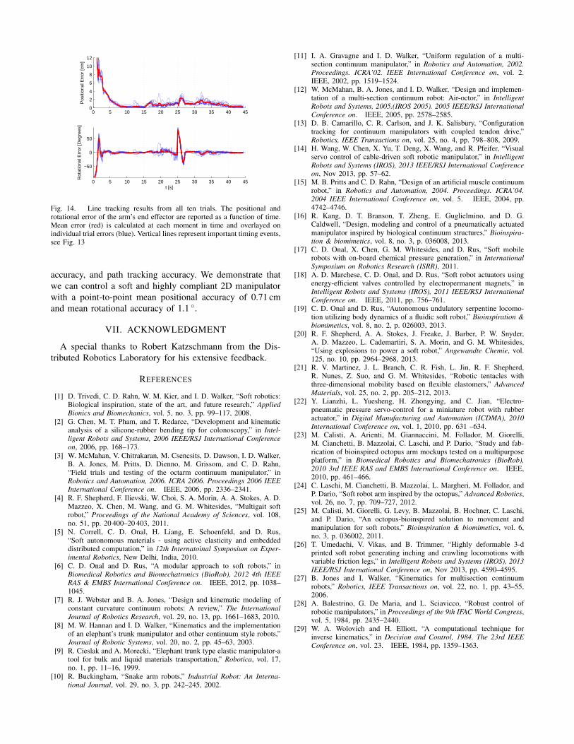
A total of ten trials where conducted. Fig. 13 details the L-shaped path the arm was commanded to follow (magenta).The arm’s measured curvature (black) at the experiment’sstart (t=0), the path’s start (A), and path’s end (B) is shownfor an exemplary trial. The end effector’s measured pose isshown at each time step along the path. Fig. 14 shows thecompiled results for all ten trials. The mean positional androtational error (red line) is calculated at each moment intime and overlayed on individual trial errors (blue line).
A
B
t = 15
t = 25t = 30 t = 40
t = 0
Fig. 13. An exemplary path tracking experimental trial. The L-shapedtarget path of the arm is shown in magenta. The vertical line has a targetorientation of π and the horizontal line has a target orientation of π
2 . Thearm’s measured curvature at the path’s start (A) and end (B) is shown(black). The end effector’s measured pose is shown at each time step. Endeffector orientation is shown in blue and position is represented as redcircles. Important path times are noted.
VI. CONCLUSIONS
This paper outlined an approach to designing and con-trolling a pressure-operated soft robotic manipulator. Thedeveloped forward and inverse kinematic models were pre-sented and we showed how they integrate into an autonomouscontrol system for the robot. Finally, an arm consisting ofsix independently controllable segments was analyzed on itssingle section curvature tracking, point-to-point movement
0 5 10 15 20 25 30 35 40 450
2
4
6
8
10
12
Pos
ition
al E
rror
[cm
]
0 5 10 15 20 25 30 35 40 45
−50
0
50
Rot
atio
nal E
rror
[Deg
rees
]
t [s]
Fig. 14. Line tracking results from all ten trials. The positional androtational error of the arm’s end effector are reported as a function of time.Mean error (red) is calculated at each moment in time and overlayed onindividual trial errors (blue). Vertical lines represent important timing events,see Fig. 13
accuracy, and path tracking accuracy. We demonstrate thatwe can control a soft and highly compliant 2D manipulatorwith a point-to-point mean positional accuracy of 0.71 cmand mean rotational accuracy of 1.1 .
VII. ACKNOWLEDGMENT
A special thanks to Robert Katzschmann from the Dis-tributed Robotics Laboratory for his extensive feedback.
REFERENCES
[1] D. Trivedi, C. D. Rahn, W. M. Kier, and I. D. Walker, “Soft robotics:Biological inspiration, state of the art, and future research,” AppliedBionics and Biomechanics, vol. 5, no. 3, pp. 99–117, 2008.
[2] G. Chen, M. T. Pham, and T. Redarce, “Development and kinematicanalysis of a silicone-rubber bending tip for colonoscopy,” in Intel-ligent Robots and Systems, 2006 IEEE/RSJ International Conferenceon, 2006, pp. 168–173.
[3] W. McMahan, V. Chitrakaran, M. Csencsits, D. Dawson, I. D. Walker,B. A. Jones, M. Pritts, D. Dienno, M. Grissom, and C. D. Rahn,“Field trials and testing of the octarm continuum manipulator,” inRobotics and Automation, 2006. ICRA 2006. Proceedings 2006 IEEEInternational Conference on. IEEE, 2006, pp. 2336–2341.
[4] R. F. Shepherd, F. Ilievski, W. Choi, S. A. Morin, A. A. Stokes, A. D.Mazzeo, X. Chen, M. Wang, and G. M. Whitesides, “Multigait softrobot,” Proceedings of the National Academy of Sciences, vol. 108,no. 51, pp. 20 400–20 403, 2011.
[5] N. Correll, C. D. Onal, H. Liang, E. Schoenfeld, and D. Rus,“Soft autonomous materials - using active elasticity and embeddeddistributed computation,” in 12th Internatoinal Symposium on Exper-imental Robotics, New Delhi, India, 2010.
[6] C. D. Onal and D. Rus, “A modular approach to soft robots,” inBiomedical Robotics and Biomechatronics (BioRob), 2012 4th IEEERAS & EMBS International Conference on. IEEE, 2012, pp. 1038–1045.
[7] R. J. Webster and B. A. Jones, “Design and kinematic modeling ofconstant curvature continuum robots: A review,” The InternationalJournal of Robotics Research, vol. 29, no. 13, pp. 1661–1683, 2010.
[8] M. W. Hannan and I. D. Walker, “Kinematics and the implementationof an elephant’s trunk manipulator and other continuum style robots,”Journal of Robotic Systems, vol. 20, no. 2, pp. 45–63, 2003.
[9] R. Cieslak and A. Morecki, “Elephant trunk type elastic manipulator-atool for bulk and liquid materials transportation,” Robotica, vol. 17,no. 1, pp. 11–16, 1999.
[10] R. Buckingham, “Snake arm robots,” Industrial Robot: An Interna-tional Journal, vol. 29, no. 3, pp. 242–245, 2002.
[11] I. A. Gravagne and I. D. Walker, “Uniform regulation of a multi-section continuum manipulator,” in Robotics and Automation, 2002.Proceedings. ICRA’02. IEEE International Conference on, vol. 2.IEEE, 2002, pp. 1519–1524.
[12] W. McMahan, B. A. Jones, and I. D. Walker, “Design and implemen-tation of a multi-section continuum robot: Air-octor,” in IntelligentRobots and Systems, 2005.(IROS 2005). 2005 IEEE/RSJ InternationalConference on. IEEE, 2005, pp. 2578–2585.
[13] D. B. Camarillo, C. R. Carlson, and J. K. Salisbury, “Configurationtracking for continuum manipulators with coupled tendon drive,”Robotics, IEEE Transactions on, vol. 25, no. 4, pp. 798–808, 2009.
[14] H. Wang, W. Chen, X. Yu, T. Deng, X. Wang, and R. Pfeifer, “Visualservo control of cable-driven soft robotic manipulator,” in IntelligentRobots and Systems (IROS), 2013 IEEE/RSJ International Conferenceon, Nov 2013, pp. 57–62.
[15] M. B. Pritts and C. D. Rahn, “Design of an artificial muscle continuumrobot,” in Robotics and Automation, 2004. Proceedings. ICRA’04.2004 IEEE International Conference on, vol. 5. IEEE, 2004, pp.4742–4746.
[16] R. Kang, D. T. Branson, T. Zheng, E. Guglielmino, and D. G.Caldwell, “Design, modeling and control of a pneumatically actuatedmanipulator inspired by biological continuum structures,” Bioinspira-tion & biomimetics, vol. 8, no. 3, p. 036008, 2013.
[17] C. D. Onal, X. Chen, G. M. Whitesides, and D. Rus, “Soft mobilerobots with on-board chemical pressure generation,” in InternationalSymposium on Robotics Research (ISRR), 2011.
[18] A. D. Marchese, C. D. Onal, and D. Rus, “Soft robot actuators usingenergy-efficient valves controlled by electropermanent magnets,” inIntelligent Robots and Systems (IROS), 2011 IEEE/RSJ InternationalConference on. IEEE, 2011, pp. 756–761.
[19] C. D. Onal and D. Rus, “Autonomous undulatory serpentine locomo-tion utilizing body dynamics of a fluidic soft robot,” Bioinspiration &biomimetics, vol. 8, no. 2, p. 026003, 2013.
[20] R. F. Shepherd, A. A. Stokes, J. Freake, J. Barber, P. W. Snyder,A. D. Mazzeo, L. Cademartiri, S. A. Morin, and G. M. Whitesides,“Using explosions to power a soft robot,” Angewandte Chemie, vol.125, no. 10, pp. 2964–2968, 2013.
[21] R. V. Martinez, J. L. Branch, C. R. Fish, L. Jin, R. F. Shepherd,R. Nunes, Z. Suo, and G. M. Whitesides, “Robotic tentacles withthree-dimensional mobility based on flexible elastomers,” AdvancedMaterials, vol. 25, no. 2, pp. 205–212, 2013.
[22] Y. Lianzhi, L. Yuesheng, H. Zhongying, and C. Jian, “Electro-pneumatic pressure servo-control for a miniature robot with rubberactuator,” in Digital Manufacturing and Automation (ICDMA), 2010International Conference on, vol. 1, 2010, pp. 631 –634.
[23] M. Calisti, A. Arienti, M. Giannaccini, M. Follador, M. Giorelli,M. Cianchetti, B. Mazzolai, C. Laschi, and P. Dario, “Study and fab-rication of bioinspired octopus arm mockups tested on a multipurposeplatform,” in Biomedical Robotics and Biomechatronics (BioRob),2010 3rd IEEE RAS and EMBS International Conference on. IEEE,2010, pp. 461–466.
[24] C. Laschi, M. Cianchetti, B. Mazzolai, L. Margheri, M. Follador, andP. Dario, “Soft robot arm inspired by the octopus,” Advanced Robotics,vol. 26, no. 7, pp. 709–727, 2012.
[25] M. Calisti, M. Giorelli, G. Levy, B. Mazzolai, B. Hochner, C. Laschi,and P. Dario, “An octopus-bioinspired solution to movement andmanipulation for soft robots,” Bioinspiration & biomimetics, vol. 6,no. 3, p. 036002, 2011.
[26] T. Umedachi, V. Vikas, and B. Trimmer, “Highly deformable 3-dprinted soft robot generating inching and crawling locomotions withvariable friction legs,” in Intelligent Robots and Systems (IROS), 2013IEEE/RSJ International Conference on, Nov 2013, pp. 4590–4595.
[27] B. Jones and I. Walker, “Kinematics for multisection continuumrobots,” Robotics, IEEE Transactions on, vol. 22, no. 1, pp. 43–55,2006.
[28] A. Balestrino, G. De Maria, and L. Sciavicco, “Robust control ofrobotic manipulators,” in Proceedings of the 9th IFAC World Congress,vol. 5, 1984, pp. 2435–2440.
[29] W. A. Wolovich and H. Elliott, “A computational technique forinverse kinematics,” in Decision and Control, 1984. The 23rd IEEEConference on, vol. 23. IEEE, 1984, pp. 1359–1363.