design and development of a model of wasted energy … · design and development of a model of...
TRANSCRIPT

Design and Development of A Model of Wasted EnergyHarvesting from Vibration and Backlash Wind as a Source
Chapter 1
1.1 INTRODUCTION:
Today every country draws its energy needs from a variety of
sources. These sources can be categorized as conventional and non-
conventional source of energy. The conventional sources are Fossil
Fuel Energy, Hydraulic Energy and Nuclear Energy. Out of these, the
fossil fuels are used to generate energy in more than 85% of all
energy sources. Hydraulic Energy system has got a high setup cost,
while Nuclear Energy involves a high risk. On the other hand, there
has been a rapid and massive depletion and exhaustion of fossil fuels
globally, for last few decades. Currently, there is hardly a stock of
around 100 years of fossil fuel at the present rate of turnover
(International Energy Annual 2006)[1].There are a number of wars,
massive economic and political instability on gaining control over the
fossil fuel reserve in the world.
Another important aspect in the area of energy conservation is
prevention and utilization of wastage of energy drawn from various
conventional and non conventional sources. During execution of the
activity of various machines, a part of energy is lost due to friction
and vibration and dissipated as unused heat. Systems have been
International Journal of Scientific & Engineering Research, (IJSER) ISSN 2229-5518 1
IJSER © 2013 http://www.ijser.org

developed to reduce these energy losses; however it cannot be
completely prevented.
These byproducts of machine operations can be suitably used to
generate power.
Energy harvesting stands for recovering energy wasted in a
process and to store and reuse that energy in another process.
In the present project, we intend to utilize the vibration and wind
backlash generated during locomotives operation as a means of
energy harvest and to use them as a source to carry out other
purposeful activities. We have aimed to develop an alternate source of
energy instrument. The source is fed with the unused energy produced
due to locomotive movements such as noise, heat, backlash wind and
vibrations and produces a controlled electric power.
1.2 OBJECTIVES:
The objective of this project can be divided in two parts as listed
below,
To derive the generalized equation for electromagnetic
induction generator using vibration as a source and small scale
wind turbine generator uses backlash wind of a locomotive as a
source.
International Journal of Scientific & Engineering Research, (IJSER) ISSN 2229-5518 2
IJSER © 2013 http://www.ijser.org

To design an induction generator and small scale wind turbine
such that they can be used as a voltage source with good power
rating.
1.3 MOTIVATION OF THE PRESENT PROJECT:
Among various forms and types of non conventional energy
system, the entities which reasonably attracted maximum attention to
the academia and the industry are solar energy, wind energy, tidal
energy, biomass fuel system etc. However, relatively lesser emphasis
has been poised on the form of energy harvesting utilizing mechanical
vibration and backlash wind produced during operation of the
machines; as a source.
In view of the potential role of vibration and backlash wind
produced in a moving automobile or a locomotive in generating
power, which can be appropriately stored and used; it will be highly
prudent to explore this area of non-conventional energy sources.
1.4 LITERATURE REVIEW AND PRESENT STATE OF
KNOWLEDGE:
1.4.1 Vibration power generator
The field of energy harvesting has become increasingly
important in recent years. There are numerous situations when ‘lost
energy’ (e.g. kinetic energy, present in the form of vibrations, random
displacements or force) converted into ‘usable energy’ (e.g. electrical
International Journal of Scientific & Engineering Research, (IJSER) ISSN 2229-5518 3
IJSER © 2013 http://www.ijser.org

energy) could be used to power devices with requirements ranging
from large to small-scale power generators.
The main transduction mechanisms used to extract energy from
the system and to implement a vibration power generator are:
electromagnetic, piezoelectric, magnetostrictive and electrostatic.
The electromagnetic mechanism employs electromagnetic
induction arising from the relative motion of the magnetic flux
gradient and a conductor (the Faraday’s law). According to the
fundamentals of electromagnetism, it is known that the electromotive
force induced in a circuit is linked to the product of the flux linkage
gradient and the velocity. The flux linkage gradient is dependent on
the magnets used to produce the field, the arrangement of these
magnets and the area and number of turns for the coil. The majority of
recent developments of devices using electromagnetic energy
conversion is focused on generators with microwatt or milliwatt
power levels of vibration frequency of the order of hundreds of hertz
and amplitudes of the order of micrometer. These generators are used
first of all in applications for wireless monitoring and automation.
In the last decade many articles have been published on the
topic of generators using electromagnetic, piezoelectric,
magnetostrictive and electrostatic energy conversion mechanisms. For
example, El-Hami et al (2001) [2] showed the electromechanical
power generator was capable of generating energy of about of 0.5
mW for a vibration amplitude of tens of micrometer and a frequency
of hundreds of hertz. (Beeby et al 2005) [3,4] reported the design,
International Journal of Scientific & Engineering Research, (IJSER) ISSN 2229-5518 4
IJSER © 2013 http://www.ijser.org

fabrication and performance testing of a micro-machined generator.
Glynne-Jones et al (2004) [5] demonstrated that the micro-generator
used in car engine compartments was capable of producing a 100 μW
level of power. Waters et al (2008) [6] showed the design and
applicability of a generator to a MEMS-scale device. Anton and
Sodano (2007) [7] discussed the research works in the area of power
harvesting with piezoelectric materials and goals which had to be
achieved so that self-powered devices could be used on an everyday
basis. Roundy and Wright (2004) [8] described the modeling and
design of a piezoelectric vibration-to-electricity converter to be used
as a power source for wireless electronics.
Priya (2007) [9,10] presented comprehensive coverage of the
recent developments in the area of piezoelectric energy harvesting
using low profile transducers and the results for various energy
harvesting prototype devices. Wang and Yuan (2007, 2008) [11]
reported the design, development and testing of a micro-vibration
generator based on a magnetostrictive material (Metglas 2605SC)
used in building practical energy harvesting wireless sensor networks.
Roundy et al (2002) presented the electrostatic generator fabricated
and tested using silicon MEMS technology as a power source for
wireless sensor nodes. Despesse et al (2005) [12] described an
electrostatic micro-device with high electrical damping designed for
vibration energy harvesting to operate over a wide frequency range
<100 Hz. Lee et al (2009) [13] compared the capabilities of different
electrostatic mechanisms for energy harvesting and discussed the
International Journal of Scientific & Engineering Research, (IJSER) ISSN 2229-5518 5
IJSER © 2013 http://www.ijser.org

relations among the contributing parameters involved in maximizing
the energy output that can be harvested from an electrostatic MEMS
device.
A comprehensive review of the state-of-the-art in vibration
energy harvesting for wireless, self-powered systems is presented by
Beeby et al (2006)[3,4]. Their article describes energy harvesting
systems based upon electromagnetic, piezoelectric and electrostatic
technologies, and provides the main characteristics for generators
using these technologies. An excellent overview of fundamentals,
current developments and prominent applications in the field of
energy harvesting is provided by Priya and Inman (2009)[9,10]. This
book presents the current state of knowledge and achievements of
leading researchers both in academia and industry.
Alongside a growing number of publications on energy
harvesting strategies, several new applications have been designed.
There are also industries which specialize in the research,
development, manufacturing and assembly of converting ‘lost energy’
into ‘usable energy’ and work with unique power solutions which
employ electromagnetic or piezoelectric transduction mechanisms to
generate electrical energy from motion. The electromagnetic
mechanism of electrical power generation has been used in generators
for many years.
The electromagnetic generators used today for large-scale
applications are based on rotations, while for applications with
International Journal of Scientific & Engineering Research, (IJSER) ISSN 2229-5518 6
IJSER © 2013 http://www.ijser.org

microwatt or milliwatt levels of power they use both rotational and
linear devices.
Several articles have been published about electromagnetic
power generators and the MR damper. Cho et al (2005) [4]described a
conceptual design of the electromagnetic generator in self-powered
MR damper based vibration reduction systems and proposed its
application for large-scale civil structures.
Also Cho et al (2007) [14] demonstrated the structure of the
electromagnetic generator to be used with the MR damper and some
test results. Choi et al (2009)[15] reported a similar concept of the
generator for the electro rheological (ER) damper in a vibration
control system of a vehicle suspension. In this system the ER damper
was completed with a rack and pinion mechanism converting a linear
motion into rotary motion.
However, not many reports are being published regarding
vibration power generator in automobile and locomotives.
1.4.2Wind turbine power generator:
Wind power has been harnessed as a source of power around the
world for a long time.
Wind is air in motion, caused by the uneven heating of the Earth
by the sun. Wind occurs when warm air rises, and cooler air moves in
to fill the space. It is estimated that 2% of the solar energy reaching
the earth is converted into wind energy. Air is constantly being
International Journal of Scientific & Engineering Research, (IJSER) ISSN 2229-5518 7
IJSER © 2013 http://www.ijser.org

interchanged between the warm tropics and the cold polar caps. The
rotation of the Earth also produces wind.
The sun radiates the most heat over the equator and therefore the
air there is warmer. Air from both hemispheres is constantly moving
toward the equator. The rotation of the Earth causes the cool winds to
be deflected from east to west. As the surface of the earth heats and
cools unevenly, pressure zones are created that make air move from
high pressure to low pressure areas.
Wind energy: The process by which the kinetic energy of wind
is used to generate mechanical power or electrical energy is known as
wind power or wind energy. Kinetic means being related to or
produced by motion such as the blowing wind.
A windmill converts the force of the wind into turning force
acting on the rotor blades. The strength of this turning force is known
as torque.
History of Wind Power: Wind has been used for centuries to
propel ships and the wind routes were well known and used by
explorers such as Magellan and Columbus. Wind power was used as a
source of mechanical energy on land for thousands of years. The
Babylonians constructed windmills for irrigation as early as 1700 BC
and Europeans were using windmills by 1000 AD.
Wind speed and energy: The amount of energy that can be
captured from the wind is exponentially proportional to the speed of
the wind. If a windmill were perfectly efficient, the power generated
is approximately equal to:
International Journal of Scientific & Engineering Research, (IJSER) ISSN 2229-5518 8
IJSER © 2013 http://www.ijser.org

P (watts) = 1/2 D (air density) x A (area of rotor) x V cube (wind
velocity)
Therefore, if wind speed is doubled, the power in the wind increases
by a factor of eight, i.e. 2 x 2 x 2. In reality, because wind turbines are
not perfectly efficient, changes in wind velocity do not have such a
dramatic effect on wind power.
Wind Turbine Rotor Design: There has been a great deal of research
on rotor design including whether the turbine will be upwind (rotor
facing the wind) or downwind (rotor on the lee side), the number, size
and shape of blades, the load (forces acting on the rotor) and other
rotor aerodynamic considerations. Generally speaking, larger
windmill rotors and higher wind speed produce more power.
Most wind turbines are the classic Danish three-bladed design
with the rotor positioned up-wind (facing the wind). Even numbers of
blades cause instability. Some designs are two bladed, saving the cost
of a blade and reducing rotor weight. They need higher rotational
speeds to produce the same amount of power as a three bladed design.
These speeds produce more noise. There are one bladed designs that
require a counter-balance on the other side of the hub. They also
require higher rotational speed.
Aerodynamics of Rotors: Rotor blades act like airfoils. An
airfoil is a structure around which air flows creating lift. Rotor blades
have a special shape so that when the wind passes over them, it moves
faster over one side. Bernoulli's Principle states that increased air
velocity produces decreased pressure.
International Journal of Scientific & Engineering Research, (IJSER) ISSN 2229-5518 9
IJSER © 2013 http://www.ijser.org

When the wind blows there is a pocket of low pressure formed
on the downwind side of the blade. The blade is pulled toward the low
pressure making the rotor turn. This is called lift. The lift force is
stronger than the force, known as drag, acting on the front side of the
blade. The combination of lift and drag causes the rotor to spin like a
propeller, and the turning shaft spins a generator to make electricity.
In wind turbine design, the objective is to have a high lift-to-drag
ratio. This is accomplished by twisting the blades. The blades are
twisted so that the wind hits them at the correct angle of attack. This
twist is known a pitch.
In the last decade many articles have been published on the
topic of wind turbine. On January 2001 Muljadi and Butterfield
proposed a paper on operation of variable-speed wind turbines with
pitch control [16]. The system the authors considered is controlled to
generate maximum energy while minimizing loads. In this paper they
show that by pitch control and generator load control, the wind
turbine can be operated at its optimum energy capture while
minimizing the load and thus extending the range for wind speed.
Slootweg et al published a paper (2001) [17]where they
discussed on a wind turbine concept where the rotor speed , pitch
angle all can be controlled . This model is simulated and studied.
Nichita et al proposed (2002)[16] two modeling procedures for wind
speed simulation. Miller et al propose (2003) [18] a new model for
high power turbine where they described the modeling of a 3.5 M.W.
turbine. Tapia et al [19] modeled a simulation of a grid-connected
International Journal of Scientific & Engineering Research, (IJSER) ISSN 2229-5518 10
IJSER © 2013 http://www.ijser.org

wind driven doubly fed induction machine (DFIM) together with
some real machine performance results.
Researches are conducted on optimization and control
strategy of a wind turbine. Tan and Islam proposed (2004) [20] a
prototype version of the control strategy of a 20-kW permanent-
magnet synchronous generator (PMSG) for maximum power
tracking and compares with the results produced by previous
strategies and demonstrate its advantage over the existing ones.
Also Quincy Wang and Liuechen Chang developed another
algorithm (2004) [21] for obtaining maximum power from wind
turbine. Yazhou Lei et al discussed on variable speed wind turbine
using a doubly fed induction generator to increase the efficiency
of the turbine (2006) [22]. Liserre et al performed a study in 2006
[23] on photovoltaic solar cells and wind turbine grid inverters
for long term stability. Xingjia Yao et al (2007) [24] presented a
study on the performance of Doubly-fed Induction generator
based Wind Turbine.
International Journal of Scientific & Engineering Research, (IJSER) ISSN 2229-5518 11
IJSER © 2013 http://www.ijser.org
Chapter 2
Vibration power generator
2.1 Theoretical Background
The field of energy harvesting is a very important field in recent
year’s research. There are numerous researchers trying to convert the
‘lost energy’ (e.g. kinetic energy, present in the form of vibrations,
displacements or force) into ‘usable energy’ (e.g. electrical energy
which could be used to power devices).
The main target is to extract energy from the system by using a
vibration power generator. Those which are mostly in use are
piezoelectric, magnetostrictive, electrostatic and electromagnetic.
The principle of piezoelectric energy conversion is that some
piezoelectric materials become electrically polarized when subjected
to mechanical strain. The degree of polarization is proportional to the
applied strain. This property is used to direct the conversion of
vibrations into a voltage output by using a piezoelectric material.
Some magnetostrictive materials offer an even better capability
with regard to energy harvesting compared to piezoelectric materials.
International Journal of Scientific & Engineering Research, (IJSER) ISSN 2229-5518 12
IJSER © 2013 http://www.ijser.org

The advantages are ultra-high energy conversion efficiency and high
power density.
The basis of electrostatic energy convertor is the variable
capacitor. A variable capacitance structure is driven by mechanical
vibrations and oscillates between a maximum and a minimum
capacitance. If the charge on the capacitor is constrained, the voltage
will increase as the capacitance decreases. If the voltage across the
capacitor is constrained, charges will move from the capacitor to a
storage device or to the load as the capacitance decreases. In either
case, mechanical kinetic energy is converted to electrical energy.
The electromagnetic mechanism employs electromagnetic
induction arising from the relative motion of the magnetic flux
gradient and a conductor (the Faraday’s law). According to the
fundamentals of electromagnetism “The induced electromotive force
(EMF) in any closed circuit is equal to the time rate of change of the
magnetic flux through the circuit”. So the main principle here is to let
a magnet to move freely within a coil by using the force of vibration.
As the magnet moves within the coil it causes a change in flux
through the coil and according to Faraday’s law this will generate a
voltage in the coil.
The majority of recent developments of devices for converting
vibration into voltage are focused in Piezoelectric and
electromagnetic energy conversion generators.
In the present project, we have used the design of electromagnetic
energy conversion generators.
International Journal of Scientific & Engineering Research, (IJSER) ISSN 2229-5518 13
IJSER © 2013 http://www.ijser.org

2.2 Structure of the generator
The structure of the electromagnetic generator is symmetrical. A
theoretical block diagram of it is shown in figure 2.1. The structure
consists 6 Alinico bar Magnet circling a copper coil at equal distance
within a cylindrical Aluminium housing.
Fig. 2.1 Inner Diagram Of The induction generator
The magnets are arranged such that there North poles are
upward and South Pole is down ward. The coil is in between
supported along an axis by 6 springs thus it can move freely.
2.3 Design and dimension of the Induction generator:
The generator is constructed using an alluminium sheet with
dimension 160 x 160 x 3 mm. The system consists 6 Alinico bar
magnet surrounding a coil with equal distance. To prepare this system
International Journal of Scientific & Engineering Research, (IJSER) ISSN 2229-5518 14
IJSER © 2013 http://www.ijser.org
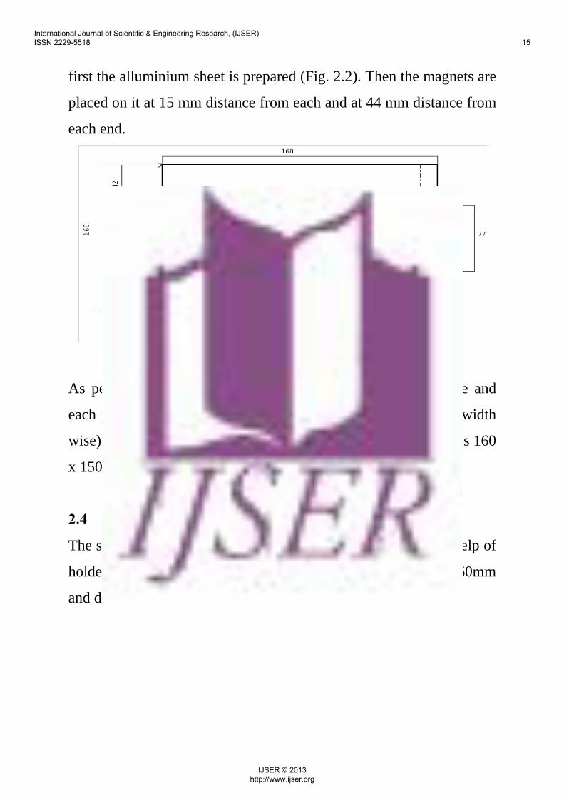
first the alluminium sheet is prepared (Fig. 2.2). Then the magnets are
placed on it at 15 mm distance from each and at 44 mm distance from
each end.
Fig. 2.2 Design and dimension of the Induction generator
As per as the design each magnet acquires 10 mm width wise and
each placed 15 mm apart. The last 10 mm space of the sheet (width
wise) is left for riveting purpose, which makes the useful space as 160
x 150 mm.
2.4 Final Diagram of the induction generator:
The sheet, after planting the magnets and fixing them with the help of
holders is bend and shaped as a cylinder (Fig 2) with height 160mm
and diameter 48 mm.
International Journal of Scientific & Engineering Research, (IJSER) ISSN 2229-5518 15
IJSER © 2013 http://www.ijser.org

Fig 2.3 Final Diagram of the induction generator
The system works on the principle of linear magnetic induction,
on Faraday’s Law of electro magnetism. Which is “The induced
electromotive force (EMF) in any closed circuit is equal to the time
rate of change of the magnetic flux through the circuit.”
Fig 2.4 Photograph of the generator
2.5 EQUATION GOVERNING THE BEHAVIOR OF THE
GENERATOR:
International Journal of Scientific & Engineering Research, (IJSER) ISSN 2229-5518 16
IJSER © 2013 http://www.ijser.org

E=-n ∂Ф / ∂t Assuming B as the flux density and A as the area of the
coil we have,
Ф = ∫ ⋅ dAB hence E=-n∂/ ∂t ∫ ⋅ dAB
2.6 WORKING OF THE GENERATOR:
Fig 2.5 Block Diagram of the Induction generator
The Vibration gives an upward thrust to the generator.
The coil systems move upward while the magnet remains fixed.
As the coil reaches its maximum height it comes down by its
own weight.
2.7 Formulation
International Journal of Scientific & Engineering Research, (IJSER) ISSN 2229-5518 17
IJSER © 2013 http://www.ijser.org

This structure is based on Faraday’s Law of electro magnetism.
The magnet-system produces a magnetic field of flux density B in the
coil. As the magnet system move along the axis it induces an electric
field in the coil around it. Which is E=-N ∂ Ф / ∂t. where Ф is the flux
in weber.
Assuming l is the length of the coil. ∂x is the distance the coil moves
after each thrust and ∂t is the time taken to reach ∂x (Assumed to be 1
since the distance is very small)
Fig 2.6 basic principle of induction generator working
∂x= (F-Mg)/2M [where M is the total mass of the generator, F is the
upward thrust by vibration]
Using Faraday’s Law we have
E=-N∂q/ ∂t [Taking ∂t as 1 that is calculating for unit time]
E=-N∂q
E=-NФ lv* ∂x [L is the length of the coil, V is velocity of the
magnet and ∂x is the distance travelled]
E=-NФ lv(F-Mg)/2M
E=-NФ l((F-Mg)/M)2/2
E=-NФ l(a/M)2/2 [a=(F-Mg)]
International Journal of Scientific & Engineering Research, (IJSER) ISSN 2229-5518 18
IJSER © 2013 http://www.ijser.org
Chapter 3
Wind power generator
3.1Theoretical Background
Wind energy is a very popular source of alternate energy in
current times. It is basically the kinetic energy of the moving air. This
energy is used for human civilization for a long time.
The basis of using wind energy is to use the kinetic energy of wind to
spin a shaft. It converts the force of the wind into turning force acting
on the rotor blades. The rotation of the shaft is used to drive a turbine
which generates electric energy.
3.2 Working principle of wind turbine:
Rotor blades act like airfoils. An airfoil is a structure around
which air flows creating lift. Rotor blades have a special shape so that
when the wind passes over them, it moves faster over one side.
According to Bernoulli's Principle increased air velocity produces
decreased pressure. Hence when the wind blows there is a pocket of
International Journal of Scientific & Engineering Research, (IJSER) ISSN 2229-5518 19
IJSER © 2013 http://www.ijser.org

low pressure formed on the downwind side of the blade. The blade is
pulled toward the low pressure making the rotor turn. This is called
lift. The lift force is stronger than the force, known as drag, acting on
the front side of the blade. The combination of lift and drag causes the
rotor to spin like a propeller, and the turning shaft spins a generator to
make electricity. In wind turbine design, the objective is to have a
high lift-to-drag ratio. This is accomplished by twisting the blades.
The blades are twisted so that the wind hits them at the correct angle
of attack. This twist is known a pitch.
3.3 Wind speed and energy:
The amount of energy that can be captured from the wind is
exponentially proportional to the speed of the wind. If a windmill
were perfectly efficient, the power generated is approximately equal
to:
P (watts) = 1/2 D (air density) x A (swept area) x V3 (wind
velocity)
Therefore, if wind speed is doubled, the power in the wind increases
by a factor of eight, i.e. 2 x 2 x 2. In reality, because of Betz’s Limit it
doesn’t have such affect.
International Journal of Scientific & Engineering Research, (IJSER) ISSN 2229-5518 20
IJSER © 2013 http://www.ijser.org

3.4 Betz Law:
Betz's law is a theory about the maximum possible energy to be
derived from a wind turbine developed in 1919 by the German
physicist Albert Betz. According to this law “no turbine can capture
more than 59.3 percent of the kinetic energy in wind.” It is also called
as Betz Limit. This limit is the cause of the very nature of wind
turbines themselves.
Wind turbines extract energy by slowing down the wind. For a
wind turbine to be 100% efficient it would need to stop 100% of the
wind - but then the rotor would have to be a solid disk and it would
not turn and no kinetic energy would be converted. On the other
extreme, a wind turbine had just one rotor blade, most of the wind
passing through the area swept by the turbine blade would miss the
blade completely and so the kinetic energy would be kept by the
wind.
Fig 3.1 Wind flow and wastage (Betz’s Law)[26]
The theoretical maximum power efficiency of any design of
wind turbine is 0.59 (i.e. no more than 59% of the energy carried by
the wind can be extracted by a wind turbine). After taking engineering
requirements of a wind turbine - strength and durability into account
International Journal of Scientific & Engineering Research, (IJSER) ISSN 2229-5518 21
IJSER © 2013 http://www.ijser.org

the real world limit is well below the Betz Limit with values of 0.35-
0.45. Taking other ineffiencies in a complete wind turbine system like
the generator, bearings, power transmission and so on - only 10-30%
of the power of the wind is converted into usable electricity.
3.5 Structure of a wind turbine:
A wind turbine consist the following parts.
Fig 3.2 Parts of a General Wind Turbine[27]
3.5.1 Rotor: The hub and the blades together are referred to as
the rotor. Wind turns the blades which turn the drive shaft. The total
area covered by the rotor is known as the Swept Area.
3.5.2 Shaft: Two different shafts turn the generator. One is
used for low speeds while another is used in high speeds.
International Journal of Scientific & Engineering Research, (IJSER) ISSN 2229-5518 22
IJSER © 2013 http://www.ijser.org

3.5.3 Generator: The generator is what converts the turning
motion of wind turbines blades into electricity. Inside this component,
coils of wire are rotated in a magnetic field to produce electricity
3.6 Structure of the proposed turbine developed in the present
project:
Fig 3.3 Real Life Picture of wind turbine designed by the project
The turbine designed in this project is based on the property of
dc motor that when the shaft of a dc motor is rotated then it produces
voltage like a generator. This model uses 3 dc motor which are
connected with blades to make them rotate when wind flow towards
them. As the blades rotate they cause the shaft of the dc motor to
rotate as well. Since the dc motor works as a reverse generator as the
International Journal of Scientific & Engineering Research, (IJSER) ISSN 2229-5518 23
IJSER © 2013 http://www.ijser.org

shaft rotates it cause the coil inside the motor to rotate within a
magnetic field and produces electricity (as per Fig 3.4).
Fig 3.4 Inside of a DC motor
Wind Turbine:
The turbine is constructed using alluminium strips of width 7 mm and
thickness 2mm. First, an Equilateral triangle is prepared with those
strips with arm length 9cm each. Then 3 dc motor (Rf-300fc) is fixed
at the 3 corner of the triangle using aluminium strips of same
dimension (Fig 3.5).
Fig 3.5 basic diagram of the turbine
The blades of the turbine are made from alluminium foil with
thickness 0.2-0.3 mm. each blade is 80 mm long and shaped to rotate
as wind pass them (Fig 3.6).
International Journal of Scientific & Engineering Research, (IJSER) ISSN 2229-5518 24
IJSER © 2013 http://www.ijser.org

Fig 3.6 Blade diagram and dimension
The blades are fixed on the dc motors with the help of glue. The final
structure is as per figure 3.7 and figure 3.3 .
Fig 3.7 Final Structure of Wind turbine
For a wind turbine the amount of power available is determined
by the equation:
3.7 Equation governing the behavior of the wind turbine
generator
w = rAv3/2 where w is power, r is air density, A is the rotor area,
and v is the wind speed.
International Journal of Scientific & Engineering Research, (IJSER) ISSN 2229-5518 25
IJSER © 2013 http://www.ijser.org

As we know that only 10-30% of total power is available or can be
captured hence
wact=w*0.1 wact is the actual power obtained from the turbine
when this power will be applied on the shaft, the shaft will rotate in
speed
Ѡ=wact/T where Ѡ is the rotating speed of the shaft in rad/sec
and T is the minimum torque required for the motor.
Ѡrpm= Ѡ*60/2 π
the DC motor used in this project as depicted in Fig 3.8, are of RF-
300FA-12350 with specification
Fig 3.8 Specification Of Dc Motor
Also the output of the system is taken across a load resistance Rl
hence
Vo/p=(wact/Rl)^.5
Io/p=wact/Vo/p
International Journal of Scientific & Engineering Research, (IJSER) ISSN 2229-5518 26
IJSER © 2013 http://www.ijser.org

Chapter 4 Experiment Tests The devices are all tested manually to verify that they can produce some amount of voltage. Due to unavailability of resource systematic testing could not be done. As no suitable shaker was available the systematic test of the Induction Generator not properly done instead the possible result of the induction generator is shown using MATLAB and the device is . Also because of the lack of blower and setup the wind turbine could not be tested properly. However the wind turbine is tested using Mouth Blow, Table Fan and in vehicle at different speeds. 4.1 Induction Generator The induction generator could not be tested due to lack of instruments and set up. Some tests were made on cycle and a MATLAB programming with a vibration profile of an almost equal mass in a train is done. Both tables are given below.
Fig 4.1 Vibration Profile of a 500gm mass in a train running in an
average speed of 40 Km/hr 4.1.1 Table showing effect of acceleration on power output in MATLAB output
International Journal of Scientific & Engineering Research, (IJSER) ISSN 2229-5518 27
IJSER © 2013 http://www.ijser.org

This table is made up with the help of the data obtained from the
following vibration profile. Table 4.1.1Voltage produced due to vibration of the induction
generator(mv) in MATLAB SL. NO. Acceleration (m/s2) Voltage (mV)
1 1 8.8163 2 1.1 10.6678 3 1.2 12.6955 4 1.3 14.8996 5 1.4 17.28 6 1.5 19.8367 7 1.6 22.3698 8 1.7 25.4792 9 1.8 28.5649
10 1.9 31.8269 11 2 35.2653 12 2.1 38.88 13 2.2 42.671 14 2.3 46.6384 15 2.4 50.782 16 2.5 55.102
International Journal of Scientific & Engineering Research, (IJSER) ISSN 2229-5518 28
IJSER © 2013 http://www.ijser.org

4.1.2 Power output of induction generator generated in a Bicycle. This data is obtained by attaching the generator to a bicycle and running it through a road for 15 min.
Table 4.1.2Voltage produced due to vibration of the induction generator(mv) in a cycle
SL. NO. Road Condition Voltage (mv)
1 Bitumen Road 0 2 Clay Track 0.4-0.6 3 Country Track 0.4-0.5 4 Worn Trail 0.8-1.2 5 Forest Trail 1.2-1.5 6 - - 7 - - 8 - - 9 - -
10 - -
International Journal of Scientific & Engineering Research, (IJSER) ISSN 2229-5518 29
IJSER © 2013 http://www.ijser.org

4.2 Wind turbine 4.2.1 Power output of wind turbine generated from the Mouth blow During experimental set up, we frequently used mouth blow to move the blades of the wind turbine, in order to test the power generation. We found that, as the force and velocity of blow changes by the voluntary effort of the human subject, the power generation changes in a controlled and predicted pattern. Mouth blow by an adult human subject is basically an act of expiration of air from the lung. Regarding this, there are three standard volume quantifications, Tidal volume: This is the volume of air expired or exhaled by the human subject by normal voluntary effort, after a normal inspiration. This is amounting to 500 ml, exhaled within 1 to 2 seconds. Expiratory capacity: This is the volume of air expired or exhaled by the human subject by forced voluntary effort, after a normal inspiration. This is amounting to 1000 ml, exhaled within 1 to 2 seconds. Vital Capacity: This is the volume of air expired or exhaled by the human subject by forced voluntary effort, after a maximum effort of inspiration. This is amounting to 4000 ml, exhaled within 3 to 4 seconds, out of which about 3000 ml is exhaled within 2 seconds.
International Journal of Scientific & Engineering Research, (IJSER) ISSN 2229-5518 30
IJSER © 2013 http://www.ijser.org

Table 4.2.1Voltage, Current produced due to movement of different blades of the rotor (mV, mA)
Blade A Blade B Blade C
MODEl-1 Application of Tidal volume 0 0 0 0 1 0.1 Application of Expiratory capacity 18 4 22 5 1 0.1
Application of Vital Capacity 315 44 323 45 150 24 Model-2 Application of Tidal volume 0 0 0 0 0 0 Application of Expiratory capacity 3 0.2 1 0.01 0 0
Application of Vital Capacity 250 33 267 37 112 18
International Journal of Scientific & Engineering Research, (IJSER) ISSN 2229-5518 31
IJSER © 2013 http://www.ijser.org

4.2.2 Power output of wind turbine generated from the Table Fan
This set of data is taken using a table fan with 3 variable speed setting as High, Medium and Low.
Table 4.2.2Voltage, Current produced due to movement of different blades of the rotor and by the whole system
Wind Turbine Test with Table Fan Model – 1 SL NO.
A B C ALL Voltage Current Voltage Current Voltage Current Voltage Current
1 23 mv 3.7 ma 60 mv 11 ma 20 mv 3.1 mA 80-98mV
11-16mA
2 98-103 mv 17 ma 130 mv 24 ma 80 mv 8.9 ma 0.5-.7
V 39-48mA
3 180- 230mv
26-34 ma
280-310 mv 37 ma 160 mv 23-25
ma 1.2-1.5 V
90-95 mA
Model – 2
SL NO.
A B C ALL
Voltage Current Voltage Current Voltage Current Voltage Current
1 30-40 mv
2-3.4 ma
30-40 mv 6-7 ma 10-12
mv 1-2 ma 8-9 mv 0.5-1 ma
2 120-125 mv
15-16 ma
130-140 ma
16-18 ma
53-60 mv 8-10 ma .8-1 v 36-38
ma
3 220 mv 30 ma 220-270 mv
32-34 ma
90-105 mv
14-18 ma 1.5-2 v 70-78
ma
International Journal of Scientific & Engineering Research, (IJSER) ISSN 2229-5518 32
IJSER © 2013 http://www.ijser.org

4.2.3 Power output of wind turbine generated in a car at variable speed
The test of the turbine is done in car. The main principle behind this test is that assuming the general wind speed is zero or ignorable the speed of the backlash wind would be equal to the speed of the car.
Table 4.2.3Voltage, Current produced due to movement of the whole system
Velocity(Km/hr) Voltage(V) Current(A) Model-1
Model-2
Model-1
Model-2
10 0 0 0 0 15 0 0 0 0 20 0 0 0 0 25 12 mv 1 ma 0 0 30 28 mv 3 ma 0 0 35 41 mv 5 ma 30 mv 6 ma 40 59 mv 6 ma 37 mv 6 ma 45 70 mv 7 ma 42 mv 7 ma 50 92 mv 9 ma 53 mv 10 ma 55 124 mv 14 ma 60 mv 10 ma 60 157 mv 24 ma 88 mv 15 ma 65 - - - - 70 - - - - 75 - - - - 80 - - - -
Data of the output voltage and currents, obtained from the above test from Model 1 and Model 2 of the wind turbine generator, and as shown in the Table 4.2.3 were processed by Curve fitting tool in
International Journal of Scientific & Engineering Research, (IJSER) ISSN 2229-5518 33
IJSER © 2013 http://www.ijser.org

MATLAB platform. Curves were drawn putting voltage (mv) and Current (ma) in the Y axis, against the velocity of the moving vehicle in X axis. All the curves were fitted in Cubic Polynomial function, with reasonable degree of fitness. Equations obtained with corresponding coefficients, as presented in Table 4.2.4 to 4.2.7 and Figure 4.2 to 4.5.
Fig 4.2 Voltage Generated in Model 1
Table 4.2.4 Equation of the Cubic Polynomial Curve obtained from the voltage generated in the wind turbine model 1
Linear model Poly3: f(x) = p1*x^3 + p2*x^2 + p3*x + p4 Coefficients (with 95% confidence bounds): p1 = 0.0002704 (-0.0008041, 0.001345) p2 = 0.03324 (-0.0805, 0.147) p3 = -0.3427 (-3.962, 3.277) p4 = -2.727 (-36.16, 30.71) Goodness of fit: SSE: 139.5 R-square: 0.9951 Adjusted R-square: 0.993 RMSE: 4.464
International Journal of Scientific & Engineering Research, (IJSER) ISSN 2229-5518 34
IJSER © 2013 http://www.ijser.org
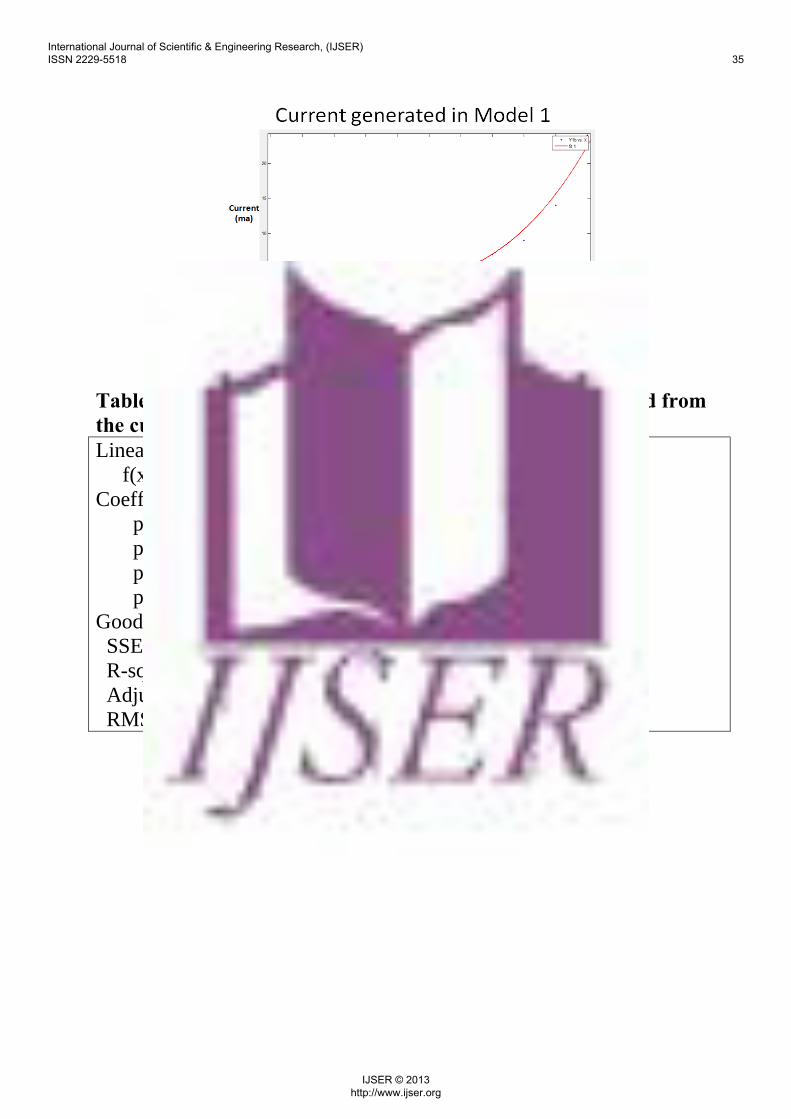
Fig 4.3 Current Generated in Model 1 Table 4.2.5 Equation of the Cubic Polynomial Curve obtained from the current generated in the wind turbine model 1 Linear model Poly3: f(x) = p1*x^3 + p2*x^2 + p3*x + p4 Coefficients (with 95% confidence bounds): p1 = 0.0004009 (3.426e-005, 0.0007676) p2 = -0.03016 (-0.06898, 0.008651) p3 = 0.8559 (-0.3794, 2.091) p4 = -6.909 (-18.32, 4.5) Goodness of fit: SSE: 16.25 R-square: 0.9699 Adjusted R-square: 0.957 RMSE: 1.523
International Journal of Scientific & Engineering Research, (IJSER) ISSN 2229-5518 35
IJSER © 2013 http://www.ijser.org

Fig 4.4 Voltage Generated in Model 2
Table 4.2.6 Equation of the Cubic Polynomial Curve obtained from the voltage generated in the wind turbine model 2 Linear model Poly3: f(x) = p1*x^3 + p2*x^2 + p3*x + p4 Coefficients (with 95% confidence bounds): p1 = -0.000575 (-0.002389, 0.00124) p2 = 0.09497 (-0.09711, 0.287) p3 = -2.533 (-8.646, 3.58) p4 = 16.52 (-39.94, 72.97) Goodness of fit: SSE: 397.9 R-square: 0.9579 Adjusted R-square: 0.9399 RMSE: 7.539
International Journal of Scientific & Engineering Research, (IJSER) ISSN 2229-5518 36
IJSER © 2013 http://www.ijser.org

Fig 4.5 Current Generated in Model 2
Table 4.2.7 Equation of the Cubic Polynomial Curve obtained from the current generated in the wind turbine model 2 Linear model Poly3: f(x) = p1*x^3 + p2*x^2 + p3*x + p4 Coefficients (with 95% confidence bounds): p1 = -0.0001166 (-0.0004758, 0.0002427) p2 = 0.01779 (-0.02024, 0.05581) p3 = -0.4648 (-1.675, 0.7454) p4 = 3 (-8.177, 14.18) Goodness of fit: SSE: 15.59 R-square: 0.9445 Adjusted R-square: 0.9207 RMSE: 1.493
The results presented as above show a stable and reasonably predictable outcome in terms of voltage and current output in the wind turbine generator. The 4 coefficients of the cubic polynomial function may be correlated with the different factors influencing the generator output.
International Journal of Scientific & Engineering Research, (IJSER) ISSN 2229-5518 37
IJSER © 2013 http://www.ijser.org
Chapter 5
5.1 Conclusion In the present project, an electromagnetic induction
generator and a small scale wind turbine are designed and modeled to
utilize the vibration and wind backlash generated during machine
operation as a means of energy harvest.
The generalized equation were also developed for
electromagnetic induction generator using vibration as a source and
small scale wind turbine generator using backlash wind as a source.
Both these small devices are tested and are found to produce
controlled electric power. Curves and equations generated from the
data obtained from the output voltage and current are found to be
correlated satisfactorily with the expected values.
5.2 Limitations
1) The magnets used in the model of electromagnetic induction
generator were not of appropriate quality and specification,
leading to unsatisfactory energy output.
2) The model of electromagnetic induction generator is to be
developed to respond to different levels and amplitudes of
vibrations, by suitable modification of the springs and
suspensions.
International Journal of Scientific & Engineering Research, (IJSER) ISSN 2229-5518 38
IJSER © 2013 http://www.ijser.org

3) Appropriated and high quality chemically insulated cables
should be used to prevent short circuiting of the armature coil
with the magnet and magnet holders.
4) The design and the making of the blades of the small scale wind
turbine model must be improved to achieve uniform output
voltage by the same quantity of blow.
5) The developed model of electromagnetic induction generator
was tested only in the controlled laboratory conditions. A
programmed simulation was also conducted. However, a real
time data in the practical field condition could not be obtained.
5.3 Future scope
1) With overcoming of the limitations as afore-mentioned, it is
possible to achieve,
a. A predictable and satisfactory energy output
b. Response to different levels and amplitudes of vibrations.
c. Uniform output voltage by the turbine in response to same
quantity of wind blow.
2) Energy harvested from the above sources may be utilized by
appropriate instrumentation and miniaturization to power the
commonly used wireless devices.
3) The output voltage or the current produced by the wind turbine
in response to mouth blowing by human respiratory effort may
be correlated with the human lung function in health and in
disease states.
International Journal of Scientific & Engineering Research, (IJSER) ISSN 2229-5518 39
IJSER © 2013 http://www.ijser.org

REFERENCE AND BIBLIOGRAPHY:
1. (International Energy Annual 2006 http://www.eia.gov/countries/data.cfm
2. El-Hami M, Glynne-Jones P, White N M, Hill M, Beeby S, James E, Brown A D and Ross J N 2001 Design and fabrication of a new vibration-based electromechanical power generator Sensors Actuators 92 483–6.
3. Beeby S P, Tudor M J, Koukharenko E, White N M, O’Donnell T, Saha C, Kulkharni S and Roy S 2005 Design and performance of a micro-electromagnetic vibration powered generator 13th Int. Conf. on Solid-State Sensors, Actuators and Microsystems vol 1 pp 780–3.
4. Beeby S P, Tudor M J and White N M 2006 Energy harvesting vibration sources for microsystems applications Meas. Sci. Technol. 17 175–95.
5. Glynne-Jones P, Tudor M J, Beeby S P and White N M 2004 An electromagnetic vibration-powered generator for intelligent sensor systems Sensors Systems A 110 344–9.
6. Waters R L, Chisum B, Jazo H and Fralick M 2008 Development of an electromagnetic transducer for energy harvesting of kinetic energy and its applicability to a MEMS-scale device Proc. Nano Power Forum.
7. Anton S R and Sodano H A 2007 A review of power harvesting from vibration using piezoelectric materials Smart Mater. Struct. 16 R1–21.
8. Roundy S, Wright P K and Pister K S J 2002 Micro-electrostatic vibration-to-electricity converters Proc. IMECE, ASME International Mechanical Engineering Congr. & Exhibition p 39309
9. Priya S 2007 Advances in energy harvesting using low profile piezoelectric transducers J. Electroceram. 19 165–82.
International Journal of Scientific & Engineering Research, (IJSER) ISSN 2229-5518 40
IJSER © 2013 http://www.ijser.org

10. Priya S and Inman D (ed) 2009 Energy Harvesting Technologies (New York: Springer Science+Business Media).
11. Wang L and Yuan F G 2007 Energy Harvesting by magnetostrictive material (MsM) for powering wireless sensors in SHM 14th Int. Symp. SPIE Smart Structures and Materials & NDE and Health Monitoring Wang L and Yuan F G 2008 Vibration energy harvesting by magnetostrictive material Smart Mater. Struct. 17 1–14.
12. Despesse G, Jager T, Chaillout J, Leger J, Vasiliev A, Basrour S and Chalot B 2005 Fabrication and characterisation of high damping electrostatic micro-devices for vibration energy scavenging Proc. Design, Test, Integration and Packaging of MEMS and MOEMS pp 386–90.
13. Lee Ch, Lim Y M, Yang B, Kotlanka R K, Heng Ch-H, He J H, Tang M, Xie J and Feng H 2009 Theoretical comparison of the energy harvesting capability among various electrostatic mechanisms from structure aspect Sensors Actuators A 156 208–16.
14. Cho S W, Jung H J and Lee I W 2007 Feasibility study of smart passive control system equipped with electromagnetic induction device Smart Mater. Struct. 16 2323–9.
15. Choi S B, Seong M S and Kim K S 2009 Vibration control of an electrorheological fluid-based suspension system with an energy regenerative mechanism Proc. Inar. Mech. Eng. D 223 459–69.
16. Muljadi, E., Golden, CO, Butterfield, C.P (2001) Pitch-controlled variable-speed wind turbine generation. Industry Applications, IEEE Transactions on. Nat. Wind Technol. Center, Nat. Renewable Energy Lab.,Volume: 37, Issue: 1; pp 240 – 246.
17. Slootweg, J.G., Polinder, H. ; Kling, W.L. (2001) Dynamic modelling of a wind turbine with doubly fed induction generator. Power Engineering Society Summer Meeting, 2001.
International Journal of Scientific & Engineering Research, (IJSER) ISSN 2229-5518 41
IJSER © 2013 http://www.ijser.org

Electr. Power Syst., Delft Univ. of Technol. Volume: 1, pp: 644 - 649
18. Nichita, C.; Luca, D. ; Dakyo, B.; Ceanga, E. (2002) Large band simulation of the wind speed for real time wind turbine simulators.Energy Conversion, IEEE Transactions on, Volume: 17, Issue: 4 pp: 523 – 529.
19. Miller, N.W.; Sanchez-Gasca, J.J.; Price, W.W.; Delmerico, R.W. (2003) Dynamic modeling of GE 1.5 and 3.6 MW wind turbine-generators for stability simulations. Power Engineering Society General Meeting, 2003, IEEE. Volume: 3, pp: 1977 – 1983.
20. Tapia, A.; Tapia, G. ; Ostolaza, J.X. ; Saenz, J.R. (2003): Modeling and control of a wind turbine driven doubly fed induction generator. Energy Conversion, IEEE Transactions on; Volume: 18, Issue: 2 :pp: 194 – 204.
21. Tan, K.; Islam, S. (2004): Optimum control strategies in energy conversion of PMSG wind turbine system without mechanical sensors. Energy Conversion, IEEE Transactions on. Volume: 19, Issue: 2 pp: 392 – 399.
22. Quincy Wang and Liuchen Chang (2004): An intelligent maximum power extraction algorithm for inverter-based variable speed wind turbine systems. Power Electronics, IEEE Transactions on Volume: 19, Issue: 5 pp: 1242 – 1249.
23. Yazhou Lei. ; Mullane, A. ; Lightbody, G. ; Yacamini, R. (2006): Modeling of the wind turbine with a doubly fed induction generator for grid integration studies. Energy Conversion, IEEE Transactions on Volume: 21, Issue: 1, pp: 257 – 264.
24. Liserre, M. ; Teodorescu, R. ; Blaabjerg, F. (2006): Stability of photovoltaic and wind turbine grid-connected inverters for a large set of grid impedance values. Power Electronics, IEEE Transactions on Volume: 21, Issue: 1 pp: 263 – 272.
International Journal of Scientific & Engineering Research, (IJSER) ISSN 2229-5518 42
IJSER © 2013 http://www.ijser.org

25. Xingjia Yao; Hongxia Sui ; Zuoxia Xing ; Dayong Liu (2007) The Dynamic Model of Doubly-fed Induction Generator Based on Wind Turbine. Automation and Logistics, 2007 IEEE International Conference on. Date of Conference: 18-21 Aug. 2007. pp: 1023 – 1027.
26. Wind flow and wastage (Betz’s Law)http://www.reuk.co.uk/Betz-Limit.htm
27. Parts of a General Wind Turbine http://en.wikipedia.org/wiki/File:EERE_illust_large_turbine.gif
28. Ferro Solutions Inc. @ (http://ferrosi.com). 29. Kinetron Company @ (http://www.kinetron.nl). 30. Lumedyne Technologies @
http://lumedynetechnologies.com). 31. Perpetuum Ltd @ (http://www.perpetuum.co.uk).
International Journal of Scientific & Engineering Research, (IJSER) ISSN 2229-5518 43
IJSER © 2013 http://www.ijser.org

APPENDIX-A
MATLAB program for the vibration test.
Q=.08; M=.7; l=.054; N=2000; a=[1 1.1 1.2 1.3 1.4 1.5 1.6 1.7 1.8 1.9 2 2.1 2.2 2.3 2.4 2.5 2.4 2.3 2.2 2.1 2 1.9 1.8 1.7 1.6 1.5 1.4 1.3 1.2 1.1 1 .9 .8 .7 .6 .5 .4 .3 .2 .1] for i=1:40 e(i)=(N*Q*l*(a(i)/M)^2)/2 end plot(a,e)
International Journal of Scientific & Engineering Research, (IJSER) ISSN 2229-5518 44
IJSER © 2013 http://www.ijser.org