design and development of solar panel ......iii certificate this is to certify that the project...
TRANSCRIPT
DESIGN AND DEVELOPMENT OF
SOLAR PANEL CLEANING SYSTEM
A project thesis for the fulfilment of the
requirements for the award of the degree of
Bachelor of Technology
in
Mechanical Engineering
and
Master of Technology
in
Mechatronics and Automation
by
SHAIKH TARIQ MOBIN
ROLL NO – 710ME4085
Under the Supervision of
Prof Subrata Kumar Panda
DEPARTMENT OF MECHANICAL ENGINEERING
NATIONAL INSTITUTE OF TECHNOLOGY
ROURKELA-769008, ODISHA (INDIA)
ii
DECLARATION
I hereby declare that to the best of my knowledge this submission is my own work and that it
contains no material previously published or written by another person nor material
which to a substantial extent has been accepted for the award of any other degree or diploma
of the university or other institute of higher learning, except where due
acknowledgement has been made in the text.
Date: 1st June, 2015 Shaikh Tariq Mobin
NIT Rourkela
iii
CERTIFICATE
This is to certify that the project entitled “Design and Development of
Solar Panel Cleaning System”, being submitted by Shaikh Tariq Mobin
bearing Roll No – 710me4085, has been carried out under my supervision for
the purpose of fulfilment of the requirements for the degree of Bachelor of
Technology in Mechanical Engineering and Master of Technology in
Mechatronics and Automation during the session 2014-2015 in the
Department of Mechanical Engineering, National Institute of Technology,
Rourkela.
To the best of my knowledge, this work has not been submitted to any
other University/Institute for the award of any degree or diploma.
(PROF. SUBRATA KUMAR PANDA)
DEPARTMENT OF MECHANICAL ENGINEERING
NIT ROURKELA
PLACE: ROURKELA
DATE: 30TH
MAY, 2015
NATIONAL INSTITUTE OF TECHNOLOGY,
ROURKELA

iv
ACKNOWLEDGEMENT
This report a result my efforts of my project work for the fulfilment of the requirements of
Dual Degree : B.Tech in Mechanical Engineering and M.Tech in Mechatronics and
Automation in the Department of Mechanical Engineering, NIT Rourkela. This project
would not have been possible without the active support and help by various people, whome I
wish to express my sincere gratitude.
I would first of all like to express my sincere thanks and gratitude to my mentor and
supervisor Prof. Subrata Kumar Panda who has been the constant driving force behind this
project. He provided me a liberal environment and gave me the required freedom to carry out
my project in an independent way. His inclination for incubating new ideas and deliver the
solution were always important sources of inspiration and motivation for me.
I am also very much thankful to my fellow classmates Ashish Singh, Chiranjibi Sahoo,
Abyarth Kumar Behera and Sheak Aftab Ali for constant support and suggestion in the entire
process.
Lastly, I would also like to thank my parents who were always behind me for the moral
support I required in this project.
v
ABSTARCT
Solar energy is the most abundant source of energy for all the forms of life on the planet
Earth. It is also the basic source for all the sources of energy except Nuclear Energy. But the
solar technology has not matured to the extent of the conventional sources of energy. It faces
lots of challenges such as high cost, erratic and unpredictable in nature, need for storage and
low efficiency. This project aims at increasing the efficiency of solar power plants by solving
the problem of accumulation of dust on the surface of solar panel which leads to reduction in
plant output and overall plant efficiency. It proposes to develop a Solar Panel Cleaning
System which could remove the accumulated dust on its surface on a regular basis and
maintain the solar power plant output. The system is a robotic system which could move
autonomously on the surface of solar panels by using pneumatic suction cups and use dry
methods for cleaning such as rotating cylindrical brush and vacuum cleaning system keeping
in mind the limited availability of water in areas where such plants are mainly located. This
project also aims to reduce the human involvement in the process of solar panel cleaning as it
is a very hazardous environment for them in scorching sun.
vi
CONTENTS
Declaration ........................................................................................................................................ i
Certificate…………………………………………………………………………………………………………………………………….ii
Acknowledgement……………………………………………………………………………………………………………………….iii
Abstract……………………………………………………………………………………………………………………………........….iv
List of Figures……………………………………………………………………………………………………………………………...vi
List of tables………………………………………………………………………………………………………………………………..vii
Introduction ...................................................................................................................................... 1
Autonomous Robot ....................................................................................................................... 1
Cleaning Robot .............................................................................................................................. 1
Literature Review ............................................................................................................................. 3
Removal of dust by Mechanical Method ........................................................................................ 3
Removal of Dust using nano-film ................................................................................................... 4
Super-Hydrophylic Material ..................................................................................................................... 4
Super-Hydrophobic Material .................................................................................................................... 4
Removal of Dust by Electrostatic Method ...................................................................................... 5
Key Problem ..................................................................................................................................... 7
Methodology .................................................................................................................................... 9
Locomotion Unit ............................................................................................................................ 9
Cleaning Unit ............................................................................................................................... 10
Linear Actuator ...................................................................................................................................... 10
Brush ..................................................................................................................................................... 11
Working Principle ........................................................................................................................... 12
Design and Component Specification ............................................................................................. 13
Locomotion Unit .......................................................................................................................... 13
Double Rack and Pinion.......................................................................................................................... 14
Pneumatic System ................................................................................................................................. 14
Structure ............................................................................................................................................... 15
Cleaning Unit ............................................................................................................................... 16
Linear Actuator ...................................................................................................................................... 16
Linear Actuator Platform ........................................................................................................................ 16
V – Wheel Assembly............................................................................................................................... 17
DC Motor ............................................................................................................................................... 17
Vacuum Pump ....................................................................................................................................... 18
Electronics ................................................................................................................................... 19
vii
Weight Estimation ....................................................................................................................... 20
Analysis and Calculation ................................................................................................................. 21
Static Analysis of Gear ................................................................................................................. 21
Conclusion ...................................................................................................................................... 26
References ...................................................................................................................................... 27
viii
List of Figures
Figure 1 Basic Structure of Electric Curtain ........................................................................................ 5
Figure 2 Single Phase Electric Curtain ................................................................................................ 5
Figure 3 Three Phase Electric Curtain ................................................................................................. 6
Figure 4: Monthly average maximum power output .......................................................................... 7
Figure 5 Working of Doube Rack and Pinion System .......................................................................... 9
Figure 6 Working of Prototype ........................................................................................................ 12
Figure 7 Locomotion Unit ................................................................................................................ 13
Figure 8 Double Rack and Pinion Arrangement ................................................................................ 14
Figure 9 Pneu8matic System ............................................................................................................ 14
Figure 10 Structure of the Legs ........................................................................................................ 15
Figure 11 Linear Actuator System .................................................................................................... 16
Figure 12 V - Gantry Plate ................................................................................................................ 16
Figure 13 V - Wheel Assembly.......................................................................................................... 17
Figure 14 DC Motor ......................................................................................................................... 17
Figure 15 Vacuum Pump .................................................................................................................. 18
Figure 16 Electronic Component Layout .......................................................................................... 19
Figure 17 Schematic Diagram of Electronic Circuit ........................................................................... 19
Figure 18 Model Information ........................................................................................................... 21

ix
List of Table
Table 1 Working of Double Rack and Pinion ..................................................................................... 10
Table 2 Weight Estimation ............................................................................................................... 20
1
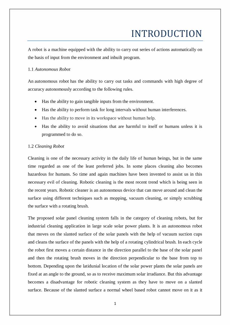
INTRODUCTION
A robot is a machine equipped with the ability to carry out series of actions automatically on
the basis of input from the environment and inbuilt program.
1.1 Autonomous Robot
An autonomous robot has the ability to carry out tasks and commands with high degree of
accuracy autonomously according to the following rules.
Has the ability to gain tangible inputs from the environment.
Has the ability to perform task for long intervals without human interferences.
Has the ability to move in its workspace without human help.
Has the ability to avoid situations that are harmful to itself or humans unless it is
programmed to do so.
1.2 Cleaning Robot
Cleaning is one of the necessary activity in the daily life of human beings, but in the same
time regarded as one of the least preferred jobs. In some places cleaning also becomes
hazardous for humans. So time and again machines have been invented to assist us in this
necessary evil of cleaning. Robotic cleaning is the most recent trend which is being seen in
the recent years. Robotic cleaner is an autonomous device that can move around and clean the
surface using different techniques such as mopping, vacuum cleaning, or simply scrubbing
the surface with a rotating brush.
The proposed solar panel cleaning system falls in the category of cleaning robots, but for
industrial cleaning application in large scale solar power plants. It is an autonomous robot
that moves on the slanted surface of the solar panels with the help of vacuum suction cups
and cleans the surface of the panels with the help of a rotating cylindrical brush. In each cycle
the robot first moves a certain distance in the direction parallel to the base of the solar panel
and then the rotating brush moves in the direction perpendicular to the base from top to
bottom. Depending upon the latidunial location of the solar power plants the solar panels are
fixed at an angle to the ground, so as to receive maximum solar irradiance. But this advantage
becomes a disadvantage for robotic cleaning system as they have to move on a slanted
surface. Because of the slanted surface a normal wheel based robot cannot move on it as it
2
will slip on its surface and fall on the ground. So we have used pneumatic system in which
the suction cups are placed on its bottom. These suction cups when actuated using the
vacuum pumps, create a suction force which helps the robot to get attached to its surface and
move on it.
3
LITERATURE REVIEW
As accumulation of dust on the PV panel reduces its transmittance which results in the
reduction of the power output, thus resulting in loss of power generation. This particular
problem is also responsible for the short life span of many interplanetary exploration
missions such as Mars Exploration Mission of Curiosity Rover as the power output from their
solar panel reduces over time because of the accumulation of dust. At a point of time density
of dust increases to level where power output declines to the extent which is not able to
support its vital functions.
Further this problem has also resulted in huge losses for the solar power plant operators
which suffer from reduced power output because of frequent dust storms. Most widely used
method of cleaning the solar panels is through the manual labour. Apart from being time
taking and cumbersome, there is also a risk of damage to the expensive solar panels by the
unskilled labour which is involved in this method.
The purpose of this project is to develop a semi-automatic self-cleaning mechanism for
cleaning the solar panel so that the process can become more reliable and fast, thus increasing
the power output of the solar power plant.
Various technologies being developed around the world for self-cleaning of solar panels are
discussed below:
2.1. Removal of dust using Mechanical Methods
There are different types of methods that are used to clean solar panel. Few of them are
mechanical vibration, ultrasonic cleaning, scrubbing and mopping.
When brushing is used for cleaning, it is mainly done with the help of brush or scrubber. In
these systems a brush is driven by using a machine, which are similar to automobile wipers.
But this cleaning method is not that efficient because of the sticky nature and small size of
the dust particle. It is also seen that difficult and harsh working condition of the solar power
plant make the maintenance of these machines difficult. Also the solar power plant is present
over a very large area which makes this cleaning method expensive and inefficient.
4
The process of blowing of air on the surface of the solar panel is an effective method but it
has some negative features such as low efficiency, huge energy usage and difficulty in
maintenance of blower arrangement.
Mechanical methods of cleaning also include ultrasonic and vibrating method. The factors
that are considered in this process include driving methodologies, amplitude and frequency of
vibration. Williams R. Brett [1] has used piezo electric and piezo ceramic actuation methods
for making self-cleaning solar panel system. These system work on the above described
vibrating method.
2.2 Removal of dust using Nano-Film.
When the solar panels have a layer of pellucid nano films capable of self-cleaning, it cleans
itself automatically. The Self Cleaning Nano-Films method mainly use two strategies for
cleaning the solar panel, namely Super-Hydrophilic Material or Super – Hydrophobic
Materials. These two strategies are explained below.
2.2.1. Super-Hydrophilic Material
TiO2 is one of the most popular super – Hydrophilic material which has both hydrophilic as
well as photocatalytic properties. This method has two stages in its cleaning process. In the
first stage, which is a photocatalytic process, the ultraviolet light falls on the TiO2 film and
the film reacts with it splitting the organic matters in the dust. Now in the second stage, the
hydrophilic nature of the TiO2 diffuses the rainwater on to the surface of the solar panel and
rinse the dust. But this method is not that popular because solar power plants are mainly
located in the arid region where rainfall is very scarce and erratic in nature.
2.2.2 Super-hydrophobic Material
Super-hydrophobic are those materials which show high level of repulsion to the water
molecules. For example leaves of lotus plant which are have very less wettability. In recent
times lot of studies have been conducted to replicate the hydro-phobic nature by forming
5
micro-structures or nano-structures. These structures are designed such that they create a
contact angle of more than 150o.
As a result of this, the water droplets that fall on these types
of surface roll off the surface, carrying organic and inorganic dust particles with them. Thus
cleaning the surface. But there is still a lot of scepticism in the application of super
hydrophobic material in self cleaning application. It is suggested that future studies should be
conducted to verify the feasibility of these types of materials in real world. [2-3]
2.3. Removal of dust using Electro-Static Methods
Technologies for removal of dust using electrostatic methods are mainly based on the
“Electric Curtain Concept” by F.B. Tatom and NASA in 1967 and further developed by
Masuda at the University of Tokyo in the 1970s [4]. In this technique electr-ostatic and
dielectro-phoretic forces are used to raise and transport charged and uncharged particles [5].
In recent past a lot of research has been done to apply this method in space application
especially in rovers that are being sent to moon and mars. Electric curtains technology uses a
series of parallel conducting electrodes which are embedded in a dielectric surface. Across
this surface an oscillation is transmitted between the electrode potentials.
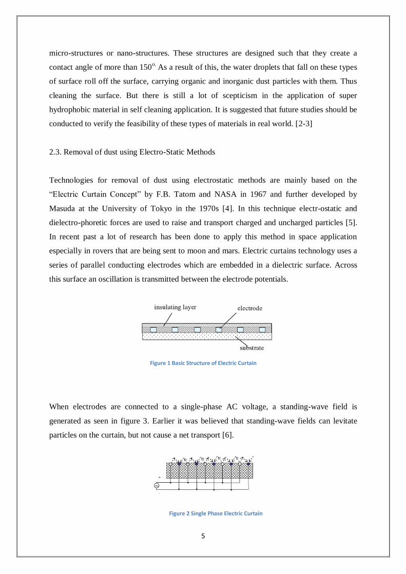
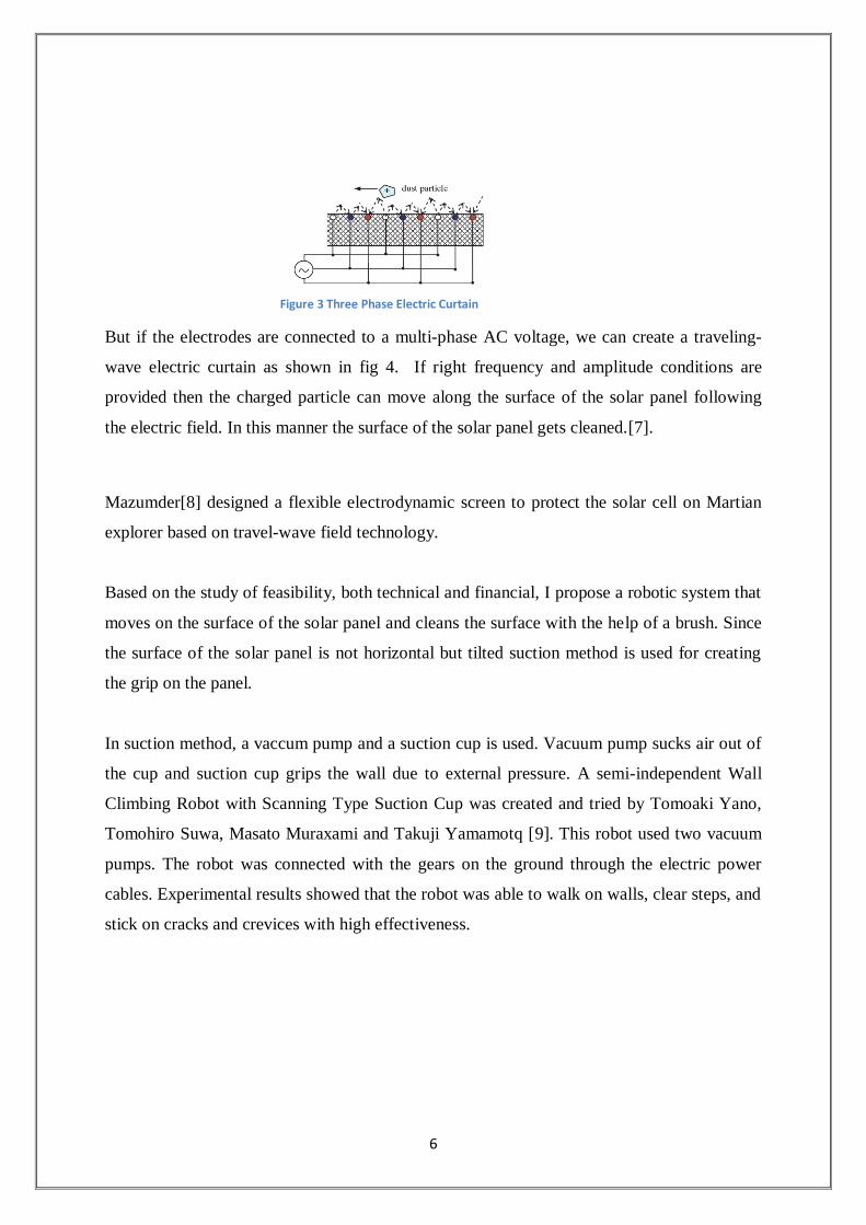
When electrodes are connected to a single-phase AC voltage, a standing-wave field is
generated as seen in figure 3. Earlier it was believed that standing-wave fields can levitate
particles on the curtain, but not cause a net transport [6].
Figure 1 Basic Structure of Electric Curtain
Figure 2 Single Phase Electric Curtain
6
But if the electrodes are connected to a multi-phase AC voltage, we can create a traveling-
wave electric curtain as shown in fig 4. If right frequency and amplitude conditions are
provided then the charged particle can move along the surface of the solar panel following
the electric field. In this manner the surface of the solar panel gets cleaned.[7].
Mazumder[8] designed a flexible electrodynamic screen to protect the solar cell on Martian
explorer based on travel-wave field technology.
Based on the study of feasibility, both technical and financial, I propose a robotic system that
moves on the surface of the solar panel and cleans the surface with the help of a brush. Since
the surface of the solar panel is not horizontal but tilted suction method is used for creating
the grip on the panel.
In suction method, a vaccum pump and a suction cup is used. Vacuum pump sucks air out of
the cup and suction cup grips the wall due to external pressure. A semi-independent Wall
Climbing Robot with Scanning Type Suction Cup was created and tried by Tomoaki Yano,
Tomohiro Suwa, Masato Muraxami and Takuji Yamamotq [9]. This robot used two vacuum
pumps. The robot was connected with the gears on the ground through the electric power
cables. Experimental results showed that the robot was able to walk on walls, clear steps, and
stick on cracks and crevices with high effectiveness.
Figure 3 Three Phase Electric Curtain

7
KEY PROBLEM
A number of environmental factors such as wind speed, humidity, ambient temperature, solar
radiation, atmospheric dust and direction influences the power generation process using
installed solar photovoltaic modules. Dust build-up on solar module surface is an issue of
great worry, particularly in desert provinces where infrequent to regular dust storms do occur.
The glass cover transmittance decreases because of accretion of dust on the surface of PV
module, which ultimately decreases the amount of solar irradiation reaching the cells. The
dust density of the surface, orientation, the tilt angle, exposure period, dominant wind
direction, and site climatic conditions determines the reduction in glass transmittance [1,2].
The density of deposited dust, the composition of the dust and its particle distribution
determines the effect of the effect of dust on the power output and current -voltage (I~V)
characteristics of PV modules [3,4].
Surveys in Saudi Arabia to study the effect of dust amassing on power production of solar
module have revealed that power provided by the modules declined constantly due to dust
addition [6]. Pmax which is the average of daily peak power output in a month, for the period
of the investigation is shown in Fig. 1.
Figure 4: Monthly average maximum power output

8
The modules power outputs reduced by twenty percent due to a single dust storm in March
irrespective of the technology and evaluation. In November, the power production for all the
modules amplified to their uppermost values due to rainfall; however it did not recover fully
to the original power output at the beginning of the examination. Nevertheless, in one
cleaning routine (Dec-Mar) in which the modules were cleaned was in a week, the power
outputs of the modules remained high. Without further cleaning from April, the power
productions began to reduction again.
When PV modules are exposed to real outdoor condition for a long period, it was observed
that the performance decreases gradually with dust build-up lest the modules are cleaned by
rain or human action. The power output decreases by more than half if no cleaning is
accomplished on modules that exceeds six months. Reduction in power output due to dust
build-up does not depend only on the length of module exposure, but also on the occurrence
and strength of dust.
Subsequently, it is suggested that installed PV modules should be cleaned at least once in two
weeks. Nevertheless, in the time when sandstorm occurs, immediate cleaning of the solar
modules should be performed. It was observed that rainfall improved the power production of
dusty solar modules, yet it cannot be trusted upon for cleaning since it is not foreseeable.
9
METHODOLOGY
The solar panel cleaning system consists of two basic system unit depending on their
functioning, namely Locomotion Unit and Cleaning Unit.
4.1. Locomotion Unit
Locomotion Unit is responsible for the movement of robot on the surface of the solar panel.
Since the solar panels are mounted at an angle to ground level so as to capture maximum
solar irradiance, the robot cannot rely entirely on the conventional wheel based system for its
movement. The inclined surface of the solar panel demands for a movement mechanism that
can stick to the surface of the panel and prevent the robot from sliding on the surface. So the
pneumatic suction system was used along with a double rack and pinion mechanism.
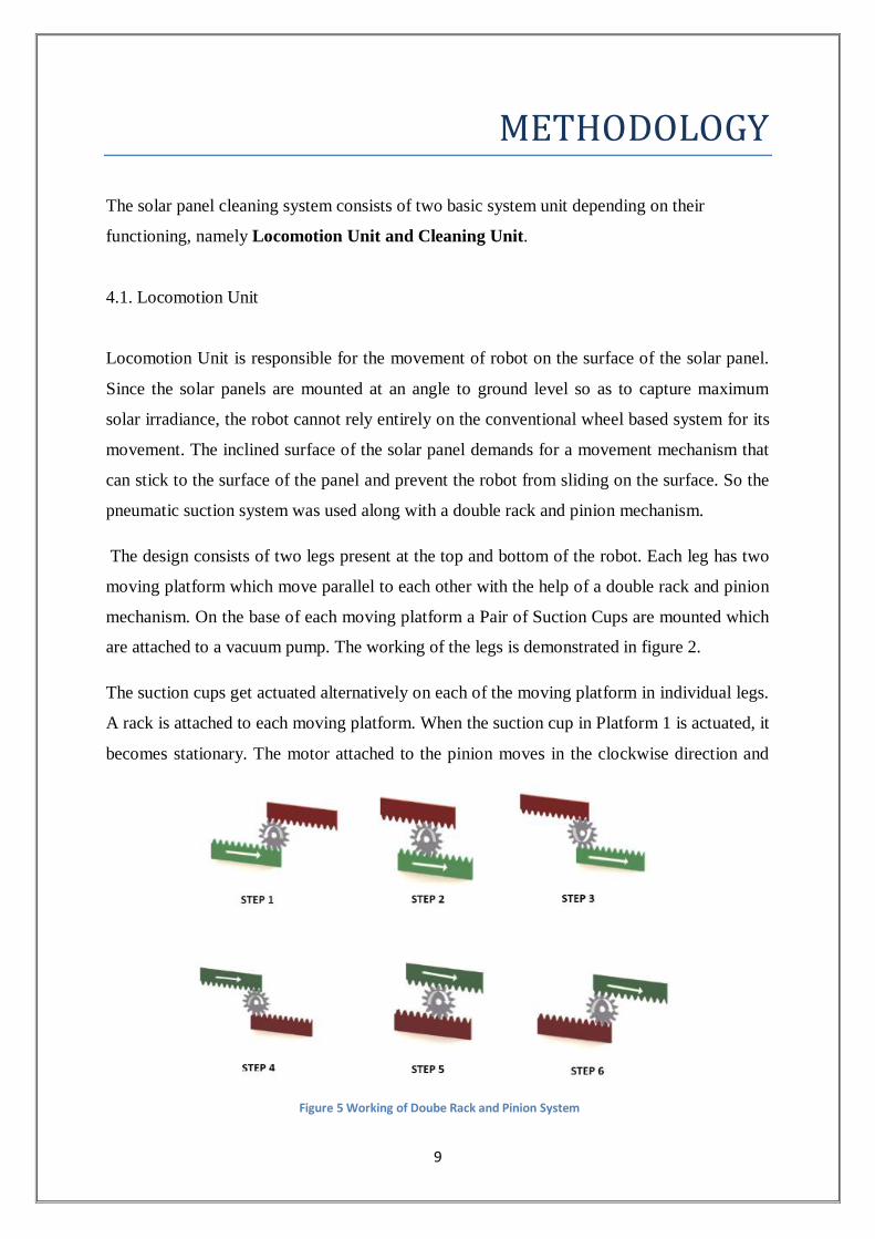
The design consists of two legs present at the top and bottom of the robot. Each leg has two
moving platform which move parallel to each other with the help of a double rack and pinion
mechanism. On the base of each moving platform a Pair of Suction Cups are mounted which
are attached to a vacuum pump. The working of the legs is demonstrated in figure 2.
The suction cups get actuated alternatively on each of the moving platform in individual legs.
A rack is attached to each moving platform. When the suction cup in Platform 1 is actuated, it
becomes stationary. The motor attached to the pinion moves in the clockwise direction and
Figure 5 Working of Doube Rack and Pinion System

10
the pinion moves on platform 1. As a result the rack attached to platform 2 also moves in the
forward direction. Once the pinion reaches to the end of the first rack the motor stops and the
suction cups on platform 2 actuates making it stationary. In the same time the suction cups
attached to platform 1 gets disengaged making it mobile. Now the pinion moves in the
anticlockwise direction on the rack attached to the platform 2. So the platform 1 now moves
in the forward direction. This cycle repeats itself for moving the robot in the forward
direction.
4.2. Cleaning Unit
Cleaning Unit is responsible for taking care of the cleaning action of the robot. It is placed
perpendicular to both the legs. Both the legs are present in at the opposite end of the cleaning
unit. Cleaning unit consists of two main parts, namely, Linear Actuator and the Rotating
Brush.
4.2.1 Linear Actuator
Linear actuator is an actuator that creates motion in a straight line, in contrast to the circular
motion of a conventional electric motor. Linear actuator is used in machine tools and
industrial machinery, in computer peripherals, in valve and dam and dampers. There are
Step Rack
1
Rack
2
Pinion Motion Remark
1 Fixed Mobile Anti-Clockwise Rack 2 Moves in
forward Direction
Pinion at extreme
end
2 Fixed Mobile Anti-Clockwise Rack 2 Moves in
forward Direction
Pinion in Middle
3 Fixed Mobile Anti-Clockwise Rack 2 reach extreme
end
Pinion In extreme
end
4 Mobile Fixed Clockwise Rack 1 Moves in
forward Direction
Pinion at extreme
end
5 Mobile Fixed Clockwise Rack 1 Moves in
forward Direction
Pinion in Middle
6 Mobile Fixed Clockwise Rack 1 reach extreme
end
Pinion In extreme
end
Table 1 Working of Double Rack and Pinion
11
various categories of linear actuators depending upon the mechanism used and power source,
namely, mechanical actuators, hydraulic actuators, pneumatic actuators, piezoelectric
actuators, electro-mechanical actuators, linear motor and telescopic linear actuators.
In this project we propose to use electro-mechanical linear actuator, which works on the
principle of conversion of rotary motion of the electric motor into the linear motion. This
actuator consists of a stepper motor mounted at one end of the aluminium rail. A platform
moves on the rail with the help of v-wheels and idler pulley. A timing belt is attached to the
platform and is run by the stepper motor. Thus the circular motion of the motor is converted
in the linear motion.
The linear actuator also acts as the central spine which connects both the legs. The platform
also carries the cylindrical brush with it. So as the platform does a “to and fro” linear motion
on the rails so does the brush attached to it.
4.2.2. Brush
The brush is responsible for scrubbing and dusting away of the dust accumulated on the
surface of the solar panel. It is attached to the v-slot gantry plate platform which moves in the
linear actuator. The brush is mounted on radial bearing which is rotated with the help of a 12
volt DC motor.
12
WORKING
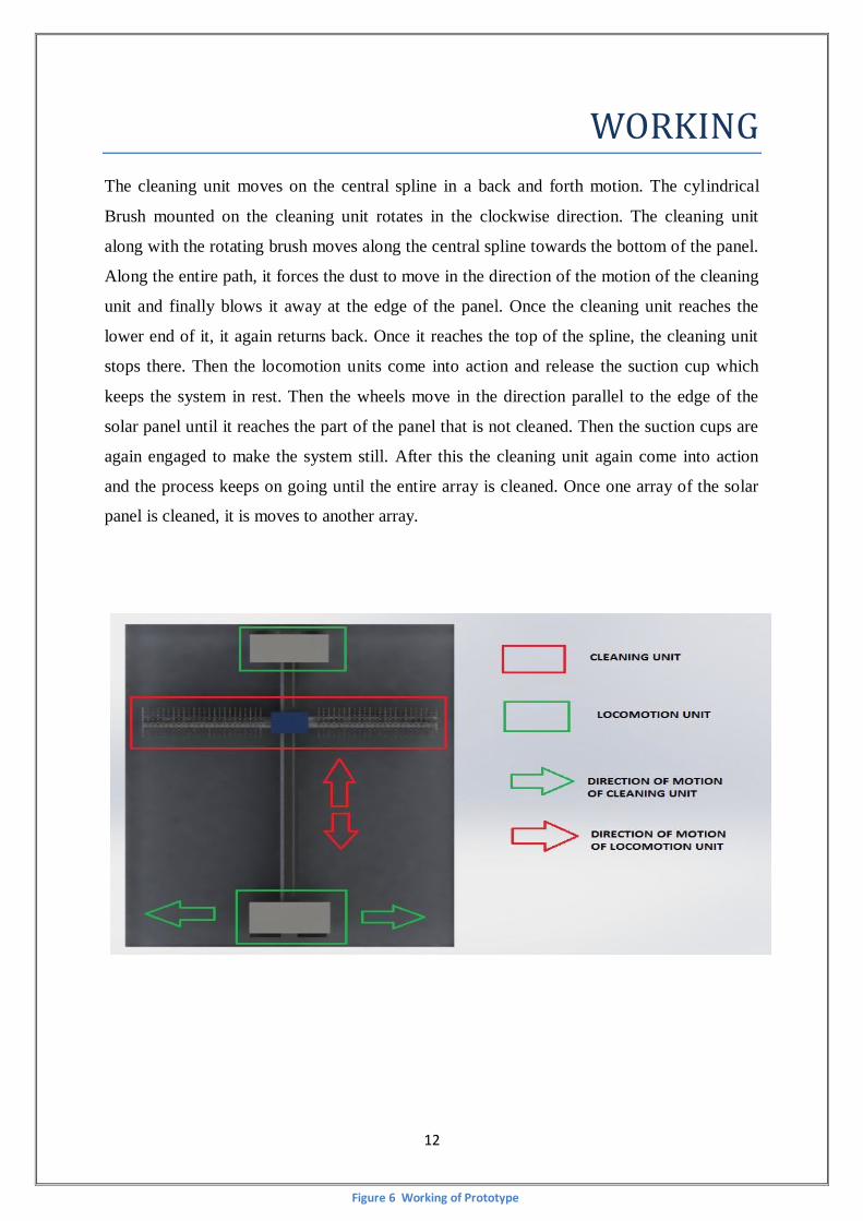
The cleaning unit moves on the central spline in a back and forth motion. The cylindrical
Brush mounted on the cleaning unit rotates in the clockwise direction. The cleaning unit
along with the rotating brush moves along the central spline towards the bottom of the panel.
Along the entire path, it forces the dust to move in the direction of the motion of the cleaning
unit and finally blows it away at the edge of the panel. Once the cleaning unit reaches the
lower end of it, it again returns back. Once it reaches the top of the spline, the cleaning unit
stops there. Then the locomotion units come into action and release the suction cup which
keeps the system in rest. Then the wheels move in the direction parallel to the edge of the
solar panel until it reaches the part of the panel that is not cleaned. Then the suction cups are
again engaged to make the system still. After this the cleaning unit again come into action
and the process keeps on going until the entire array is cleaned. Once one array of the solar
panel is cleaned, it is moves to another array.
Figure 6 Working of Prototype
13
DESIGN AND COMPONENT SPECIFICATION
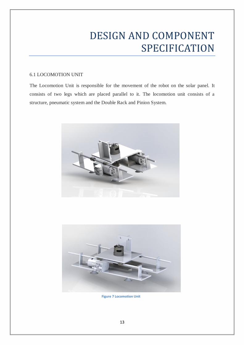
6.1 LOCOMOTION UNIT
The Locomotion Unit is responsible for the movement of the robot on the solar panel. It
consists of two legs which are placed parallel to it. The locomotion unit consists of a
structure, pneumatic system and the Double Rack and Pinion System.
Figure 7 Locomotion Unit
14
The locomotion unit consist of three basic Components:
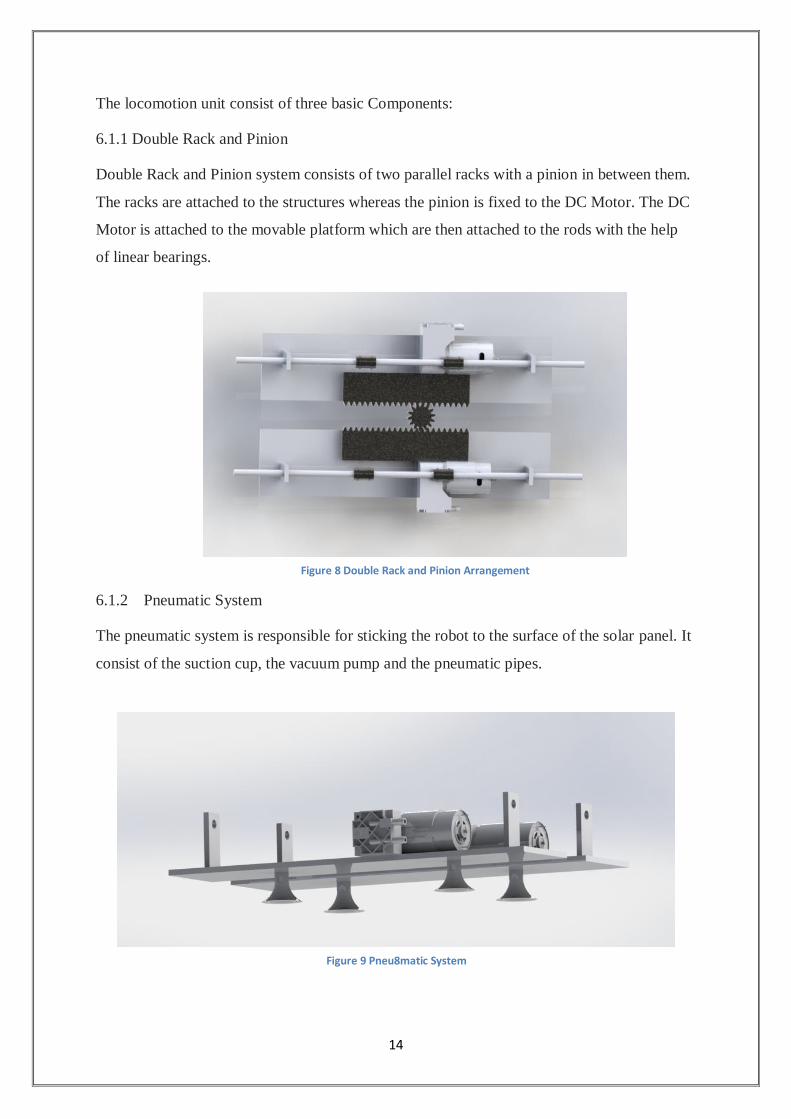
6.1.1 Double Rack and Pinion
Double Rack and Pinion system consists of two parallel racks with a pinion in between them.
The racks are attached to the structures whereas the pinion is fixed to the DC Motor. The DC
Motor is attached to the movable platform which are then attached to the rods with the help
of linear bearings.
6.1.2 Pneumatic System
The pneumatic system is responsible for sticking the robot to the surface of the solar panel. It
consist of the suction cup, the vacuum pump and the pneumatic pipes.
Figure 8 Double Rack and Pinion Arrangement
Figure 9 Pneu8matic System
15
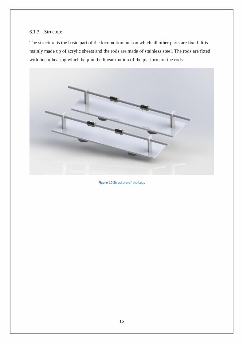
6.1.3 Structure
The structure is the basic part of the locomotion unit on which all other parts are fixed. It is
mainly made up of acrylic sheets and the rods are made of stainless steel. The rods are fitted
with linear bearing which help in the linear motion of the platform on the rods.
Figure 10 Structure of the Legs
16
6.2 Cleaning Unit
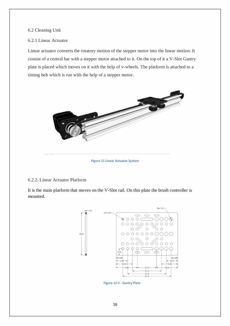
6.2.1 Linear Actuator
Linear actuator converts the rotatory motion of the stepper motor into the linear motion. It
consist of a central bar with a stepper motor attached to it. On the top of it a V-Slot Gantry
plate is placed which moves on it with the help of v-wheels. The platform is attached to a
timing belt which is run with the help of a stepper motor.
6.2.2. Linear Actuator Platform
It is the main platform that moves on the V-Slot rail. On this plate the brush controller is
mounted.
Figure 11 Linear Actuator System
Figure 12 V - Gantry Plate
17
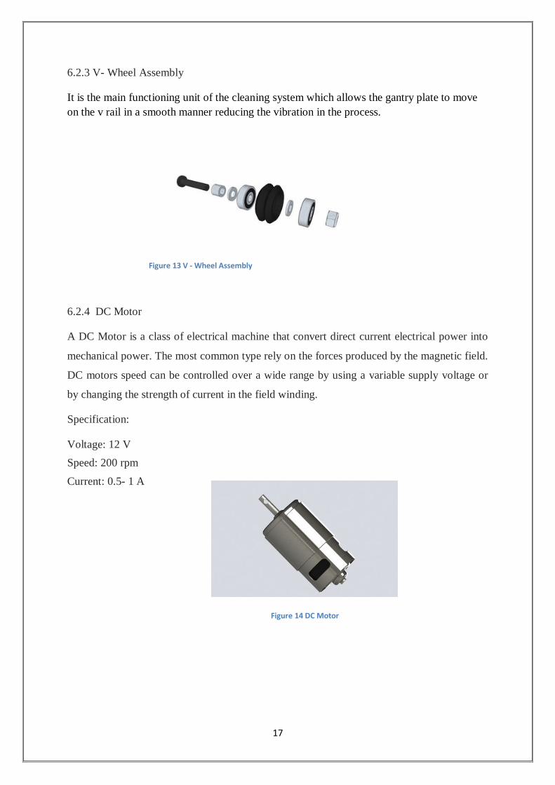
6.2.3 V- Wheel Assembly
It is the main functioning unit of the cleaning system which allows the gantry plate to move
on the v rail in a smooth manner reducing the vibration in the process.
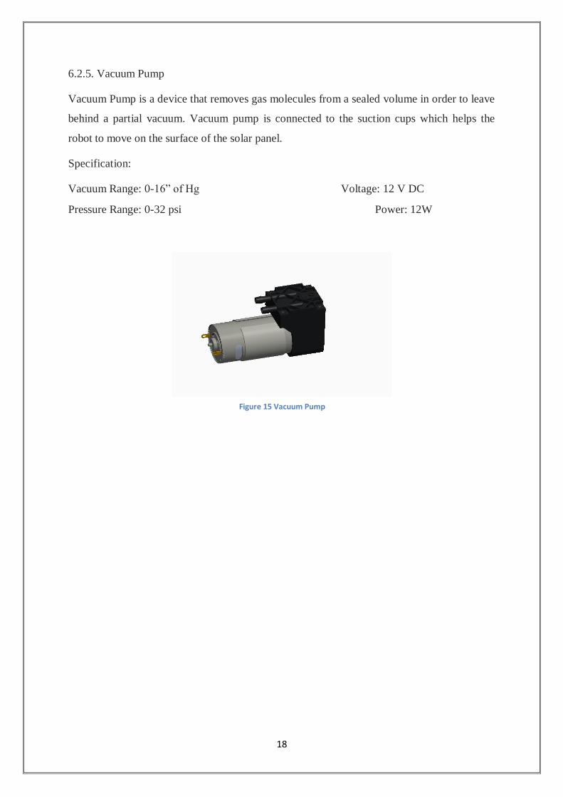
6.2.4 DC Motor
A DC Motor is a class of electrical machine that convert direct current electrical power into
mechanical power. The most common type rely on the forces produced by the magnetic field.
DC motors speed can be controlled over a wide range by using a variable supply voltage or
by changing the strength of current in the field winding.
Specification:
Voltage: 12 V
Speed: 200 rpm
Current: 0.5- 1 A
Figure 13 V - Wheel Assembly
Figure 14 DC Motor
18
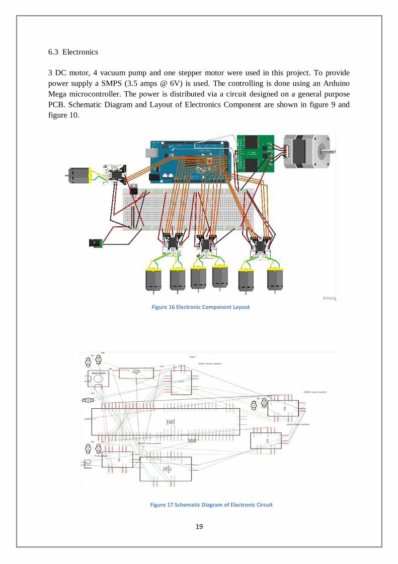
6.2.5. Vacuum Pump
Vacuum Pump is a device that removes gas molecules from a sealed volume in order to leave
behind a partial vacuum. Vacuum pump is connected to the suction cups which helps the
robot to move on the surface of the solar panel.
Specification:
Vacuum Range: 0-16” of Hg Voltage: 12 V DC
Pressure Range: 0-32 psi Power: 12W
Figure 15 Vacuum Pump
19
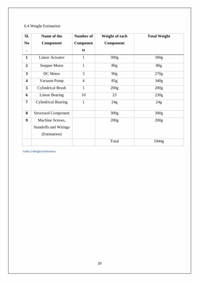
Figure 17 Schematic Diagram of Electronic Circuit
6.3 Electronics
3 DC motor, 4 vacuum pump and one stepper motor were used in this project. To provide
power supply a SMPS (3.5 amps @ 6V) is used. The controlling is done using an Arduino
Mega microcontroller. The power is distributed via a circuit designed on a general purpose
PCB. Schematic Diagram and Layout of Electronics Component are shown in figure 9 and
figure 10.
Figure 16 Electronic Component Layout
20
6.4 Weight Estimation
Sl.
No
.
Name of the
Component
Number of
Componen
ts
Weight of each
Component
Total Weight
1 Linear Actuator 1 300g 300g
2 Stepper Motor 1 80g 80g
3 DC Motor 3 90g 270g
4 Vacuum Pump 4 85g 340g
5 Cylindrical Brush 1 200g 200g
6 Linear Bearing 10 23 230g
7 Cylindrical Bearing 1 24g 24g
8 Structural Component 300g 300g
9 Machine Screws,
Standoffs and Wirings
(Estimation)
200g 200g
Total 1944g
Table 2 Weight Estimation
21
ANALYSIS AND CALCULATION
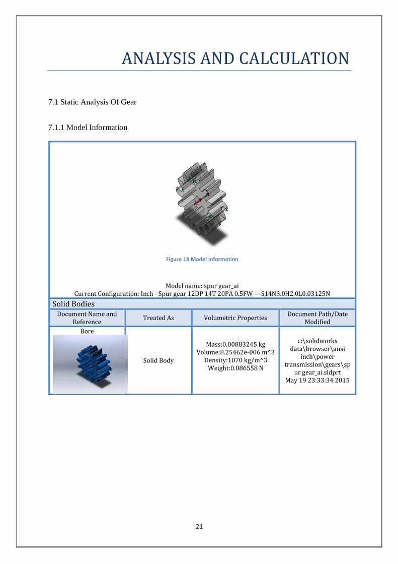
7.1 Static Analysis Of Gear
7.1.1 Model Information
Figure 18 Model Information
Model name: spur gear_ai Current Configuration: Inch - Spur gear 12DP 14T 20PA 0.5FW ---S14N3.0H2.0L0.03125N
Solid Bodies Document Name and
Reference Treated As Volumetric Properties
Document Path/Date Modified
Bore
Solid Body
Mass:0.00883245 kg Volume:8.25462e-006 m^3
Density:1070 kg/m^3 Weight:0.086558 N
c:\solidworks data\browser\ansi
inch\power transmission\gears\sp
ur gear_ai.sldprt May 19 23:33:34 2015
22
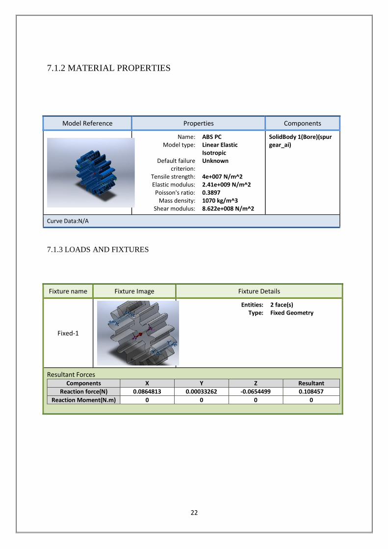
7.1.2 MATERIAL PROPERTIES
7.1.3 LOADS AND FIXTURES
Model Reference Properties Components
Name: ABS PC Model type: Linear Elastic
Isotropic Default failure
criterion: Unknown
Tensile strength: 4e+007 N/m^2 Elastic modulus: 2.41e+009 N/m^2
Poisson's ratio: 0.3897 Mass density: 1070 kg/m^3
Shear modulus: 8.622e+008 N/m^2
SolidBody 1(Bore)(spur gear_ai)
Curve Data:N/A
Fixture name Fixture Image Fixture Details
Fixed-1
Entities: 2 face(s) Type: Fixed Geometry
Resultant Forces Components X Y Z Resultant
Reaction force(N) 0.0864813 0.00033262 -0.0654499 0.108457
Reaction Moment(N.m) 0 0 0 0

23
LOADS AND FIXTURES
Load name Load Image Load Details
Gravity-1
Reference: Plane3 Values: 0 0 -9.81
Units: SI
Torque-1
Reference: Face< 1 > Type: Apply torque
Value: 0.5 N.m Phase Angle: 0
Units: deg
7.1.4 MESH
Mesh Control Name Mesh Control Image Mesh Control Details
Control-1
Entities: 26 face(s) Units: in
Size: 0.036814 Ratio: 1.5
24
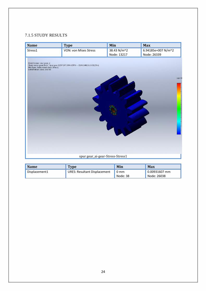
7.1.5 STUDY RESULTS
Name Type Min Max
Stress1 VON: von Mises Stress 38.43 N/m^2 Node: 13217
6.94185e+007 N/m^2 Node: 26339
spur gear_ai-gear-Stress-Stress1
Name Type Min Max
Displacement1 URES: Resultant Displacement 0 mm Node: 38
0.00931607 mm Node: 26038
25
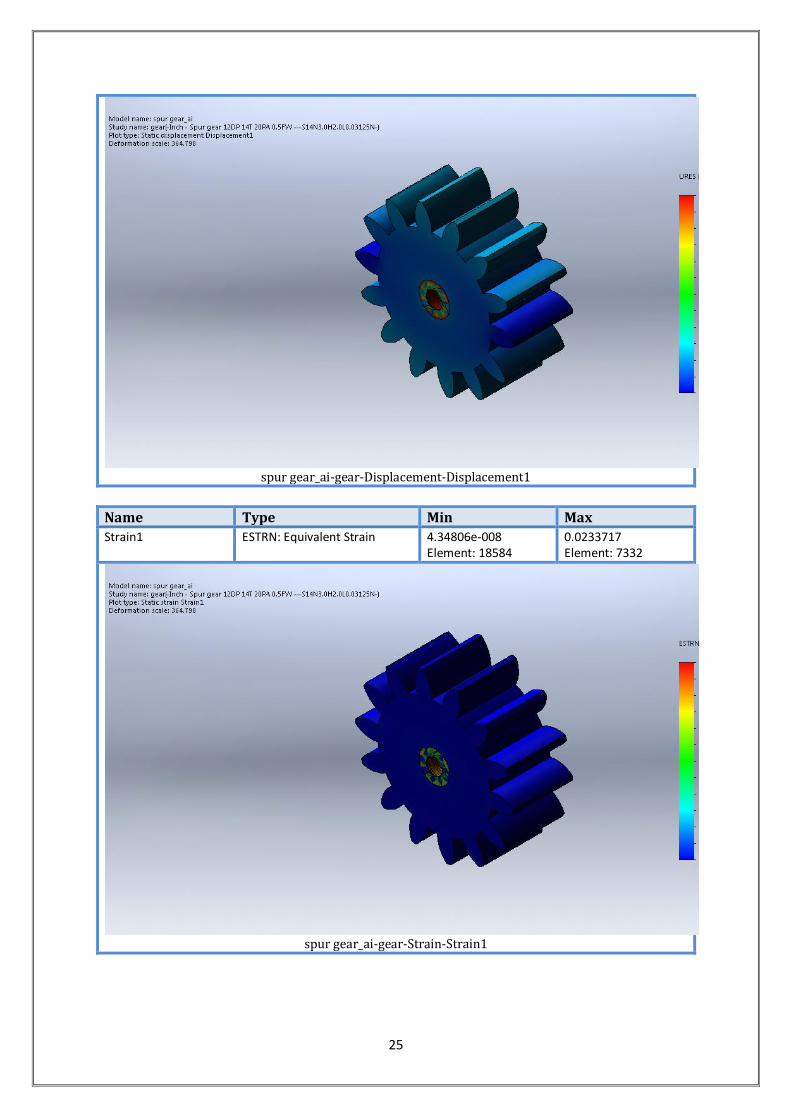
spur gear_ai-gear-Displacement-Displacement1
Name Type Min Max
Strain1 ESTRN: Equivalent Strain 4.34806e-008 Element: 18584
0.0233717 Element: 7332
spur gear_ai-gear-Strain-Strain1
26
CONCLUSION
The solar panel cleaning system was first designed taking into consideration the design parameters.
At first the CAD model was made using Solidworks. The cad model was simulated to check the
validity of the design.
The cad model was then fabricated using according to the CAD design.
The prototype was tested and the following observations were made:
1. The Double Rack and Pinion Mechanism worked as it was designed to do.
2. The suction cups were able to stick to the surface of the panel, but they were not able to
stick longer.
3. The entire design was unstable in nature which created lots of disturbances while in
operation.
4. The linear actuator system worked very nicely and was able to achieve the required design
parameter.
5. The cleaning action of the brush was good but it failed to scrub the dust which was sticky in
nature.
6. The sticky dusts need to be removes using hard brush or through mopping action.
27
REFERENCES
[1] Williams R B, Tanimoto R, Simonyan A, et al. Vibration characterization of self-cleaning
solar panels with piezoceramic actuation. Collection of Technical Papers - 48th
AIAA/ASME/ASCE/AHS/ASC Structures, Structural Dynamics, and Materials Conference ,
2007; pp. 512-520.
[2] Park Y B, Im H, Im M, et al. Self-cleaning effect of highly water-repellent microshell
structures for solar cell applications. Journal of Materials Chemistry, 2011; 21:633–636.
[3]Zhu Jia, Hsu Ching Mei, Yu Zongfu, et al. Nanodome solar cells with efficient light
management and self-cleaning. Nano Letter, 2010; 10:1979–1984.
[4] Masuda S, Aoyoma M. Characteristics of electric dust collector based on electric curtain.
Proceedings of the General Conference of the Institute of Electronic Engineers. Japan, 1971,
No. 821 Proc. of Albany Conference on Electrostatics (1971).
[5] Calle C I, McFall J L, Buhler C R, et al. Dust particle removal by electrostatic and
dielectrophoretic forces with applications to NASA exploration missions. Proc. ESA Annual
Meeting on Electrostatics, 2008; Paper O1.
[6] Liu G, Marshall J S. Particle transport by standing waves on an electric curtain. Journal of
Electrostatics, 2010; 68: 289-
298.
[7] Liu G Q, Marshall J S. Effect of particle adhesion and interactions on motion by traveling
waves on an electric curtain. Journal of Electrostatics, 2010; 68:179-189.
[8] Sharma R, Wyatt C A, Zhang Jing, et al. Experimental evaluation and analysis of
electrodynamic screen as dust mitigation technology for future Mars missions. IEEE
Transactions on Industry Applications, 2009; 45( 2):591-596.
[9] Tomoaki Yano, Tomohiro Suwa, Masato Muraxami And Takuji Yamamotq Development
of a Semi Self-contained Wall Climbing Robot with Scanning Type Suction Cups Intelligent
Robots and Systems, 1997. IROS '97., Proceedings of the 1997 IEEE/RSJ International
Conference
[10] Hegazy AA. Effect of dust accumulation on solar transmittance through glass covers of
plate-type collectors. J Renew Energy 2001;22:525e40.
[11] El-Shobokshy MS, Mujahid A, Zakzouk AKM. Effects of on the performance of
concentrator photovoltaic cells, IEE Proc Feb. 1985;132(1). Pt. I.
[12] El-Shobokshy MS, Hussein FM. Degradation of photovoltaic cell performance due to
dust deposition on to its surface. J Renew Energy 1993;3(6/7):585e90.