design and evaluation of a versatile and efficient receiver
TRANSCRIPT
Design and Evaluation of a Versatile and EfficientReceiver-Initiated Link Layer for Low-Power Wireless
Prabal Dutta†, Stephen Dawson-Haggerty‡, Yin Chen⋆, Chieh-Jan Mike Liang⋆, and Andreas Terzis⋆
†Computer Science & Eng. Division
‡Computer Science Division
⋆Computer Science Department
University of Michigan University of California, Berkeley Johns Hopkins University
Ann Arbor, MI 48109 Berkeley, CA 94720 Baltimore, MD 21218
[email protected] [email protected] yinchen,cliang4,[email protected]
AbstractWe present A-MAC, a receiver-initiated link layer for
low-power wireless networks that supports several servicesunder a unified architecture, and does so more efficiently andscalably than prior approaches. A-MAC’s versatility stemsfrom layering unicast, broadcast, wakeup, pollcast, and dis-covery above a single, flexible synchronization primitive. A-MAC’s efficiency stems from optimizing this primitive andwith it the most consequential decision that a low-power linkmakes: whether to stay awake or go to sleep after probing thechannel. Today’s receiver-initiated protocols require moretime and energy to make this decision, and they exhibit worsejudgment as well, leading to many false positives and nega-tives, and lower packet delivery ratios. A-MAC begins tomake this decision quickly, and decides more conclusivelyand correctly in both the negative and affirmative. A-MAC’sscalability comes from reserving one channel for the initialhandshake and different channels for data transfer. Our re-sults show that: (i) a unified implementation is possible; (ii)A-MAC’s idle listening power increases by just 1.12× un-der interference, compared to 17.3× for LPL and 54.7× forRI-MAC; (iii) A-MAC offers high single-hop delivery ratios,even with multiple contending senders; (iv) network wakeupis faster and far more channel efficient than LPL; and (v)collection routing performance exceeds the state-of-the-art.
Categories and Subject DescriptorsC.2.2 [Computer-Communication Networks]: Net-
work Protocols
General TermsDesign, Experimentation, Performance, Standardization
KeywordsLink protocols, MAC protocols, wireless sensor networks
Permission to make digital or hard copies of all or part of this work for personal orclassroom use is granted without fee provided that copies are not made or distributedfor profit or commercial advantage and that copies bear this notice and the full citationon the first page. Copyrights for components of this work owned by others than ACMmust be honored. Abstracting with credit is premitted. To copy otherwise, to republish,to post on servers or to redistribute to lists, requires prior specific permission and/or afee.SenSys’10, November 3–5, 2010, Zurich, Switzerland.Copyright 2010 ACM 978-1-4503-0344-6/10/11 ...$10.00
1 IntroductionA receiver-initiated link layer is one in which the re-
ceiver triggers communications by first transmitting a probe.Receiver-initiated protocols have experienced a renewed in-terest because they offer many benefits over sender-initiatedprotocols for low-power wireless: they [17, 33] handle hid-den terminals better than sender-initiated ones [30, 38, 39];their low-power probing (LPP) mechanism ([28]) supportsasynchronous communications but avoids the long pream-bles of sender-initiated low-power listening (LPL, [20, 30])which run afoul of regulatory standards [2]; they support ex-tremely low duty cycles [28] or high data rates [33]; and theysupport many low-power services including wakeup [12],discovery [11], broadcast [32], anycast [13], and pollcast [9].
Despite these many benefits, receiver-initiated protocolsface a number of drawbacks as well. Their fundamental syn-chronization primitive – the probe – costs more than channelsampling, which means that baseline power draw is higherthan sender-initiated protocols. Their frequent probe trans-missions can congest the channel and delay data communi-cations, which affects their scalability under even light trafficloads. Their use of incompatible probe semantics for differ-ent services makes concurrent use of those services difficult:some probes use hardware acknowledgments [13, 28] whileothers do not [9, 33]; some probes include only receiver-specific data [28, 33] while others may also include sender-specific data [9, 13]; and some probes include contentionwindows [13, 33] while others do not [9, 28]. These dif-ferences raise the question of whether it is possible to designa general-purpose, yet efficient, receiver-initiated link layer.
In this paper, we present A-MAC, a new receiver-initiatedlink layer that shows it is possible to support multiple ser-vices under a unified architecture, and to do so more effi-ciently and scalably than prior designs. Thus, we narrowthe gap between sender- and receiver-initiated approaches tolow-power wireless. A-MAC uses the backcast synchroniza-tion primitive – a probe/ack frame exchange – to determinequickly, robustly, and in constant time whether inbound traf-fic is pending [13]. All other services are multiplexed abovethe primitive or piggybacked on the probe. To minimize con-tention between probe and data traffic, A-MAC (optionally)uses one or more secondary channels to complete data trans-fer after the initial probe, allowing A-MAC to scale with den-sity and load [22, 25]. Section 3 presents the A-MAC design.
1

Lacking proper hardware support, A-MAC achieves itshigh performance by dynamically reassigning hardware ad-dresses, making use of hardware address recognition, andleveraging hardware acknowledgment collisions. Whilethese mechanisms misappropriate addresses, violate stan-dards, and abuse acknowledgments, the underlying ideas aremore principled, and we believe they highlight new direc-tions for radio hardware and link protocols. The techniquesallow us to implement unicast, broadcast, wakeup, and poll-cast using today’s off-the-shelf radios within a unified frame-work that exposes a standard TinyOS ActiveMessage in-terface, allowing drop-in use with many existing codebases.Our description omits asynchronous neighbor discovery dueto space constraints, but supporting discovery is a matter ofsystematically scheduling the probe and listen times [11].Section 4 details our prototype implementation, and the var-ious mechanisms we employ, to demonstrate the value ofhardware support for a receiver-initiated link layer.
Sections 5 and 6 explore A-MAC’s microbenchmarks andmacrobenchmarks, respectively. Key microbenchmarks in-clude evaluating the robustness of the fundamental synchro-nization mechanism (including effects of path delays, pathloss, and neighborhood density). We also provide energy mi-crobenchmarks for A-MAC’s probe, receive, transmit, andidle listening energy costs, and we present how these fig-ures translate to average current across a range of probe anddata periods. We show that A-MAC’s idle listening powerincreases by just 1.12× in the presence of interference, com-pared to 17.3× for LPL and 54.7× for a recent receiver-initiated MAC, RI-MAC [33]. Our macrobenchmarks showthat A-MAC offers higher single-hop delivery ratios withmultiple contending senders than RI-MAC as well. We alsoshow that network wakeup is nearly twice as fast as LPL anduses vastly fewer transmissions, making A-MAC far morechannel efficient. Finally, we show that collection routingwith CTP [18] over A-MAC outperforms the state-of-the-art.
The A-MAC design faces a number of obvious limita-tions, however. Timing critical operations require low-levelhardware support, which is only partly provided today, ham-pering broader use. Some of the design choices violate cur-rent standards (like acknowledging broadcast frames), butour work shows there are significant gains to be won by do-ing so. Since communications is receiver-initiated, the basicprimitive is a probe, which means baseline channel usagescales with node density rather than data rate. For low ormedium density networks, this is not an issue, but for higherdensity networks, it could affect latency. Although using oneprobe channel and (optional) secondary channels for datatransfer helps significantly, very high neighborhood densi-ties might also require coordinating probe transmissions [8],which we do not explore in this paper.
2 Related WorkSince radio communications dominate node-level energy
consumption, it is not surprising that a wide range of MACprotocols have been proposed for low-power wireless net-works. Low-power links provide a range of service abstrac-tions, allowing nodes to synchronize with peers, contend forthe channel, discover neighbors, and transfer data.
Depending on which end of a communication link initi-ates a transfer, a MAC can be classified as either sender-initiated or receiver-initiated. Among the sender-initiatedprotocols, LPL/B-MAC [20, 30], Hui’s MAC [22], SCP [39],S-MAC [38], T-MAC [37], and X-MAC [5], representcanonical design points, and Flash [26] represents a linklayer flooding protocol. Among the receiver-initiated proto-cols, PTIP [15], RI-MAC [33], LPP/Koala[28], Pollcast [9],Backcast [13], and ADB [32] offer a range of both conven-tional and more exotic communication abstractions. The restof this section compares the abstractions they provide andthe low-power synchronization mechanisms they employ.
B-MAC, S-MAC, T-MAC, X-MAC, and SCP all offerunicast and broadcast. RI-MAC offers just unicast but ADBessentially extends RI-MAC to offer a broadcast service.The Koala system uses low-power probing (LPP) to offer areceiver-initiated, asynchronous network wakeup. The Flashflooding protocol uses low-power listening (LPL) to offersender-initiated wakeup. Pollcast offers single-hop collabo-rative feedback, which allows a node to pose true/false pred-icates to neighbors. Backcast offers an optimized acknowl-edged anycast service that can implement Pollcast and LPP.A-MAC offers all of these service abstractions – unicast,broadcast, flood, wakeup, and pollcast, layered above back-cast and within a unified link layer architecture.
Low-power wireless protocols must synchronize theircommunications either explicitly by scheduling communica-tion windows or implicitly by sampling or probing for pend-ing traffic. S-MAC, T-MAC, and SCP all schedule commu-nication windows: S-MAC uses fixed windows, T-MAC ad-justs the window size to match the traffic load, and SCP ad-justs the window size to account for clock drift.
B-MAC, X-MAC, and Hui’s MAC employ channel sam-pling techniques to detect pending traffic. B-MAC sendslong preambles which receivers detect with channel sam-pling. X-MAC senders transmit “packetized preambles”and listen for a receiver-generated acknowledgment betweenpackets, which reduces expected channel occupancy. Hui’sMAC employs a packetized preamble as well but transmitspreamble “chirps” which contain rendezvous time and chan-nel data. As an optimization, neighbor sleep schedules arealso cached. PTIP, RI-MAC, and Pollcast all employ prob-ing by transmitting probe packets. Both LPL-based sam-pling and LPP-based probing are vulnerable to false posi-tives (waking up when no traffic is pending) or false nega-tives (prematurely falling asleep when traffic is pending) [4].
A-MAC transmits a probe as well, but uses explicithardware-generated acknowledgments as part of its synchro-nization mechanism. The use of a probe/ack frame exchangeallows A-MAC to determine quickly, robustly, and in con-stant time whether inbound traffic is pending. This mecha-nism, called backcast [13], runs over 802.15.4 radios usingO-QPSK modulation [23], but similar schemes have beenshown to work for OFDM modulation as well [10]. A-MACalso caches neighbor probe times, reducing radio on time.Finally, A-MAC includes multichannel rendezvous informa-tion on the first transmitted probe, which reduces congestionand increases capacity through spectrum reuse. A-MAC es-sentially integrates several earlier optimizations.
2

P ASender
Receiver P A
DATA
DATA
Max data packet
4.256 ms
ACK transmission time 352 µs
RXTX turnaround time: 192 µs
P
P L
L
Figure 1. A-MAC communications timing and flow. Asender listens (L) for a receiver’s probe (P) which it auto-acks (A) precisely 192 µs later. The sender subsequentlytransmits a data frame (DATA) after a short but randominterval, perhaps on a different channel, which the re-ceiver acknowledges with a second probe and then listensbriefly for an auto-ack before returning to sleep.
3 A-MAC Design OverviewThis section presents the design of A-MAC, a receiver-
initiated link layer for low-power wireless networks thatsupports several services under a unified architecture. Weground our discussion in the context of the IEEE 802.15.4standard. The basic A-MAC design requires a sender tofirst listen for a probe frame from the intended receiver, thenacknowledge the frame using the 802.15.4 standard’s sup-port for hardware automatic acknowledgments (auto-ack orHACK), then pause for a short, random delay, and finallytransmit the data frame if the channel is clear.
Figure 1 shows the critical time constants of an optimizedA-MAC communication over 802.15.4. In this figure, theprobe, labeled P, is a standard data frame transmitted bythe receiver with the acknowledgment request bit set. Thesender, upon receiving this probe frame, generates an auto-ack, labeled A. The 802.15.4 standard stipulates that theauto-ack must be generated precisely 12 symbol periods (192µs) after the end of P. The auto-ack frame is 11 bytes long1
and requires 352 µs to transmit. A sender transmits a DATAframe with a short, random delay after the auto-ack A, poten-tially on a different channel as stipulated in the probe. A sec-ond probe acknowledges the data frame. If the second probedoes not trigger an auto-ack, the receiver goes to sleep.
This design choice – to use an auto-ack – departs fromprior work in which receiver-initiated MACs simply send adata frame in response to a probe [17, 33]. This decision ismotivated by the observation that the most consequential de-cision that a low-power MAC makes after polling the chan-nel is whether to stay awake or go back to sleep. Since thisdecision must be made on the order of one hundred thousandtimes or more per day in a typical low-power MAC, being in-decisive or incorrect can get very costly very quickly. If theMAC decides traffic is pending when none exists – a falsepositive – then the radio will remain on, wasting energy. Ifthe MAC decides no traffic is pending when some is – a falsenegative – then the sender’s energy is wasted, communica-tion latency increases, and packet goodput drops.
1A hardware auto-ack or HACK frame includes: preamble (4),start-of-frame delimiter (1), length (1), frame control (2), sequencenumber (1), frame check sequence (2).
P ANode 2
(Receiver)
Node 3
(Sender)
P ANode 1
(Sender)Listen
D
D P
P L
P AListen D P-CW
P AListen D P
P A D P-CW D
CW
D
frame collision
Backcast
Figure 2. A contention-free transfer (left) and a collision(right). Although the auto-ack frames collide, they do sonon-destructively, so the receiver correctly decodes theirsuperposition as a valid frame. Hence, the receiver con-cludes that traffic is pending, so it retransmits a probewith an explicit contention window, which Node 3 wins.
Clearly, making a good decision about whether to stayawake or go to sleep is a critical one, but it is not an easy onefor many reasons. First, external interference (e.g., 802.11network) might be mistaken for legitimate radio activity.Second, a receiver might overhear a partial packet sent toa different node, and stay awake until it can conclude thatthe packet is destined elsewhere. Third, hidden terminalsmight cause packets from multiple senders to collide at thereceiver. Note that it might not be possible for the receiver todifferentiate collisions from interference, forcing the radio tostay awake for shorter than required or longer than desired.
Our design reliably and efficiently balances these con-flicting needs by using backcast, a link layer primitive thatallows a node to probe all of its neighbors in parallel androbustly distinguish the case of zero replies (indicating nopending traffic) from the case of one or more replies (indi-cating pending traffic) [13]. In the former case, the MAC canturn off the radio quickly2 and return to a sleep state. In thelatter case, the MAC would leave the radio on to receive theauto-ack frame and any additional data frames. Note that allsenders with pending traffic for a particular receiver concur-rently transmit an auto-ack, as Figure 2 shows. Althoughthese auto-acks collide, they do so non-destructively withhigh probability. Therefore, the receiver can decode theirsuperposition as a valid frame and conclude that traffic ispending. In the case of a data frame collision, the receiverretransmits the probe with a larger contention window.
All other link layer services are implemented above thebackcast synchronization primitive using a combination ofhardware auto-acks and judicious frame filtering. Unicast,in principle, could be implemented by auto-ack-ing framesbased on the probe source address. Broadcast and wakeupcould be implemented by auto-ack-ing all probes whichhave the ACK request bit set in the 802.15.4 frame controlfield. Pollcast could be implemented by including a pred-icate in the probe itself, which is quickly evaluated by thesender and if found true, then auto-acked. Unfortunately, theneeded hardware support is lacking in modern radios, requir-ing some creative contortions, which we describe next.
2Since the radio would not signal a start-of-frame (SFD) event.
3

4 Implementation Details
Section 3 presents a conceptual, clean-slate design for theA-MAC link layer. Unfortunately, modern radios lack thehardware and software support needed to optimally imple-ment the A-MAC design. To work around the limitationsof current hardware, we implement a version of A-MAC thatmisappropriates addresses, violates standards, and abuses ac-knowledgments. However, the goal of our work is to demon-strate the power and performance benefits of the design; theunderlying ideas are more principled than the hacks we em-ploy to accomplish this goal. We hope this work highlightsnew directions for radio hardware and link protocols.
4.1 Software, Hardware, and Radio PlatformA-MAC is implemented in TinyOS 2.1 [21] and runs on
the Berkeley TelosB [31] and Epic [14] motes. The back-cast synchronization primitive of A-MAC also runs on theCrossbow Iris [7] mote, but we did not implement the rest ofA-MAC on the Iris mote because the radio-processor inter-face is more limited, due to fewer handshake lines, than theTelosB and Epic platforms, which offer better A-MAC per-formance due to a more efficient processor-radio interface.
The TelosB and Epic platforms are based on the TICC2420 radio [34] while the Iris uses the Atmel AT86RF230radio [3]. Both the CC2420 and the AT86RF230 radiosare 802.15.4 standards-compliant and they inter-operate ata 250 kbps data rate. Therefore, they both support back-cast using offset quadrature phase shift keying (O-QPSK)modulation with half-sine pulse shaping [19] used in the802.15.4 standard [23]. This modulation technique employscontinuous-phase frequency shift keying and is also knownas minimum shift keying (MSK) [29].
4.2 Backcast-Based SynchronizationWe implement the backcast synchronization primitive us-
ing the hardware automatic acknowledgments (auto-acks)available in all 802.15.4 standards-compliant radios. Thescheme works as follows on the CC2420 radio. A receivertransmits a frame to a unicast, multicast, or broadcast ad-dress. Nodes with pending traffic for the receiver temporar-ily set their radio’s local hardware address to the particulardestination address transmitted in the probe frame by the re-ceiver (this address is a special value, specific to the service,and described later in this section). All nodes that match thedestination address transmitted in the probe frame respondwith identical acknowledgment frames that are automaticallygenerated by their radio hardware. Receiving an auto-acksignals to the receiver that inbound traffic is pending.
More generally, the 802.15.4 MAC defines a frame con-trol field (FCF) that includes an acknowledgment requestflag. On the CC2420, when configured for automatic ac-knowledgments, an auto-ack frame is transmitted after an in-coming frame meets three conditions: it (i) has the acknowl-edgment request flag set, (ii) is accepted by the radio’s ad-dress recognition hardware, and (iii) contains a valid CRC.Acknowledgments are transmitted without performing clearchannel assessment, so their timing is not delayed due to in-terference [23, 34].
4.3 Unicast CommunicationsIn typical receiver-initiated unicast communications, a
sender first listens for a probe frame and then transmits a dataframe in response to the probe. The sender may jitter the datatransmission with a small, random delay to avoid collisionswhen multiple senders are contending. Protocol processingoverhead can introduce additional delays in generating thedata frame (unless it is preloaded into the radio’s transmitbuffer): the sender must receive the probe, copy it from theradio to the processor memory, signal an interrupt, dispatchthe frame to the link layer, determine if the frame is indeeda probe from the intended receiver, and if so, then possiblyjitter the transmission, and finally copy the data frame intothe radio’s transmit buffer and issue a transmit command.Meanwhile, the receiver must wait patiently with its radioturned on, wasting precious energy and remaining suscepti-ble to false positives from external interference.
The A-MAC unicast design diverges from traditionalreceiver-initiated designs by first acknowledging the probewith a fast and deterministic radio-generated frame (a back-cast frame exchange [13]), and only then sending the dataframe. This approach has many benefits. First, the re-ceiver only has to wait marginally longer than the radio’sRX/TX turnaround time before concluding that no inboundtraffic is present, saving considerable energy on every probe.In the IEEE 802.15.4 standard, a turnaround occurs in192 µs, nearly 20 times faster than the 3.75 ms beacon-dataturnaround time that RI-MAC requires with its software-based protocol processing [33]. Second, our approach dis-tinguishes between collisions and interference, whereas RI-MAC cannot. In RI-MAC, as with LPL channel samples,interference leads to extended listening. With a backcast-based approach, interference is easily distinguished from anauto-ack superposition since the former appears as just chan-nel energy while the latter results in a valid frame reception.Therefore, A-MAC is far less susceptible to interference-based false alarms than either LPL or RI-MAC.
To implement unicast, we use two key features of802.15.4-compliant radios: hardware-based address filter-ing and hardware-generated auto-acks. The critical designquestion is what source and destination addresses should beused in the probe frame? One option is to send the probeto the broadcast address requesting an auto-ack. Under thisscheme, a node with pending traffic for any destination en-ables auto-acks for broadcast frames.
However, there are several problems with this approach,as follows. First, a sender will auto-ack every probe it re-ceives, including probes from neighbors for which the senderhas no pending traffic. This will cause all but one neighborto stay awake unnecessarily and waste energy. We call thisthe overreacting problem. Second, the IEEE 802.15.4-2006standard specifically prohibits this behavior: § 7.5.6.4, “...any frame that is broadcast shall be sent with its Acknowl-edgment Request subfield set to zero.” Third, because thisbehavior is prohibited, it enjoys somewhat mixed radio sup-port: while the CC2420 [34] radio and AT86RF230 [3] radioRev A silicon both support broadcast auto-acks, the Rev Bsilicon “fixes” this standards non-compliance and does notauto-ack broadcast frames.
4
! ∀#∃%&∋(
)∗&+&,−&./
! ∀#∃%&∋2
)0&1%&./3,45&1
6
56789:∀99;
6<289:999;
6 !
! 3
=>289:∀99;
56789:∀99;
6<289:999;
>2?89:99;≅
Α<=89:999!
56789:999;
6<289:999!
6ΒΧ89:;≅
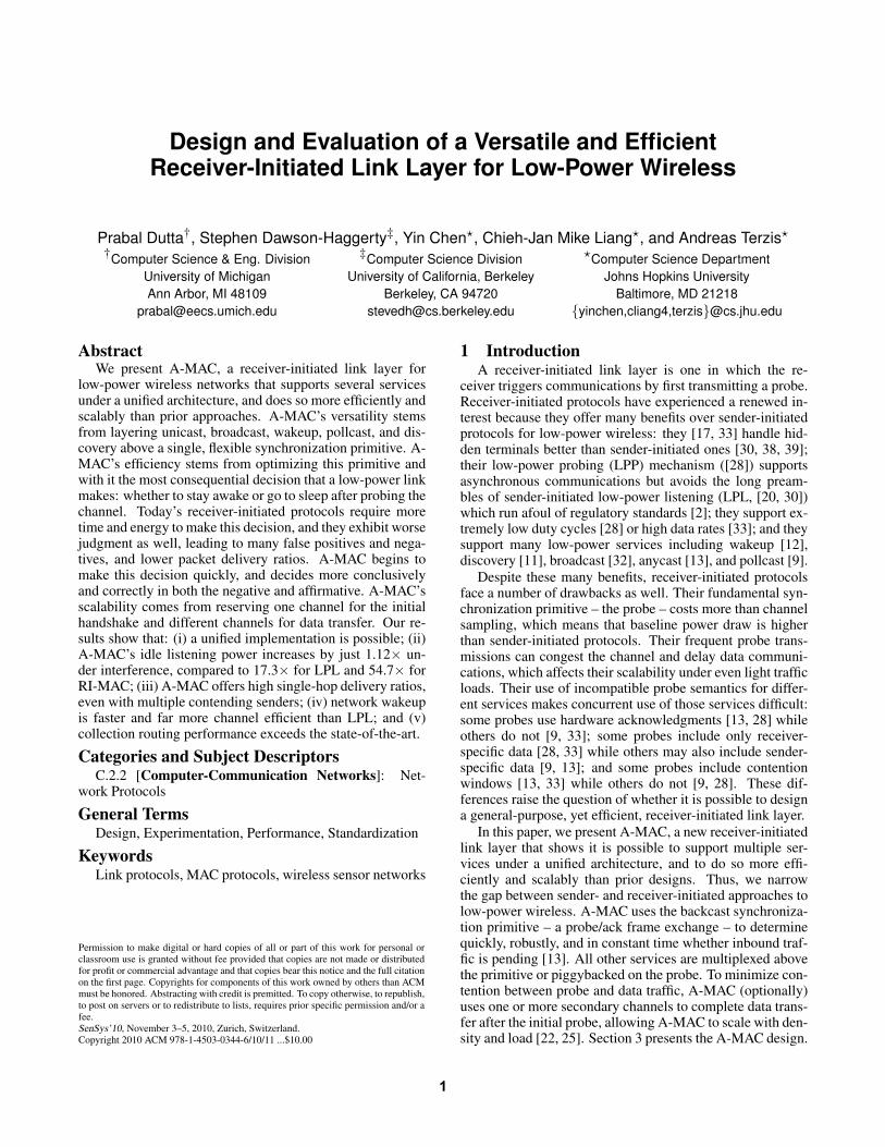
Figure 3. Example of an A-MAC unicast communicationshowing dynamic address changes and other frame fields.
We avoid the overreacting problem and design astandards-compliant unicast protocol as follows. Whensender S has pending traffic for receiver R, S enables hard-ware address recognition, enables its hardware auto-acks,and sets its hardware address to R+0x8000.3 Instead ofsending a probe to the broadcast address, receiver R sendsits probe to destination address R+0x8000 and requests anauto-ack. Sender S (as well as any other nodes with pendingtraffic to R) respond to the probe. If its probe is acknowl-edged, R remains awake to receive a frame while sender Sdoes not succumb to the overreacting problem.
Figure 3, shows a sender (Node 1) with traffic pendingfor the receiver (Node 2). The sender turns on its radio, setsits hardware address to 0x8002, enables hardware auto-acks,and begins to listen. At some later time, the receiver wakesup and sends a probe with a source address of 0x0002 and adestination address of 0x8002, and requests an acknowledg-ment. When the sender receives the probe frame, its radiogenerates an auto-ack. Upon detecting the beginning of theauto-ack, the receiver decides that an auto-ack frame may beincoming, so it continues to listen for at least 352 µs (or pos-sibly less if the data appear garbled) before turning off theradio. If a valid auto-ack is received, the receiver concludesthere is pending traffic for it, and it remains awake to receivethis data. At the same time, the sender transmits a data frame(after a short random delay comprising the contention win-dow) with a source address of 0x0001, a destination addressof 0x0002, and a locally-selected sequence number of 0x23,which is successfully received. The sender does not changeits radio hardware address for this transmission. The receiverthen prepares its next probe which explicitly acknowledgesthe preceding data frame by source address (0x0001) andsequence number (0x23). The sender turns off auto-acks ifit has no further data pending (or repeats this process if ithas more data), letting the receiver’s second probe go un-acknowledged, which allows the receiver to return to sleepafter a brief wait.4
3We reserve addresses with the high-order bit set for such use.4As an optimization, the receiver could acknowledge the
sender’s data frame, which the sender would use as a “hint” that itstransmission was successful (since hardware auto-acks only havesequence numbers but not source or destination addresses). Thisoptimization allows the sender to disable auto-acks prior to the re-
4.4 Broadcast CommunicationsBroadcast is a fundamental operation used by a wide
range of higher-layer services and applications. Neighbordiscovery, routing updates, and data dissemination all de-pend on a robust broadcast service for operation. A-MAC’sdesign of the broadcast service is identical to unicast commu-nications with one important difference. A sender S, simplydisables hardware address recognition altogether but keepshardware auto-acks enabled. Of course, this requires thatauto-acks be used exclusively for responding to probes (e.g.,they cannot be used to acknowledge data).
When a higher-layer service needs to send a broadcast,it sets the destination address of the frame to the broadcastaddress, e.g., 0xFFFF, and submits the frame to A-MAC fordelivery. When this frame is ready for transmission, A-MACdisables the hardware address recognition function of the ra-dio for at least as long as the probe period of its neighbors(or the longest of its neighbors’ probe periods, if differentneighbors are operating with different periods). During thistime, S will auto-ack every probe it receives, regardless ofthe probe’s actual destination address, and proceed to sendthe data packet like in the unicast case. Although this designdoes not violate the 802.15.4 standard, it clearly abuses thestandard in support of physical and link layer primitives thatthe standard was not originally designed to provide. Our goalis to show the feasibility of the A-MAC design using existinghardware, not that it is necessarily standards-compliant (al-though the latter is preferable, to allow it to be tested usingoff-the-shelf, standards-compliant hardware).
A common case that arises with this design is what to doif, while the broadcaster is listening for neighbors’ probes,the broadcaster’s own probe timer fires. Should it send theprobe and then return to listening or should it forgo the probeand continue listening? The A-MAC design chooses the firstapproach: a probe is transmitted when the probe timer fires.Doing so avoids a scenario we call the broadcast standoff inwhich two or more nodes that attempt to broadcast a packetwait patiently for the other(s) to first transmit a probe. TheA-MAC design avoids this situation, but it raises two fur-ther issues. First, the transmit and receive state machineswithin a node become more complex and cross-coupled.Second, while probing, a broadcaster may miss other neigh-bors’ probes, thereby reducing broadcast reliability.
A potential issue with our design is that if hardware auto-acks are used to acknowledge data frames as well as probes,then a broadcaster would inadvertently acknowledge everysingle data frame it received, signaling that the data weresuccessfully received when in fact it may not have actu-ally been received. Our unicast implementation avoids thisproblem by reserving hardware auto-acks exclusively for ac-knowledging probes. Data frames are acknowledged by in-cluding the acknowledgment information in the next probe.
ceiver’s next probe transmission, eliminating a race condition inwhich sender has to check the contents of the receiver’s secondprobe to decide whether to acknowledge it. The sender still waitsfor the receiver’s second probe to verify the hint by checking thatthe second probe’s sequence number and source address matchsender’s previous frame. However, this approach is incompatiblewith broadcasting, as we describe in § 4.4.
5

P ANode 2
Node 3
Node 4
P ANode 1
Node 5
Listen
Listen P A Listen P A Listen
P A Listen
Listen
P A
P A
Listen P A
P
P
A
A
Backcast
DST=0xFFFF
SRC=0x0002
DST=0xFFFF
SRC=0x0003
DST=0xFFFF
SRC=0x0004
DST=0xFFFF
SRC=0x0005
Figure 4. Asynchronous network wakeup with A-MAC.Although Nodes 2, 3, and 4 all ACK Node 5’s queryprobe, the ACK collision is non-destructive, and Node 5remains awake to communicate.
4.5 Asynchronous Network WakeupWaking up a multihop network of duty cycled nodes is a
fundamental problem in sensor networks. Applications as di-verse as interactive data collection, exceptional event detec-tion, and target tracking require nodes to wake up neighborsor even the entire network in response to an asynchronousevent. In many such applications, nodes will remain asleepfor long periods of time and so they are likely to lose syn-chronization. Ideally, the nodes would wake up only in re-sponse to external events or user queries, but would other-wise remain asleep. In the case of mobile sensors, nodesmay only need to communicate when they have data to up-load. However, it is still useful to be able to wake up a mobilenode to issue it a command or query.
Several techniques have been proposed for asynchronousnetwork wakeup in a low-power setting including variousforms of flooding and dissemination, but these techniqueshave poor channel efficiency, exhibit logistic-like perfor-mance in that they start and end slowly, or are designedwith the assumption that nodes are synchronized. As a re-sult, none of these techniques are ideally suited to the low-power, asynchronous network wakeup problem. In this sec-tion, we discuss two approaches to designing a backcast-based wakeup service – one that can work with standards-compliant radios and one that cannot. They exhibit highchannel efficiency, achieve the lower bound on wakeup time,and do not assume synchronization.
Figure 4 shows the first approach. In this figure, all nodescease periodic communications like routing beacons and in-stead operate at a very low duty cycle. The nodes wake up in-frequently, perhaps once every ten seconds or each minute, tocheck if any of their neighbors requires them to stay awake,by sending a probe to the broadcast address. Node 1 ini-tiates an asynchronous network wakeup by configuring itsradio to acknowledge all frames. After some time, Node 2sends a probe. Node 1 auto-acks this probe and Node 2 staysawake. This process repeats with Node 2 waking up Node 3and Node 4. However, when Node 5 wakes up, all of itsneighbors – Nodes 2, 3, and 4 – are already awake and theyall simultaneously auto-ack Node 5’s probe, which Node 5correctly decodes as a valid frame and hence remains awake.
Node 2
(Receiver)
Node 3
(Sender)
Node 1
(Sender)PredEvent
PredEvent
Pred
Listen
MAC=0x8765
Listen
MAC=0x8765
Listen
P A
P A
P A
Backcast
DST=0xFFFF
SRC=0x0002
PRED=elephantMAC=0x8765
Event
DST=0x8765
Figure 5. Pollcast implemented using the A-MAC archi-tecture. All nodes observe an “elephant sighting” event.Node 2 wishes to corroborate this observation with itsneighbors. It uses backcast to efficiently determine if anyneighbor also observed this event.
Transmitting to the broadcast address with the acknowl-edgment request bit set does not comply with the 802.15.4standard (and hence only works with the CC2420). One wayto sidestep the issue is to send the probe to a reserved wakeupaddress rather than the broadcast address. This leads to awakeup phase, in which a node first performs wakeup for onecycle, and then engages in normal communications. This ap-proach may be preferred since it also disentangles broadcastsand floods from wakeup, and is standards-compliant.
One problem common to both designs is that if anode misses the acknowledgments to its specially-addressedprobes during the network wakeup phase, then the node willremain asleep after the wakeup phase since its neighbors willno longer acknowledge specially-addressed probes. Thisproblem, too, can be avoided by using a special wakeup ad-dress and increasing the length of the probe frame so thatthe processor has enough time to: (i) read the address fromthe radio’s receive FIFO while the rest of the probe is beingreceived (i.e., pipelining the read and reception), (ii) checkif the address matches the special wakeup address, and (iii)instruct the radio to auto-ack the frame within the tight timewindow needed to generate a timely auto-ack. We do not ex-plore this idea any further in the context of network wakeup,but we do return to it in a more general form in the contextof Pollcast.
4.6 Pollcast Neighborhood QueriesDemirbas et al. recently proposed pollcast, a two-phase
primitive in which a node broadcasts a poll about the exis-tence of a node-level predicate P and then all nodes for whichP holds reply simultaneously [9]. The poller detects one ormore positive replies by sampling its radio’s Clear ChannelAssessment (CCA) signal which indicates whether the re-ceived signal strength exceeds a threshold. While pollcastoffers a novel approach to quickly calculate predicates, theproposed mechanism has some drawbacks, as their work ac-knowledges: simultaneous pollcasts within a two-hop neigh-borhood causes false positives (as would external interfer-ence). Selecting the CCA threshold presents a tuning chal-lenge since setting it too low causes false positives but settingit too high causes false negatives.
6

A-MAC provides a more robust architecture for im-plementing pollcast by mapping the original two-frame,query/response to a three frame operation. First, a singleframe transmission containing the predicate to be evaluatedis sent to the broadcast address, received by all neighbors,and evaluated. Next, a short time later, a probe is transmittedto a special address (contained in the first transmission). Fi-nally, the probe is acknowledged by all nodes for which thepredicate evaluated true.
Figure 5 illustrates an example in which all nodes ob-serve an event. Node 2 wishes to corroborate an “elephantsighting” event with its neighbors so it transmits a predicatedescribing the event, including a locally-generate ephemeralidentifier. The destination address of the predicate is 0xFFFF(broadcast), the source address is 0x0002, the predicate is’elephant’, and the ephemeral identifier is 0x8765. Node 2then waits for some time to allow Nodes 1 and 3 to receiveand evaluate the predicate. Node 2 then sends a probe des-tined to the ephemeral identifier 0x8765. Since both Node 1and Node 3 observed the same event, they both auto-ack theprobe, indicating the predicate was true. Note that althoughthe predicate is sent to the broadcast address, it does not needto be automatically acknowledged, so this approach is com-patible with 802.15.4 and A-MAC’s unicast and broadcast.
A drawback with this approach to pollcast is the need fortwo packet transmissions by the receiver: the first packetsends the predicate and the second packet sends the probe tothe ephemeral identifier. Ideally, the predicate could be pig-gybacked onto to the probe, eliminating the separate pred-icate transmission and its associated delay. The two chal-lenges with this approach include choosing the destinationaddress of the probe and ensuring that the predicate can beevaluated quickly enough (by the processor) to generate aproperly timed auto-ack. One option that we explore is tosend the probe to the broadcast address, piggyback the pred-icate on the probe, and pad the probe with a large payload.This allows a node to detect the beginning of the probe, readand evaluate just the predicate while the rest of the packet isbeing received, and enable hardware auto-acks before framereception completes. The pad bytes provide buffer time toevaluate the predicate before the 192 µs auto-ack timer fires.
4.7 Miscellaneous DetailsIn the current A-MAC implementation, each node
chooses its own probe schedule without any local or globalcoordination. If two nodes pick identical schedules, we relyon capture and contention for short-term progress, and clockdrift for long-term desynchronization. An improved im-plementation could use an explicit desynchronization proto-col like DESYNC [8]. When two nodes communicate, thesender caches the receiver’s probe period and phase. This al-lows the sender to minimize its radio on-time during subse-quent communications by listening just before the expectedprobe transmission. The cache holds four entries and uses anLRU eviction policy. An alternate policy might consider us-age frequency. Queued packets are transmitted round-robinfor fairness, but this can result in head-of-line blocking. AnEDF policy that orders pending packets by their receivers’probe times may be a better option, especially since currenthardware can only auto-ack one receiver’s probes at a time.
5 Backcast EvaluationBackcast is a critical primitive upon which A-MAC rests,
so we evaluate its reliability, efficiency, and performance un-der a range of conditions including carefully-controlled lab-oratory settings and more realistic indoor settings. Our re-sults show that backcast works on two different radios fromtwo different vendors, has a narrow range of failure cases,provides high energy- and channel-efficiency, and providesa strong foundation upon which to build the remaining linklayer services.
5.1 MethodologyWe use the Moteiv Tmote (Telos B) [31], Berkeley
Epic [14], and Crossbow Iris [7] motes for these experi-ments. We find that the backcast performance of both radiosis similar, so we only report detailed results for the CC2420radio. In the experiments that follow, signal strength is mea-sured by the radio over the first eight symbols of an acknowl-edgment (ACK) frame and reported as the received signalstrength indicator (RSSI) in dBm. Signal quality (LQI) isalso measured by the radio over the first eight symbols andis reported as a 7-bit unsigned integer that can be viewed asthe average correlation value or chip error rate (values near100 indicate an excellent link).
5.2 ACK Reception RobustnessWe first explore how delay differences in the path length
affect ACK reception rate. Figure 6(a) presents the setup forthis experiment. Two nodes, an initiator and a responder(both Tmotes) are connected to each other through a pair ofcirculators and a wireless channel emulator. A circulator isessentially an RF splitter that provides a low-loss RF path be-tween some terminals (1-to-2, 2-to-3, and 3-to-1) but a veryhigh-loss path between other terminals (1-to-3, 2-to-1, and 3-to-2). Circulators are used to split a single bi-directional RFpath into two unidirectional paths. We use the D3C2060 cir-culator from DiTom Microwave. A wireless channel emula-tor allows a complex RF environment, including attenuation,delay, fading, Doppler shift, and multipath, to be evaluatedin a laboratory setting. We use the Spirent SR5500 wirelesschannel emulator in these experiments. The SR5500 allowseach channel to be composed of several independent paths,each with its own delay and attenuation.
5.2.1 Effect of Path Delay DifferencesTo evaluate the effect of path delay difference on destruc-
tive intersymbol interference, the ACK channel from the re-sponder to the initiator (Channel 2) is split into two equalloss paths inside the channel emulator. The delay in the sec-ond path is swept from 0 to 1 µs in 10 ns steps. For eachdelay step, the initiator transmits 100 packets to the hard-ware broadcast address, at 125 ms intervals, and logs theRSSI, LQI, and sequence number of the resulting acknowl-edgments. The results are shown in Figure 6(b) and indicateintersymbol interference becomes destructive between 500and 600 ns, as expected. Note that a delay of 500 ns corre-sponds to a path delay difference of 150 m. Such path delaydifferences are rare in low-power wireless networks; linksare rarely more than tens of meters, so such significant delaydifferences would result in different received signal strengthvalues as well (unless transmission power control is used).
7

Wireless Channel Emulator
1
2
2
3
1 3
Circulator (2)
Cha
nnel
1
Cha
nnel
2
Responder
Faraday Cage
USB RFInitiator
(a) Experimental Setup
500 550 600 650 700 750 8000
0.1
0.2
0.3
0.4
0.5
0.6
0.7
0.8
0.9
1
Path Delay Difference (ns)
Pac
ket R
ecep
tion
Rat
e
(b) Intersymbol Interference
0.5 1 1.5 2 2.5 3 3.50
0.1
0.2
0.3
0.4
0.5
0.6
0.7
0.8
0.9
1
Path Power Difference (dB)
Pac
ket R
ecep
tion
Rat
e
(c) Power Capture
Figure 6. Figure (a) shows the experimental setup. Figure (b) shows the onset of destructive inter-symbol interference.Packet reception rate falls sharply as the delay difference in two paths exceeds 0.5 µs. Figure (c) shows the effect ofpower capture. When two frames collide, the first frame to arrive will be decoded correctly if its receive power is 3 dBhigher than the second frame.
LQI
HACK
74
78
82
86
90
94
98
102
106
1 4 7 10 13 16 19 22 25 28 31 34 37 40 43 46 49 52 55 58 61 64 67 70 73 76 79 82 85 88 91 94
Figure 7. The effect on LQI as the number of concurrent ACKs increases from 0 to 94 in a typical indoor deploymentsetting. The median value of LQI falls quickly for the first six nodes and then falls slowly. Beyond approximately 30nodes, the LQI values stabilize at approximately 100. The data suggest that even in the presence of a large number ofACK collisions, the receiver can successfully decode the ACK frame. Note the y-axis ranges from 74 to 106.
5.2.2 Effect of Path Loss
Power capture occurs when the received signal from onenode is sufficiently stronger than the sum of the received sig-nals from all other nodes [1]. To explore the effect of powercapture on backcast performance, the second path compo-nent in Channel 2 is delayed by 8,00 ns (1/2 of the 802.15.4symbol time). This base configuration ensures intersymbolinterference and, assuming equal path loss, results in destruc-tive interference and complete packet loss.
However, by adjusting the attenuation for the second path,from 0 to 3.5 dB, in 0.1 dB steps, the effect of power capturebecomes evident. The initiator receives the superposition oftwo (identical) frames, delayed by 8,000 ns, over a rangeof SINR values. The results show that when the first framearrives with 3 dB or higher power, it will be decoded consis-tently by the radio. The data also show a fairly linear transi-tion region between approximately 1 dB and 2.5 dB. Thesefigures establishes that power capture dominates (and ex-plains) the backcast phenomenon when the strongest ACK’spower exceeds the sum of the remaining ACKs by more thanapproximately 3 dB.
5.2.3 Large-Scale Performance
We now explore how backcast performs in a more realisticsetting – a university testbed. The testbed consists of Telos Bnodes and it is located in an office building with a typicalRF environment. For this experiment, 94 nodes within radiorange of an initiator are programmed to automatically ac-knowledge all probes. The 94 nodes are turned on, one afterthe other, and remain on for the rest of the experiment. Aftereach node is turned on, 500 frames are transmitted at 125 msintervals. This procedure generates a gradual increase in thenumber of auto-ack frame collisions. The LQI statistics areshown in Figure 7. The PRR is 100%.
The results show that the median value of LQI fallsquickly for the first six nodes and then falls slowly. Beyondapproximately 30 nodes, the LQI values stabilize at approxi-mately 100, although there are outliers. The data suggest thateven in the presence of a large number of ACK collisions, thereceiver can successfully decode ACK frames, even when nosingle ACK frame’s power dominates. The ACK receptionrate is nominally 100% (ACKs are received consistently, in-dependent of the number of concurrent transmissions).
8

0 5 10 15
0
5
10
15
20
Time (ms)
Cur
rent
(m
A)
(a) Probe
0 20 40 60 80
0
5
10
15
20
Time (ms)
Cur
rent
(m
A)
(b) Receive (Len=127 bytes)
590 600 610 620 630
0
5
10
15
20
Time (ms)
Cur
rent
(m
A)
(c) Transmit (Len=127 bytes)
0 200 400 600 800
0
5
10
15
20
Time (ms)
Cur
rent
(m
A)
(d) Idle (500 ms wait)
Primitive Cost (µJ)
Probe 253TX only 1578RX only 2670
CCA Check 194
(e) Primitive energy costs
0 0.5 1 1.5 20
200
400
600
800
1000
Probe period (s)
Ave
rage
cur
rent
(uA
)
(f) Probe
10−1
100
101
10210
2
103
104
Data period (s)
Ave
rage
cur
rent
(uA
)
(g) Receive
10−1
100
101
102
102
103
104
Data period (s)
Avera
ge c
urr
en
t (u
A)
AsynchronousScheduled
(h) Transmit
Figure 8. Link Power Model. Figures (a)-(c) show the Telos B mote’s instantaneous current draw for representativeasynchronous link primitives. Figure (d) shows the current draw when only listening (from 200 ms to 800 ms). Figure(e) shows the cost of each link primitive. Figures (f), (g), and (h) show the average current for probing, receiving, andtransmitting, respectively, as a function of the probe period Tprobe (f), and data period (g) and (h) with Tprobe = 0.5 s.
The data suggest that both constructive and destructiveinterference of the carrier signal occur. This result is notsurprising since the carrier signals are neither synchronizedin phase nor frequency across these 94 nodes. Rather, theyare generated locally by each node from a free-running crys-tal oscillator. The statistical superposition of an increasingnumber of signals does not lead to destructive interference,making backcast a robust synchronization primitive.
5.3 Energy MicrobenchmarksA-MAC services are built by combining a small set of
link primitives including probe, receive, transmit, and idle(listening for a probe). Figures 8(a)-8(d) show the traces ofthese primitives as well as their energy costs. The verticalline in Figure 8(c) indicates the point at which the sender’sradio signals that the probe’s start-of-frame delimiter (SFD)event has occurred. These data are collected by capturingthe voltage drop across a 10 Ω resistor in series with a 3 Vpower supply using a Tektronix TDS3014 digital storage os-cilloscope. Figure 8(e) summarizes the energy cost of eachbasic primitive. In all cases, other than probes, we use the802.15.4 link MTU frame size (127 byte payload).
Figure 8(f) shows how the average current due to probingcost scales with the probe period. Figure 8(g) shows howthe receive cost scales with data rate. Figure 8(h) showshow the transmit cost scales with data rate for both asyn-chronous communications (when the sender does not knowthe receiver’s probe schedule) and synchronous communica-tions (when the sender knows the receiver’s probe schedule).Figure 8 shows that A-MAC’s link primitives are more ex-pensive than in an optimized, commercial-grade LPL imple-mentation approach [22], but under the critical assumption ofno external interference. Section 5.4 explores what happenswhen this assumption is false.
Figure 9. A-MAC probe states and their energy con-sumption. Transitions of the lower line indicate statechanges. Total consumption is 263.56 µJ. Breakdown:(i) start (40.98 µJ); (ii) load probe (60.60 µJ); (iii) loaddone (22.7 µJ); (iv) probe alarm fired (re)send (6.31 µJ);(v) strobe and transmit (55.71 µJ); (vi) start ACK timer(29.86 µJ); (vii) send done ACK timeout (25.71 µJ); (viii)radio stop (8.78 µJ); and (ix) radio stopped (12.91 µJ).
Figure 9 shows the A-MAC probe’s power draw and as-sociated state transitions. In our implementation, the instru-mented probe consumes approximately 263 µJ. With radiohardware support, the following states would be eliminated:load probe, load done, probe alarm fired (re)send, and senddone ACK timeout. This would save about 115 µJ and re-duce the cost of the probe to approximately 148 µJ – lessthan three times the cost of an optimized LPL check [22].
9

0 500 1000 1500
0
5
10
15
20
Time (ms)
Cur
rent
(m
A)
(a) LPL sampling (no interfer-ence)
0 5 10 15
0
5
10
15
20
Time (ms)
Cur
rent
(m
A)
(b) LPL sample detail
0 1000 2000 3000
0
5
10
15
20
Time (ms)
Cur
rent
(m
A)
(c) LPL sampling (w/ interfer-ence)
0 50 100 150
0
5
10
15
20
Time (ms)
Cur
rent
(m
A)
(d) LPL overhearing detail
Figure 10. LPL preamble sampling techniques leave receivers susceptible to noisy wireless environments, such as thosecaused by 802.11 interference. Figures (a) and (b) show the macroscopic and microscopic behavior of the TinyOS 2.1sampling algorithm when the channel is clear: the receiver immediately returns to sleep. Figures (c) and (d) show themacroscopic and microscopic behavior while a file transfer is in progress using a nearby 802.11 access point. Of theseven channel samples visible in this trace, five are unnecessarily lengthened due to channel noise.
5.4 Robustness to External Interference
A basic problem with LPL and LPP systems that employRSSI to detect the presence of incoming traffic is that theysuffer from many sources of false alarms including inter-ference, overhearing, and collisions. Recent research hasdemonstrated the cost of external interference on the effec-tive duty cycle of LPL protocols. The results show that sig-nificant differences can exist between the expected and ac-tual duty cycles [4, 16]. We repeat similar experiments toquantify the effects of interference on MAC layer operationand energy consumption.
Table 1 shows the results of an experiment in which wemeasure the receiver’s idle listening current in an office en-vironment using three different synchronization schemes,TinyOS 2.1 LPL, RI-MAC LPP, and A-MAC LPP, under twodifferent interference workloads (with and without a nearby802.11 file transfer in progress). Although the TinyOS LPLtechnique performs better under ideal conditions, it degradesdramatically in the presence of interference, increasing av-erage current draw by a factor of 17.3 compared to the idlelistening case. The RI-MAC LPP technique performs evenworse, exhibiting an increase in idle current by a factor of54.7. A-MAC, in contrast, exhibits a nearly negligible 1.12×increase in current draw, demonstrating the backcast’s re-silience to false positives. For completeness, we also includereported figures for Hui’s MAC [22] which uses 54 µJ persample (54 µJ / (3 V × 0.5 s) = 36 µA). We estimate thepower draw is doubled in the presence of external interfer-ence (and equals the reported overhearing cost).
Figure 10 illustrates in detail how the preamble samplingtechniques used in LPL protocols leave receivers suscepti-ble to noisy wireless environments, such as those caused by802.11 interference during beaconing, file transfers, or au-dio/video streaming. Figure 10(a) shows the current drawover time when the channel is clear and Figure 10(b) showsthe detailed current draw of one channel sample. Fig-ure 10(c) shows the current draw of the same system whilea file transfer is in progress using a nearby 802.11 accesspoint. Of the seven channel samples in this trace, five are ofextended length due to channel noise. Figure 10(d) showsthe details of an extended sample.
Primitive w/o 802.11 w/ 802.11 IncreaseOperation interference interference in Current
TinyOS LPL 175 µA 3,030 µA 17.3×RI-MAC LPP 383 µA 12,576 µA 54.7×A-MAC LPP 206 µA 230 µA 1.12×
Hui LPL 36 µA† 72 µA‡ 2.0ׇ
Table 1. The effect of interference on idle listening cur-rent. The average current draw of three different syn-chronization schemes under no-load conditions and a500 ms check/probe interval. Results are the average offive samples, each one minute long. Although the LPL ex-hibits the lowest power under ideal conditions, both theTinyOS LPL and RI-MAC LPP exhibit dramatic powerincreases under interference while A-MAC’s LPP mech-anism shows a relatively negligible increase which showsA-MAC’s low-power probing is resilient to false positives.Hui’s LPL reported figure (†) is included for comparisonand our estimate of its interference current is noted (‡).
The extended channel sample in Figure 10(d), termed“delay-after-receive-check,” improves communications reli-ability. Shorter delays work under ideal circumstances but innoisy or congested environments, they lead to failed commu-nications [27]. The 100 ms delay-after-receive-check, when-ever channel energy is detected, substantially reduces LPLdelivery failure (a false negative). A-MAC is largely immuneto this problem because it uses an explicit probe rather thanan implicit channel energy signal. We hypothesize the Hui’sMAC is also more robust than the default TinyOS LPL due toits use of an explicit chirp, but lacking access to it, we couldnot verify this thesis. An open question is to further explorethe complex relationship between duty cycles, delivery ra-tios, false positives, false negatives, and latency as channelsample time is adjusted after a “busy” channel assessment.These results show the challenge of predicting network life-time based only on a model of the data workload, but withouta good model of the environmental factors. Although over-hearing and interference are well-known problems, these re-sults suggest they deserve further study.
10

MAC No. of SendersPacket Delivery RatioAvg Min Max
RI-MAC
1 99.9% — —2 97.5% 97.3% 97.7%3 95.6% 95.0% 96.8%4 90.7% 90.3% 90.9%
A-MAC
1 99.9% — —2 99.3% 98.2% 100%3 99.3% 98.3% 99.5%4 98.5% 96.7% 99.5%
Table 2. Packet delivery ratios for 1 through 4 distinctsenders transmitting to a single receiver. The packet in-terval on each sender is uniformly drawn from 0.5 to1.5 s, so on average, it is 1 pkt/s from each sender. Thereceiver uses a Tprobe =1 s. Senders attempt to send oneach probe to stress the contention algorithms, for 1,000packets. The largest difference between the maximumand minimum success rates for A-MAC is 2.8%, showingthat A-MAC provides fairness under modest contention.
6 Macrobenchmark EvaluationOur evaluation thus far has focused on microbenchmarks
comparing the time, energy, false positives, and false neg-atives of TinyOS LPL, RI-MAC, and A-MAC primitives.We now explore several macrobenchmarks to explore howlow-level power and performance improvements translate tohigh-level performance for several link layer services. Forthese experiments, we use the standard TinyOS 2.1 distribu-tion’s default LPL MAC and the RI-MAC [33] source code,which was provided by its authors.
6.1 Multiple Contending Unicast FlowsIt is well known that receiver-initiated MAC schemes han-
dle contending flows and hidden terminals much better thanlow-power, sender-initiated ones [6, 17, 33]. We now eval-uate how well A-MAC handles multiple contending flows.Table 2 shows between one and four senders contending totransmit to a single receiver for both RI-MAC and A-MAC.In this experiment, the receiver sends a probe, the sendersmay all auto-ack the probe concurrently, and then they con-tend for the channel. The receiver resends a probe after ei-ther each successful transmission or after receiving an auto-ack, but no data. The receiver sends up to a total of fiveprobes before stopping. Each probe doubles the size of thecontention window. The base contention window size is 20jiffies (610 µs). Each node transmits 1,000 packets.
The data in Table 2 show that A-MAC matches RI-MAC’sperformance for a single transmitter but performs better thanRI-MAC when additional senders begins to contend. Thelargest min-max difference is 2.8%, showing that even whenfour nodes are contending, A-MAC is fair.
6.2 Multiple Parallel Unicast FlowsWe now evaluate how well A-MAC supports multiple
concurrent flows between distinct pairs of senders and re-ceivers that are all located in a single collision domain.This experiment tests A-MAC’s multichannel optimizationin which the probe and acknowledgment are transmitted ona shared control channel, but data transfer may occur on a
WL Tx:Rx Probe Rate Pkts Time PDR(#) (ratio) (ms) (pkt/s) (#) (s) (%)
3 1:1 512 48.4 8,010 164 1003 1:1 128 71.9 8,056 112 1003 2:2 128 78.7 5,982 76 99.2
78.9 5,365 68 99.41 2:2 128 27.8 1,895 68 98.9
58.9 3,535 60 99.96 2:2 128 74.7 5,975 80 99.2
77.0 6,007 78 99.36 3:3 128 88.9 4,912 60 99.3
80.7 4,834 60 99.385.0 5,098 60 99.4
1 3:3 128 22.1 1,324 60 97.030.8 1,845 60 98.336.5 2,219 59 99.3
Table 3. A-MAC performance with multiple parallel uni-cast flows. Throughput and packet delivery ratio im-prove with additional channels. Even without the multi-channel optimization, A-MAC can sustain multiple, par-allel unicast flows located in the same collision domain.
different channel as stipulated in the probe. Table 3 showsA-MAC throughput and packet delivery ratio as a functionof the number of different whitelisted channels that are avail-able for use, the number of sender:receiver pairs transferringdata concurrently, and the receivers’ probe interval.
WL refers to the number of channels in the whitelistwhere WL=1 means all traffic happens on the control chan-nel (25), WL=3 means channels 15, 21, and 24 are in thewhitelist, and WL=6 means channels 11, 15, 20, 21, 24, and26 are in the whitelist. Tx:Rx identifies the number of inde-pendent transmitter:receiver pairs concurrently transmitting.The Probe field specifies the probe interval. The throughput(Pkt/s), data size (#Pkts), transfer time (Time), and packetdelivery ratio (PDR) are shown. The data show that through-put improves significantly with additional channels while the(already high) packet delivery ratio improves slightly withadditional channels.
6.3 Asynchronous Network WakeupA network wakeup is a special case of flooding or dis-
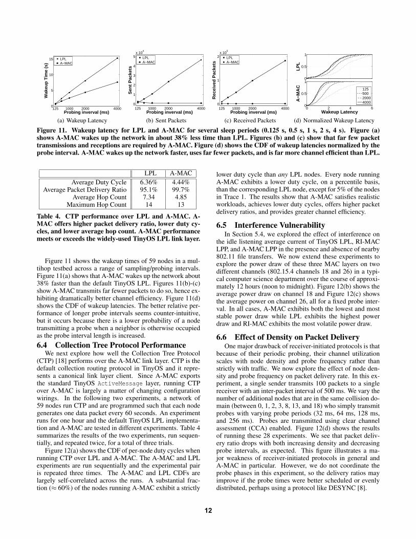
semination in which the goal is to ensure that every nodein the network receives a wakeup message. Prior work hasshown that LPL-based flooding techniques can cause sig-nificant contention and can use the radio channel (a scarceresource) over an extended period of time to complete aflood [26]. Figure 11 explores how well the TinyOS 2.1 LPLand A-MAC wakeup implementations of asynchronous net-work wakeup compare. In this experiment, the LPL wakeupalgorithm is a simple flood: the source of the flood repeatedlyresends a wakeup packet for slightly longer than the sleep in-terval. Every node that receives the packet also retransmitsit, after it detects a clear channel. The A-MAC flooding algo-rithm is a recursive broadcast without subsequent data packettransmissions. Since network wakeup is a special case offlood, this experiment also establishes A-MAC’s broadcastperformance.
11
125 1000 2000 40000
5
10
15
Probing inverval (ms)
Wak
eup
Tim
e (s
)
LPLA−MAC
(a) Wakeup Latency
125 1000 2000 40000
1
2
3
4
5x 10
4
Probing inverval (ms)
Sen
t Pac
kets
LPLA−MAC
(b) Sent Packets
125 1000 2000 40000
1
2x 10
5
Probing inverval (ms)
Rec
eive
d P
acke
ts
LPLA−MAC
(c) Received Packets
0
0.5
1
LPL
0 2 4 60
0.5
1
Wakeup Latency
A−M
AC
12550020004000
(d) Normalized Wakeup Latency
Figure 11. Wakeup latency for LPL and A-MAC for several sleep periods (0.125 s, 0.5 s, 1 s, 2 s, 4 s). Figure (a)shows A-MAC wakes up the network in about 38% less time than LPL. Figures (b) and (c) show that far few packettransmissions and receptions are required by A-MAC. Figure (d) shows the CDF of wakeup latencies normalized by theprobe interval. A-MAC wakes up the network faster, uses far fewer packets, and is far more channel efficient than LPL.
LPL A-MAC
Average Duty Cycle 6.36% 4.44%Average Packet Delivery Ratio 95.1% 99.7%
Average Hop Count 7.34 4.85Maximum Hop Count 14 13
Table 4. CTP performance over LPL and A-MAC. A-MAC offers higher packet delivery ratio, lower duty cy-cles, and lower average hop count. A-MAC performancemeets or exceeds the widely-used TinyOS LPL link layer.
Figure 11 shows the wakeup times of 59 nodes in a mul-tihop testbed across a range of sampling/probing intervals.Figure 11(a) shows that A-MAC wakes up the network about38% faster than the default TinyOS LPL. Figures 11(b)-(c)show A-MAC transmits far fewer packets to do so, hence ex-hibiting dramatically better channel efficiency. Figure 11(d)shows the CDF of wakeup latencies. The better relative per-formance of longer probe intervals seems counter-intuitive,but it occurs because there is a lower probability of a nodetransmitting a probe when a neighbor is otherwise occupiedas the probe interval length is increased.
6.4 Collection Tree Protocol PerformanceWe next explore how well the Collection Tree Protocol
(CTP) [18] performs over the A-MAC link layer. CTP is thedefault collection routing protocol in TinyOS and it repre-sents a canonical link layer client. Since A-MAC exportsthe standard TinyOS ActiveMessage layer, running CTPover A-MAC is largely a matter of changing configurationwirings. In the following two experiments, a network of59 nodes run CTP and are programmed such that each nodegenerates one data packet every 60 seconds. An experimentruns for one hour and the default TinyOS LPL implementa-tion and A-MAC are tested in different experiments. Table 4summarizes the results of the two experiments, run sequen-tially, and repeated twice, for a total of three trials.
Figure 12(a) shows the CDF of per-node duty cycles whenrunning CTP over LPL and A-MAC. The A-MAC and LPLexperiments are run sequentially and the experimental pairis repeated three times. The A-MAC and LPL CDFs arelargely self-correlated across the runs. A substantial frac-tion (≈ 60%) of the nodes running A-MAC exhibit a strictly
lower duty cycle than any LPL nodes. Every node runningA-MAC exhibits a lower duty cycle, on a percentile basis,than the corresponding LPL node, except for 5% of the nodesin Trace 1. The results show that A-MAC satisfies realisticworkloads, achieves lower duty cycles, offers higher packetdelivery ratios, and provides greater channel efficiency.
6.5 Interference VulnerabilityIn Section 5.4, we explored the effect of interference on
the idle listening average current of TinyOS LPL, RI-MACLPP, and A-MAC LPP in the presence and absence of nearby802.11 file transfers. We now extend these experiments toexplore the power draw of these three MAC layers on twodifferent channels (802.15.4 channels 18 and 26) in a typi-cal computer science department over the course of approxi-mately 12 hours (noon to midnight). Figure 12(b) shows theaverage power draw on channel 18 and Figure 12(c) showsthe average power on channel 26, all for a fixed probe inter-val. In all cases, A-MAC exhibits both the lowest and moststable power draw while LPL exhibits the highest powerdraw and RI-MAC exhibits the most volatile power draw.
6.6 Effect of Density on Packet DeliveryOne major drawback of receiver-initiated protocols is that
because of their periodic probing, their channel utilizationscales with node density and probe frequency rather thanstrictly with traffic. We now explore the effect of node den-sity and probe frequency on packet delivery rate. In this ex-periment, a single sender transmits 100 packets to a singlereceiver with an inter-packet interval of 500 ms. We vary thenumber of additional nodes that are in the same collision do-main (between 0, 1, 2, 3, 8, 13, and 18) who simply transmitprobes with varying probe periods (32 ms, 64 ms, 128 ms,and 256 ms). Probes are transmitted using clear channelassessment (CCA) enabled. Figure 12(d) shows the resultsof running these 28 experiments. We see that packet deliv-ery ratio drops with both increasing density and decreasingprobe intervals, as expected. This figure illustrates a ma-jor weakness of receiver-initiated protocols in general andA-MAC in particular. However, we do not coordinate theprobe phases in this experiment, so the delivery ratios mayimprove if the probe times were better scheduled or evenlydistributed, perhaps using a protocol like DESYNC [8].
12

00.250.5
0.751
Tra
ce 1
00.250.5
0.751
Tra
ce 2
0 0.05 0.1 0.15 0.2 0.25 0.30
0.250.5
0.751
Duty Cycle
Tra
ce 3
LPL
A−MAC
(a) CDF of CTP Duty Cycles
12 14 16 18 20 22 240
5
10
Time (hour of day)
Av
era
ge
Po
we
r (m
W)
A−MAC
RI−MAC
LPL
(b) Interference Effects (Ch. 18)
12 14 16 18 20 22 240
5
10
Time (hour of day)
Av
era
ge
Po
we
r (m
W)
A−MAC
RI−MAC
LPL
(c) Interference Effects (Ch. 26)
0 5 10 15 200
0.2
0.4
0.6
0.8
1
Number of additional nodes in cell
Packet
delivery
rate
32ms
64ms
128ms
256ms
(d) Effect of Density
Figure 12. Macrobenchmarks and statistics for (a) collection routing duty cycles, (b) and (c) power draw vs. extantenvironmental interference (co-channel communications), and (d) effect of neighborhood on packet delivery ratios.
7 DiscussionIn this section, we outline how future radio hardware
could improve A-MAC performance and discuss some of thelimitations that are fundamental to this design.
7.1 Future Hardware SupportA handful of radio enhancements could improve the per-
formance and energy efficiency of both the backcast prim-itive and the link layer services multiplexed above it. Themain bottlenecks in our current design occur from the limitedprocessor-radio bandwidth. Since backcast-based communi-cations requires multiple loads and unloads of the transmitand receive FIFOs, respectively, they are often the criticalpath operations that occur over a slow serial bus. If eitherhardware support for backcast existed inside the radio, orA-MAC was implemented in a processor with a memory-mapped radio [24, 35], the loads and unloads could be mademore efficient. Based on Figure 9, we estimate that simplehardware support would reduce the probe energy cost from263 µJ to 148 µJ, reducing idle listening power by 40%.
Under the current unicast design, a sender S sets it lo-cal address to R+0x8000, where R is the receiver’s hardwareaddress. As a result, S cannot concurrently acknowledgeprobes from a different receiver, R′, for which it also haspending traffic. Richer support for hardware address recog-nition in the radio would allow a sender to multiplex listen-ing for a probe. For example, a radio could filter for multiplesource or destination addresses in parallel. Some radios, likethe TI CC2520 [36], can already filter frames on up to twelvedifferent source addresses but these frames must be sent to aunicast destination address (meaning some of the approachesoutlined in this paper will not benefit). More flexible ad-dress recognition and auto-ack support would greatly reducethe processor burden and offer better efficiency than modernLPL protocols.
7.2 LimitationsThere are two fundamental limitations to A-MAC. First,
since A-MAC is a receiver-initiated protocol, the channelmust be probed periodically. This makes A-MAC fun-damentally less channel efficient under no-data conditionsthan sender-initiated protocols that listen quietly when notraffic is present. In other words, A-MAC channel usagescales with neighbor density and not necessarily with traf-fic. Hence, A-MAC may be incompatible with networksthat have high node density, short communication latency,or low-probability of detection requirements.
The first two issues are partly addressed by using a differ-ent channel for the probes and auto-acks than for the actualdata transmissions, since the initial probes can be sent on acontrol or pilot channel. The latter issue is more severe: A-MAC is fundamentally at odds with stealthy networks sincenodes cannot just listen quietly.
The second fundamental limitation with this approach isthat A-MAC’s primitive operation, a channel probe, is in-herently more expensive than the channel sample primitivein sender-initiated protocols. Sending a probe frame andlistening for an acknowledgment will always require moretime than sampling the channel. However, the benefits of us-ing backcast, namely its fixed energy cost, low false alarmrate, and efficient multiplexing ability, underscore a famil-iar theme in systems and networking research: optimal solu-tions that work well over a narrow range often perform morepoorly over the diversity of workloads observed in practice.
8 Conclusion
Optimizing performance for a narrow range of operat-ing conditions or isolated performance metrics is often rela-tively straightforward. For example, designing protocols thatachieve low power or high throughput under ideal conditionsis easy. It is more difficult to find general solutions that workwell across a broad spectrum of workloads and externalities.
In this paper, we present A-MAC, the first receiver-initiated link layer that concurrently supports unicast, broad-cast, wakeup, and pollcast services. Despite its generality, A-MAC achieves high channel efficiency, is resilient to a widerange of external interference and noise, offers high packetdelivery ratios across a wide range of workloads includingn-to-1 incast and multiple parallel flows, offers lower powerthan prior receiver-initiated protocols, and leverages multi-channel optimizations. We achieve these results using ex-isting radios in novel ways, but we note that performancewould improve with even a modicum of hardware support.
This work establishes that there is still plenty of room atthe MAC layer to improve duty cycles, achieve predictableoperation, offer high channel efficiency, and provide bettersupport for bursty workloads. This work paves the way fornew research in the design of radio hardware, MAC sub-layer primitives, MAC-layer services, and performance stud-ies to assess the utility and performance of this approach foremerging needs, like the 802.15.4(e) working group’s searchfor a low-power, channel efficient, asynchronous link layer.
13

9 Acknowledgments
Special thanks to Razvan Musaloiu-E. for help in de-veloping and evaluating a preliminary A-MAC prototype,Steven Lanszisera for help with modulation schemes and ra-dio receiver architectures, Rabin Patra for help with wirelesschannel emulation, Intel Labs Berkeley for allowing us ac-cess to their laboratory, the anonymous reviewers for theirinsightful feedback, and Alberto Cerpa for shepherding thispaper. This material is based upon work partially supportedby the National Science Foundation under grants #0964120,#0435454, #0454432, #0546648, #0834470, and #0627611,as well as a Microsoft Research Graduate Fellowship.
10 References[1] J. Arnbak and W. van Blitterswijk. Capacity of slotted ALOHA in
rayleigh-fading channels. IEEE Journal on Selected Areas in Communications,5(2):261–269, Feb 1987.
[2] Association of Radio Industries and Businesses (ARIB). ARIB STD-T67:Telemeter, Telecontrol, and Data Transmission Radio Equipment for SpecifiedLow-Power Radio Station, Version 1.1. ARIB STD-T67, 2005.
[3] Atmel. AT86RF230. Available at: http://www.atmel.com/dyn/products/product_card.asp?part_id=3941.
[4] C. A. Boano, T. Voigt, N. Tsiftes, L. Mottola, K. Roemer, and M. A. Zuniga.Making sensornet MAC protocols robust against interference. In EWSN’10:
Proceedings of the 7th European Conference on Wireless Sensor Networks, Feb.2010.
[5] M. Buettner, G. Yee, E. Anderson, and R. Han. X-MAC: A short preambleMAC protocol for duty-cycled wireless sensor networks. In Sensys’06:
Proceedings of the 4th International Conference on Embedded Networked
Sensor Systems, Nov. 2006.
[6] D. P. Connors and G. J. Pottie. Response Initiated Multiple Access (RIMA), aMedium Access Control protocol for satellite channels. In GLOBECOM’00:
Proceedings of the IEEE Global Telecommunications Conference, 2000.
[7] Crossbow. Wireless Module - IRIS 2.4GHz. Available at:http://www.xbow.com/Products/productdetails.aspx?sid=264.
[8] J. Degesys, I. Rose, A. Patel, and R. Nagpal. DESYNC: self-organizingdesynchronization and tdma on wireless sensor networks. In IPSN ’07:
Proceedings of the 6th International Conference on Information Processing in
Sensor Networks, pages 11–20, Apr. 2007.
[9] M. Demirbas, O. Soysal, and M. Hussain. A singlehop collaborative feedbackprimitive for wireless sensor networks. In INFOCOM’08: Proceedings of the
27th Conference on Computer Communications, Apr. 2008.
[10] A. Dutta, D. Saha, D. Grunwald, and D. Sicker. SMACK: a SMartACKnowledgment scheme for broadcast messages in wireless networks. InSIGCOMM’09: Proceedings of the ACM Conference on Data Communication,pages 15–26, Aug. 2009.
[11] P. Dutta and D. Culler. Practical asynchronous neighbor discovery andrendezvous for mobile sensing applications. In SenSys ’08: Proceedings of the
6th International Conference on Embedded Networked Sensor Systems, pages71–84, Nov. 2008.
[12] P. Dutta, D. Culler, and S. Shenker. Procrastination Might Lead to a Longer andMore Useful Life. In HotNets-VI: Proceedings of the 6th Workshop on Hot
Topics in Networks, Nov. 2007.
[13] P. Dutta, R. Musaloiu-E., I. Stoica, and A. Terzis. Wireless ACK collisions notconsidered harmful. In HotNets-VII: Proceedings of the 7th Workshop on Hot
Topics in Networks, Oct. 2008.
[14] P. Dutta, J. Taneja, J. Jeong, X. Jiang, and D. E. Culler. A building blockapproach to sensornet systems. In SenSys’08: Proceedings of the 6th
International Conference on Embedded Networked Sensor Systems, pages267–280, Nov. 2008.
[15] A. El-Hoiydi and J.-D. Decotignie. Low power downlink MAC protocols forinfrastructure wireless sensor networks. Mobile Networks and Applications,10(5):675–690, 2005.
[16] R. Fonseca, P. Dutta, P. Levis, and I. Stoica. Quanto: Tracking energy innetworked embedded systems. In OSDI’08: Proceedings of the 8th USENIX
Symposium on Operating Systems Design and Implementation, pages 323–338,Dec. 2008.
[17] J. J. Garcia-Luna-Aceves and A. Tzamaloukas. Reversing thecollision-avoidance handshake in wireless networks. In MobiCom ’99:
Proceedings of the 5th International Conference on Mobile Computing and
Networking, pages 120–131, Aug. 1999.
[18] O. Gnawali, R. Fonseca, K. Jamieson, D. Moss, and P. Levis. Collection TreeProtocol. In SenSys’09: Proceedings of the 7th International Conference on
Embedded Networked Sensor Systems, pages 1–14, Nov. 2009.
[19] S. A. Gronomeyer and A. L. McBride. MSK and offset QPSK modulation.IEEE Transactions on Communications, 24(8), 1976.
[20] J. Hill and D. Culler. Mica: A Wireless Platform for Deeply EmbeddedNetworks. IEEE Micro, 22(6):12–24, Nov. 2002.
[21] J. Hill, R. Szewczyk, A. Woo, S. Hollar, D. Culler, and K. Pister. Systemarchitecture directions for network sensors. In ASPLOS-IX: Proceedings of the
9th International Conference on Architectural Support for Programming
Languages and Operating Systems, Nov. 2000.
[22] J. W. Hui and D. E. Culler. IP is dead, long live IP for wireless sensor networks.In SenSys’08: Proceedings of the 6th International Conference on Embedded
Networked Sensor Systems, pages 15–28, Nov. 2008.
[23] IEEE Standard for Information technology – Telecommunications andinformation exchange between systems – Local and metropolitan area networks.Specific requirements – Part 15.4: Wireless Medium Access Control (MAC)and Physical Layer (PHY) Specifications for Low-Rate Wireless Personal AreaNetworks (LR-WPANs), May 2003.
[24] Jennic. Wireless Microcontrollers: JN5121 and JN513x. Available athttp://www.jennic.com/products/, 2007.
[25] C.-J. M. Liang, R. Musaloiu-E, and A. Terzis. Typhoon: A reliable datadissemination protocol for wireless sensor networks. In EWSN’08: Proccedings
of the 5th European Conference on Sensor Networks, Jan. 2008.
[26] J. Lu and K. Whitehouse. Flash flooding: Exploiting the capture effect for rapidflooding in wireless sensor networks. In INFOCOM’09: Proceedings of the
28th Conference on Computer Communications, Apr. 2009.
[27] D. Moss. Personal communications, 2010.
[28] R. Musaloiu-E., C.-J. Liang, and A. Terzis. Koala: Ultra-low power dataretrieval in wireless sensor networks. In IPSN’08: Proceedings of the 7th Intl.
Conference on Information Processing in Sensor Networks, Apr. 2008.
[29] S. Pasupathy. Minimum Shift Keying: A spectrally efficient modulation. IEEE
Communications Magazine, 1979.
[30] J. Polastre, J. Hill, and D. Culler. Versatile low power media access for wirelesssensor networks. In Sensys’04: Proceedings of the 2nd International
Conference on Embedded Networked Sensor Systems, Nov. 2004.
[31] J. Polastre, R. Szewczyk, and D. Culler. Telos: Enabling ultra-low powerwireless research. In IPSN’05: Proceedings of the 4th International Conference
on Information Processing in Sensor Networks, Apr. 2005.
[32] Y. Sun, O. Gurewitz, S. Du, L. Tang, and D. B. Johnson. ADB: an efficientmultihop broadcast protocol based on asynchronous duty-cycling in wirelesssensor networks. In Sensys’09: Proceedings of the 7th International Conference
on Embedded Networked Sensor Systems, pages 43–56, Nov. 2009.
[33] Y. Sun, O. Gurewitz, and D. B. Johnson. RI-MAC: a receiver-initiatedasynchronous duty cycle MAC protocol for dynamic traffic loads in wirelesssensor networks. In SenSys’08: Proceedings of the 6thth International
Conference on Embedded Networked Sensor Systems, pages 1–14, Nov. 2008.
[34] Texas Instruments. CC2420: 2.4 GHz IEEE 802.15.4 / ZigBee-ready RFTransceiver. Available athttp://www.chipcon.com/files/CC2420_Data_Sheet_1_3.pdf, 2006.
[35] Texas Instruments. CC2430: System-on-Chip Solution for 2.4 GHz IEEE802.15.4 / ZigBee. Available at http://www.ti.com/lit/gpn/cc2430, 2007.
[36] Texas Instruments. CC2520: Second generation 2.4 GHz IEEE 802.15.4 /ZigBee-ready RF Transceiver. Available athttp://www.ti.com/lit/gpn/cc2520, 2007.
[37] T. van Dam and K. Langendoen. An adaptive energy-efficient MAC protocol forwireless sensor networks. In SenSys’03: Proceedings of the 1st Intl. Conference
on Embedded Networked Sensor Systems, pages 171–180, Nov. 2003.
[38] W. Ye, J. Heidemann, and D. Estrin. An energy-efficient MAC protocol forwireless sensor networks. In INFOCOM’02: Proceedings of the 21st
Conference on Computer Communications, June 2002.
[39] W. Ye, F. Silva, and J. Heidemann. Ultra-low duty cycle MAC with scheduledchannel polling. In SenSys ’06: Proceedings of the 4th International Conference
on Embedded Networked Sensor Systems, pages 321–334, Nov. 2006.
14