design and fabrication of economical plastic injection...
TRANSCRIPT

Design And Fabrication of Economical Plastic Injection
Molding Machine
Group No:-27
Team No:-24255
Prepared By:-Sandip J. Patel (110780119007)
Ajay B. Patel (110780119113)
Vinesh S. Prajapati (110780119118)
Zeal N. Shah (120783119007)
Under The Valuable Guidance of
Prof A. G. Barad
Department of Mechanical Engineering (SRPEC)
1

OUTLINE
Project definition
Purpose of project
Project background
Working principle
Plastic materials
Work flow and plan work
Literature review
Required parts
Design calculation of parts
2

3
Part drawing
Various problems and solutions
ANSYS analysis
Advantages
Future scope
Conclusion
References

PROJECT DEFINITION
For small scale industry the requirement of semiautomatic plastic injection machine
demand with low cost day by day increasing so there is need of solution so our
project is based on design and development of economical plastic injection molding
machine for small industry.
4

WHY WE HAVE CHOOSENTHIS PROJET
5
High cost of machine for small scale industries
Use for small scale industries
Small and complex part produce
Less electricity consumption
Less space requirement
Improve production rate
Competitively less operation cost

PROJECT BACKGROUND
6
Now a days there are many methods to develop plastic parts like bottle caps,
mobile phone parts, electronic housings, containers, automotive interiors and
most other plastic products.
Molding process are industrial process in which plastic parts are created by
injection of molten metal in mould.
In the study of molding process the output quality is rather important. A significant
improvement in output quality may be obtained by machine which we are going to
be develop.
We reduce the machine cost by developing this machine. In project we gather lots
of important information from research papers and patents. According to that
research we design different components of machine.
WORKING PRINCIPLE
7

8
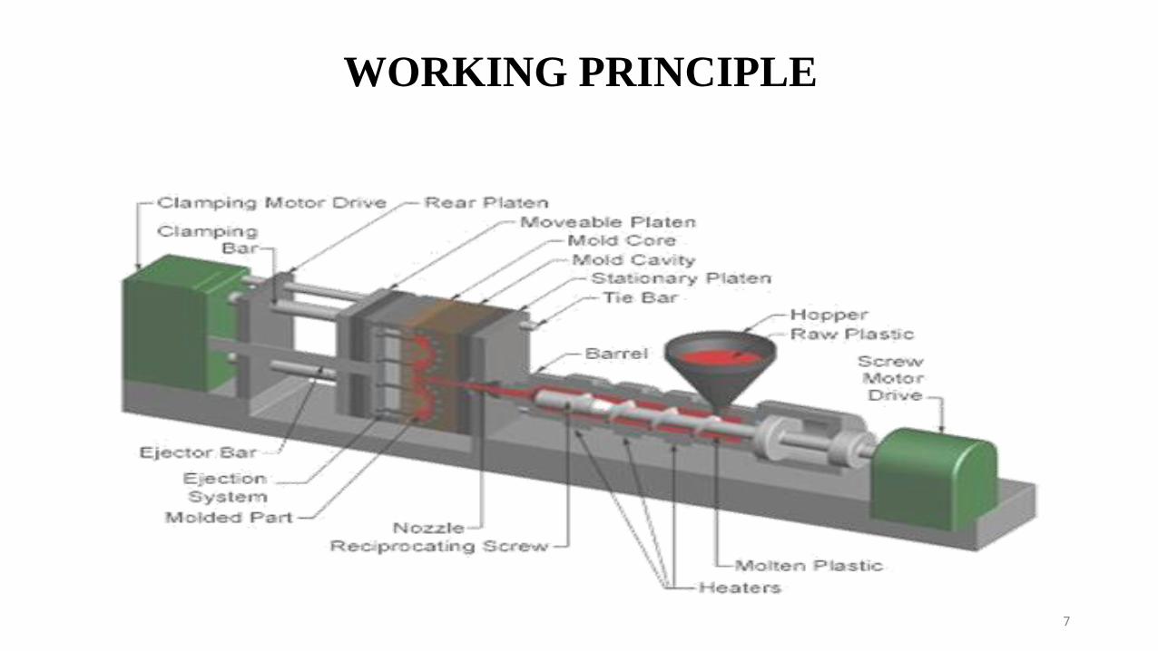
The injection unit is responsible for both heating and injecting the material into the
mould. The first part of this unit is the hopper, a large container into which the raw plastic
is poured. The hopper has an open bottom, which allows the material to feed into the
barrel. The barrel contains the mechanism for heating and injecting the material into the
mould. This mechanism is usually a ram injector or a reciprocating screw. A ram injector
forces the material forward through a heated section with a ram or plunger that is usually
hydraulically powered. Today, the more common technique is the use of a reciprocating
screw.
A reciprocating screw moves the material forward by both rotating and sliding axially,
being powered by either a hydraulic or electric motor. Injection moulding is an
economical and very efficient method of producing injection moulded parts. It can
produce millions of parts with exactly the same shape, dimension, and quality. Some
examples of injection moulded parts are the mobile phones, mouse, keyboard, and many
components found inside the automobile.

9
As the molten resin is being injected into the mould, it enters the mould opening called the
sprue. From the sprue this molten material will then be distributed to the runners then it
will be forced into the gate and then into the cavity. The cavity must be filled precisely to
avoid short shots but it must not be over packed (over packing is forcing more than
enough pressure to the resin and it can damage the mould).
The molten resin will stay in the cavity for 30 seconds to 1 minute or more until it cools
down and solidify. When the resins solidify a moulded part is formed. The mould will
open and then the moulded part will be ejected. The mould closes and its ready for another
shot.

10
Compression Molding
Transfer Molding
Injection Molding
PROCESSING METHODS
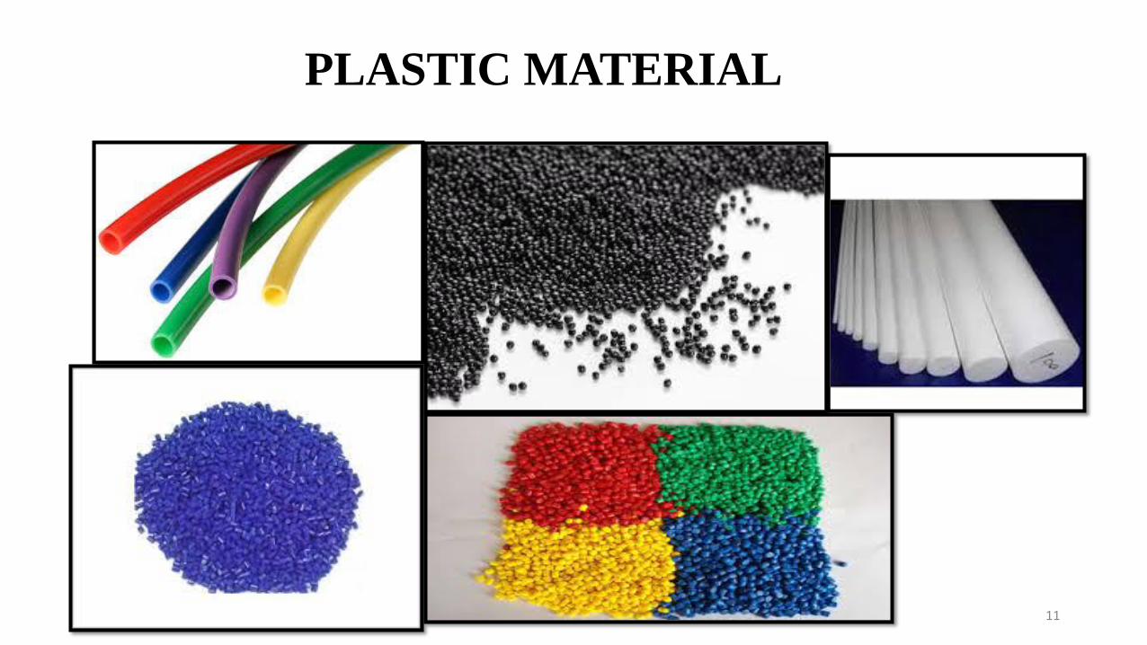
PLASTIC MATERIAL
11

I. Thermoplastics
II. Thermosetting plastics.
Thermoplastics:-Thermoplastics are the plastics that do not undergo chemical
change in their composition when heated and can be molded again and again. They
are easily molded and extruded into films, fibers and packaging. Examples include
polyethylene (PE), polypropylene (PP) and polyvinyl chloride (PVC).
Thermosetting plastics:-Thermosetting plastics which are formed by heat process
but are then set (like concrete) and cannot change shape by reheating. They are hard
and durable. Thermo sets can be used for auto parts, aircraft parts and tires.
Examples include polyurethanes, polyesters, epoxy resins and phenolic resins.
12
TYPES OF PLASTIC MATERIAL[w2]

THERMOPLASTIC PROPERTIES[w2]

14
THERMOSETTING PROPERTIES[w2]

15
POLYPROPYLENE MATERIAL
Polypropylene, a synthetic resin built up by the polymerization of propylene.
Polypropylene is molded or extruded into many plastic products in which toughness,
flexibility, light weight, and heat resistance are required.
Polypropylene (pp), also known as polypropene, is a thermoplastic polymer used in a
wide variety of applications including packaging and labeling, textiles (e.G., Ropes,
thermal underwear and carpets), stationery, plastic parts and reusable containers of
various types, laboratory equipment, loudspeakers, automotive components, and polymer
banknotes.
Polypropylene has a variety of different unique properties that makes it invaluable in
applications, where rigidity and stiffness are needed. As a result, polypropylene is used in
everything from plastic containers to wall siding laminates.[W6]
16
CHARACTERISTIC Light in weight
Excellent resistance to stress and high resistant to cracking (i.e. it has high tensile and
compressive strength)
High operational temperatures with a melting point of 160°C
Excellent dielectric properties
Non-toxic
Easy to produce, assembly and an economic material
It is often used in applications where rigidity and stiffness are needed. When polyethylene
is incapable of providing mechanical properties that are specified, in many cases, it is
polypropylene that takes its place. [w5]
17
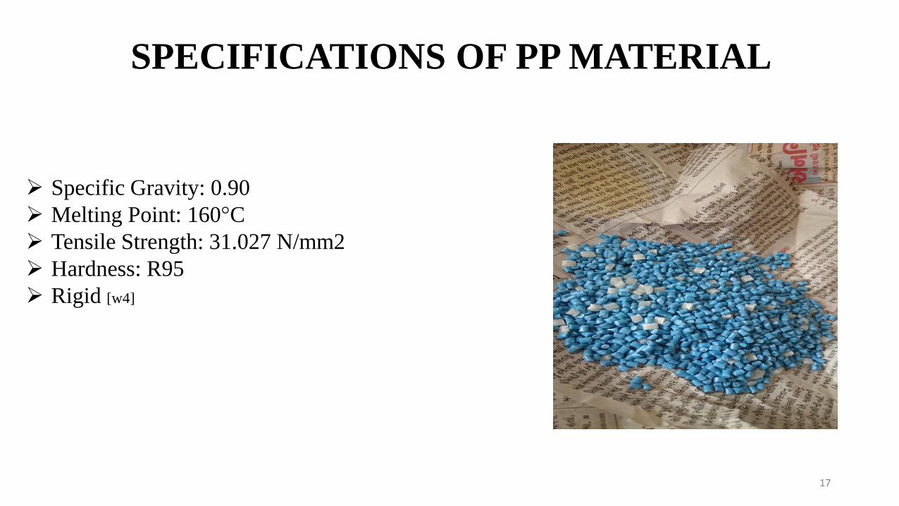
Specific Gravity: 0.90
Melting Point: 160°C
Tensile Strength: 31.027 N/mm2
Hardness: R95
Rigid [w4]
SPECIFICATIONS OF PP MATERIAL

18
start
Study of plastic injection moulding process
Market survey and problem definition
Study of research paper an literature review
List of required equipments
Design calculations of parts
Analysis of the frame
FLOW PROCESS CHART OF OUR PROJECT

19
Part modelling in software
Fabrication of parts
Assemble the parts in workshop
Perform experiment on machine with different temperature
Calculate the output parameters
Check quality of the output part
finish

July Aug. Sep. Oct. Nov. Jan. Feb. March April
1) Definition
2)Research paper
3) List of required
equipment
4) Part Design
5) Part drawing
6) Part fabrication
7) Assembly
WORK PLAN FOR PROJECT WORK
20

LITERATURE REVIEW
21

Sr. Title Investigator Remarks
1 Mechatronic Design And
Injection Speed Control of
An Ultra-high Speed Plastic
Injection Molding Machine
Ching-Chih Tsai,
Shih-Min Hsieh,
Huai-En Kao
In this work, pragmatic
techniques for mechatronicdesign and injection speedcontrol of an ultrahigh-speed plastic injectionmolding machine.
PI controller and a fuzzy PIcontroller are used,compared and thenimplemented into a digitalsignal processor (DSP) usingstandard C programmingtechniques.
22

Sr. Title Investigator Remarks
2 The microscopic features of
cavitation erosion and the
solution in the plastic
injection molding machines
William Liu The failure of nozzle unit in
the plastic injection
molding machines was
discovered to be cavitation
erosion, rather than
corrosion
Three types of erosion pits
in different size order have
been discovered
The cavitation erosion with
substituting stainless steel
to aluminum has been
successful
23

Sr. Title Investigator Remarks
3 Improvement of Injection
Molding Processes By
Using Dual Energy
Signatures
Egon Müller, Rainer
Schillig
This paper presents two
methods of dualising the
time and energy
consumption in the plastic
injection moulding process.
Based on the dual process
analysis, improvement
concepts are brought
forward. The value stream
mapping method can thus,
while maintaining its inner
logic, be extended to an
energy value stream
mapping method (EVSM).24

Sr. Title Investigator Remarks
4 CFD-based Predictive
Control of Melt
Temperature In Plastic
Injection Molding
A.G. Gerber, R.
Dubay, A. Healy
unique method of coupling
computational fluid dynamics
(CFD) to model predictive control
(MPC) for controlling melt
temperature.
The CFD to generate, via open-
loop testing, a temperature and
input dependent system model for
multi-variable control of a three-
heater barrel on an injection
molding machine.
CFD can be used to dramatically
reduce the time associated with
open-loop testing through physical
experiments.25

Sr. Title Investigator Remarks
5 A Simulation Test For The
Selection of Coatings And
Surface Treatments For
Plastics Injection Molding
Machines
S.J Bull, R.I
Davidson, E.H
Fisher, A.R McCabe,
A.M Jones
The Glass-filled polymers are
known to produce
considerable wear on the
screws and barrels of injection
molding machines and several
coatings and surface
treatments have been used.
They have developed a novel
wear tester to simulate the
conditions of wear which
occur in the barrel of an
injection molding machine.
The tester concept is similar to
that of the ASTM rubber
wheel abrasion test.26

Sr. Title Investigator Remarks
6 Analysis of Premature
Failure of a Tie Bar in an
Injection Molding
Machine
C. Sasikumar, S.
Srikanth, S.K. Das
Premature failure of a tie bar
made of AISI 4140 steel in a
150 tone plastic injection-
molding machine has been
analyzed. Although the nominal
tensile stress acting on the tie
bars (95.5 MPa) is far lower
than the yield strength of this
material (750–900 MPa).
The solution is a hydraulic
clamping mechanism rather
than a toggle clamp mechanism
for the mold will minimize the
cyclic strain on the tie rods.
27

Sr. Title Investigator Remarks
7 A New Approach to the
Optimization of Blends
Composition in Injection
Moulding of Recycled
Polymer
G. Lucchetta, P.F.
Bariani, W.A.
Knight
Recycled polymers are usually
blended with virgin polymers
to obtain the best trade-off
between cost and low melt
viscosity.
This last constraint is
necessary to avoid short shots
and to minimize the clamp
force of the required injection
molding machine and,
therefore, the process cost.
A new approach to the
minimization of the overall
manufacturing cost .
28

Sr. Title Investigator Remarks
8 Failure Analysis of H13
Working Die Used In
Plastic Injection
Molding
D. Papageorgiou,
C. Medrea, N.
Kyriakou
The die was made from AISI H13
steel and was intended for the
production of plastic cups used
for the outer closure of cylindrical
aluminum cans in coffee
packaging.
Corrosion damage and wide crack
are observed by necked eye.
Design deficiency and improper
cooling conditions generated a
complex fatigue-corrosion
cracking mechanism that lead to
the damage of the die after half of
it’s predicted service life.
29

Sr. Title Investigator Remarks
9 Barrel temperature control
during operation transition
in injection molding
Ke Yao, Furong Gao,
Frank Allgöwer
• Transitions between the
machine's idle state and the
operation state, significant
temperature variations exist in
the temperature zones.
• This leads to inhomogeneous
melt temperatures and
inconsistent product quality.
• A feedback controller and an
iterative learning feed forward
controller are implemented
and tested on an industrial-
sized reciprocating-screw
injection molding machine.
30

Sr. Title Investigator Remarks
10 Metallic powder injection
molding using low
pressure
Aparecido Carlos
Gonçalves
• PIM is a technology capable
of producing a new range of
components from powders.
• This advanced technology
overcomes the existent
limitations in the forming of
products with complex
geometry.
• The purpose of this work is to
review the metal injection
molding techniques and apply
the low pressure injection
molding process to family of
parts using metallic powder
with 10 μm particle size31

PARTS
Main frame
Radial gearbox
Barrel
Pushing Handle
Heating coil and regulator
Injection mechanism
die
Helical compression spring
Lead screw and vice
Hopper
bearing32

33
DESIGN CALCULATIONS OF PARTS
1. Design of shaft
2. Design of gear
3. Design of plunger
4. Design of barrel

34
3
3
3
3
16
16
tan16
41250 250
16
20
T
d
dT
dforce dis ce
d
d mm
Generally our hand can lift 25kg =250 N
Now,
So, the diameter of shaft is 20 mm
DESIGN OF SHAFT

DESIGN OF GEAR
35
Now, torque is given by
tT F d
Here, we assume V =8 m/sec (for ordinary cut gears)
1000
250 8
1000
2
tF V
kw
Power is 2 Kw.

36
By using Lewis equation
T d vW c b Y m
247.1 /d MN mm
b= face width of gear
Y=form factor = π×y
y=0.154-0.912/z (for 20˚ involute system)
y=0.0628
So, Y=0.198

37For standard value of module take m=3
36 2 10
47.1 10 0.27 10 0.1988
3.12
T
PW
V
m m
m
Take, V=8 m/sec, b= 10m
3.05
3.05
0.27
v
v
CV
C
For cast iron grade 20

38
Pitch circle diameter=3×10=30mm
Pitch=π×D/Z=10mm
Addendum=m=3mm
Dedendum=1.25m=3.75mm
Clearance= 0.25m=0.75mm
Working depth= 2m=6mm
Whole depth= 2.25m=6.75mm
Tooth thickness= 1.57m=4.71mm
Fillet radius= 0.4m=1.2mm
DATA OF GEAR

DESIGN OF PLUNGER
39
One rotation of handle=one rotation of gear
=no. of teeth × pitch
=10×10
Effective Length =100 mm
Diameter of the plunger:
Volume of plunger=volume of barrel
2
4
4
4 35
0.92 100
21
p e
p
e
p
p
md l
md
l
d
d mm

40
So, the diameter of the plunger is 21 mm.
Total length = 3 × Effective Length = 3 × 100
= 300 mm

DESIGN OF BARREL
41
Dia. of barrel = Dia. Of plunger + 1mm clearance
= 21 + 1
= 22 mm
External diameter of barrel = Dia. of barrel + 2×thickness of barrel
= 22 + 2(7)
= 36 mm
Internal dia. of barrel = dia. Of plunger + clearance
= 21 + 1
= 22 mm

42

43

44

45

46

47

48

49

50

51

52

53

54

55
ASSEMBLY

VARIOUS PROBLEMS AND SOLUTIONS
56
Die setting
Stop the molten material leakage in nozzle
For Diff. die different arrangement of injection mechanism

57
FRAME STRUCTURE

ANALYSIS OF FRAME
58

59

60

61

ADVANTAGES
Alternative for plastic cups and plates.
Cheaper and easily available material used.
Quick response
No fire hazard problem due to over loading.
Continuous operation is possible without stopping.
High production rate.
High tolerances.
Occupies less floor space.
Fastest cycle time incase of rubber, the rubber is warmed before going into the mold.
Little finishing part after injection.
Minimum scrap losses. 62

FUTURE SCOPE
63
Plastic injection moulding industry is now facing the very heavy competition; most of the
plastic injection moulding companies is working on mercy profits and low technologies.
Speed up all the moulding machines. For this point you need to be sure that your
machines are suitable for high speed running
Even if your machine are high speed, but if you are in shortage of automation system in
your injection moulding plants, then you need a lot of labour to pick up the moulded
plastic components from the machine and you need to stack or collect them before
packing. All these need labours and this will reduce the production capacity, in the same
time the labour cost will be highly increased.
In the project we have used manual plunger arrangement for pressing the molten plastic
instead of that we can have hydraulic arrangement for the automatic control that will
reduce production time.
Also for the batter and quick heating to melt the plastic insulation can be done which will
reduce the heat loss.

CONCLUSION
Due to it’s low cost, this working model can be successfully inducted in small scale
molding units and can be used to manufacture small plastic component at an
acceptable cycle rate within an effective cost component.
64

REFERENCES
65
[1] Ching-Chih Tsai, Shih-Min Hsieh, Huai-En Kao. “Mechatronic design and injection
speed control of an ultra-high speed plastic injection molding machine” in mechatronics
Volume 19(March 2009),Pages 147-155.
[2] William Liu. “The microscopic features of cavitation erosion and the solution in the
plastic injection molding machines” in Engineering Failure AnalysisVolume 36, (January
2014) Pages 253-261.
[3] Egon Müller, Rainer Schillig. “Improvement of Injection Moulding Processes by Using
Dual Energy Signatures” in Procedia CIRPVolume 17(2014),Pages 704-709.
[4] A.G. Gerber, R. Dubay, A. Healy. “CFD-based predictive control of melt temperature in
plastic injection molding” in Applied Mathematical Modelling Volume 30, (Sep.2006),
Pages 884-903.

66
[5] S.J Bull, R.I Davidson, E.H Fisher, A.R McCabe, A.M Jones. “A simulation test
for the selection of coatings and surface treatments for plastics injection molding
machines” in Surface and Coatings Technology, Volume 130, Issues 2–3, 21 August
2000, Pages 257-265.
[6] C. Sasikumar, S. Srikanth, S.K. Das. “Analysis of premature failure of a tie bar in
an injection molding machine” in Engineering Failure Analysis, Volume 13, Issue 8,
December 2006, Pages 1246-1259.
[7] G. Lucchetta, P.F. Bariani, W.A. Knight. “A New Approach to the Optimization of
Blends Composition in Injection Moulding of Recycled Polymer” in CIRP Annals -
Manufacturing Technology, Volume 55, Issue 1, 2006, Pages 465-468.
[8] D. Papageorgiou, C. Medrea, N. Kyriakou. “Failure analysis of H13 working die
used in plastic injection molding” in Engineering Failure Analysis, Volume 35, 15
December 2013, Pages 355-359.
67
[9] Ke Yao, Furong Gao, Frank Allgöwer. “Barrel temperature control during operation
transition in injection molding” in Control Engineering Practice, Volume 16, Issue 11,
November 2008, Pages 1259-1264.
[10] Aparecido Carlos Gonçalves. “Metallic powder injection molding using low
pressure” in Journal of Materials Processing Technology, Volume 118, Issues 1–3, 3
December 2001, Pages 193-198.
[w1]http://en.wikipedia.org/wiki/Injection_molding_machine
[w2]http://www.stephensinjectionmoulding.co.uk/revision/plastics/thermoplastics.html
[w3]http://en.wikipedia.org/wiki/Injection_moulding
[w4]http://www.dynalabcorp.com/technical_info_polypropylene.asp
[w5]http://www.lenntech.com/polypropylene.htm
[w6]http://www.britannica.com/EBchecked/topic/469069/polypropylene

68
[B1]Design data hand book
[B2]Machine design 2
[B3]Injection moulding handbook

69