design and fabrication of reverse gear mechanism for handicapped … · 2016-09-09 · design and...
TRANSCRIPT
International Journal of Scientific & Engineering Research, Volume ƛȮɯ(ÚÚÜÌɯƘȮɯ ×ÙÐÓɪƖƔƕƚɯɯ ISSN 2229-5518
IJSER © 2016http://www.ijser.org
Design and Fabrication of Reverse Gear Mechanism for Handicapped People
Jyothi Engineering College Department of Mechanical Engineering
ACKNOWLEDGEMENT
The success accomplished in this project would not have been possible without the
timely help and guidance by many people to whom we feel obliged and grateful.
First of all we would like to express our sincere thanks to Dr. K.K BABU, our
beloved Principal for his support and encouragement.
We use this occasion to express our thanks to Prof. K.C John, our Head of ME
Department, for his continuous encouragement and great support to fulfill our project.
We are thankful to Mr. Sukesh O P, our project guide, Mr. Melvinraj C.R, our
project coordinator for their valuable suggestions, inspiration and motivation to develop the
project.
We are thankful to all teaching and non-teaching staffs in Mechanical and other
Departments for their timely assistance in matters pertaining to project.
We thank our parents and friends for their kind co-operation and suggestions which
helped us very much for accomplishment of project.
Finally, we would like to express our sincere thanks to the Almighty God, who
empowered us to fulfill this project, by showering his abundant grace and mercy.
Edwin Chalissery*a, Balakrishnan C.R*
b, Edwin Joy Pulikkottil*
c, Adersh R*
d, Abi Daison*
e, Elias K Elias*
fand Sukesh O.P
#
Abstract— In the present scenario there were no mopped vehicles equipped with reverse gear facility. So it is very diffi-
cult for a handicapped person while the vehicles front wheel gets into a trench as well as in the case of parking. Here introduc-
ing a reverse gear mechanism, with portable gear box that can be easly operated by hand. Four gears are used for obtaining re-
verse motion of the vehicle. In this paper, proposes and designed a gear box which will be fitted into those vehicles without
much altering the existing transmission system. This reverse gear mechanism provides a simple, low cost reverse transmission
system which will be helpful for handicapped people.
Index Terms— Reverse gear mechanism,Mopped vehicle,Portable gear box, handicapped people,Gear train,Transmission System,Low
cost,
—————————— ——————————
1. INTRODUCTION
his project aims to help the handicapped people for their easy convience for travelling. They are facing many problems related to their transporta-
tion. Presently, handicapped people drive two wheelers with extra support wheelsThey face difficulty in reversing the vehicle while travellingBy using this mechanism the handicapped peo-
ple can easily move the vehicle backward. At present, there is
no system available to back the vehicle. At times when the
frontwheel gets into a trench it is very difficult to take the ve-
hicle from parking. Even normalpeople face much problem to
take the vehicle out of the parking at that time. In case of
thehandicapped people who drive two wheelers with extra
support wheels, face much problem to take the vehicle out of
the parking by pushing the vehicle with legs as we do. In or-
der to take the vehicle out of the parking they need to seek
others help or they should push it out of the parking. As a
help to them we have designed a gear box which will be fit to
the vehicle. It is fitted to the side of the vehicle and helping in
the backing of the vehicle. When the driver wants to move the
vehicle backward what he needs is just to move the rod in the
newly designed gear box in one direction and when the driver
wants the vehicle to move in the forward direction,
then the rod is to be moved to the earlier position. The
change of direction of the vehicle is just by the movement of
the gear rod.
The physically challenged persons are one of the ex-
cluded sections of the society and also they face number of
problems in their daily life. In order to bring them in the main
stream both the central as well as the state governments are
introducing many welfare measures and schemes. To avail
these welfare measures and the schemes, first of all they must
aware about the same. In motor vehicles, the transmission
generally is connected to the engine crankshaft via a flywheel
and or partly because inter combustion engines cannot run
below a particular speed. . A simple but rugged sliding-mesh
or unsynchronized/non-synchronous system, where straight-
cut spur gear sets spin freely, and must be synchronized by the
operator matching engine revs to road speed, to avoid noisy
and damaging clashing of the gears. The now common con-
stant-mesh gearboxes, which can include non-synchronized,
or synchronized/synchromesh systems, where typically diag-
onal cut helical (or sometimes either straight-cut, or double-
helical) gear sets are constantly “meshed” together, and a dog
clutch is used for changing gears. On synchromesh boxes, fric-
tion cones or “synchro-rings” are used in addition to the dog
clutch to closely match the rotational speeds of the two sides
of the (declutched) transmission before making a full mechan-
ical engagement
2. SELECTION OF MATERIALS The gear material should have the following properties:
T
* UG scholar, Dept. of Mechanical Engineering , Jyothi Engi-
neering College, Cheruthuruthy, Thrissur, Kerala, India-678531, [email protected] , [email protected], [email protected],[email protected]
, [email protected] , [email protected] #Assistant
Professor, Dept. of MechanicalEngineeringJyothiEngineer-
ingCollege , [email protected]
412
IJSER
International Journal of Scientific & Engineering Research Volume ƛȮɯ(ÚÚÜÌɯƘȮɯ ×ÙÐÓɪƖƔƕƚɯɯ ISSN 2229-5518
IJSER © 2016
http://www.ijser.org
High tensile strength to prevent failure against static
loads
High endurance strength to withstand dynamic loads
Low coefficient of friction
Good manufacturability [1]
Generally cast iron, steel, brass and bronze are preferred
for manufacturing metallic gears with cut teeth. Where
smooth action is not important, cast iron gears with cut teeth
may be employed. Commercially cut gears have a pitch line
velocity of about 5 metre/second. For velocities larger than
this, gear sets with non-metallic pinions as one member are
used to eliminate vibration and noise. Non-metallic materials
are made of various materials such as treated cotton pressed
and moulded at high-pressure, synthetic resins of the phenol
type and rawhide. Moisture affects rawhide pinions. In the
manufacture of mechanical parts, knowledge of material
properties, cost, design concepts and their interactions is re-
quired. The large number of available materials, together with
the complex relationships between the various selection pa-
rameters, often makes the selection process a difficult task.
When selecting materials, a large number of factors must be
taken into account. These factors are mechanical properties,
physical and electrical properties, corrosion resistance, envi-
ronmental friendliness and economy. In mechanical design,
however, mechanical properties are the most important. The
most important mechanical material properties usually en-
countered in material selection process are fatigue strength,
tensile strength, yield point, hardness, stiffness, toughness,
creep resistance and density [1]. 3. DESIGN OF GEAR BOX
The design of any gearing system is a difficult, multi-faceted process. When the system includes bevel gearing, the process is further complicated by the complex nature of the bevel gears themselves.
In most cases, the design is based on an evaluation of the ratio required for the gear set, the overall envelope geome-try, and the calculation of bending and contact stresses for the gear set to determine its load capacity. There are, however, a great many other parameters which must be addressed if the resultant gear system is to be truly optimum. A considerable body of data related to the optimal design of bevel gears has been developed by the aerospace gear design community in general and by the helicopter community in particular.[7]
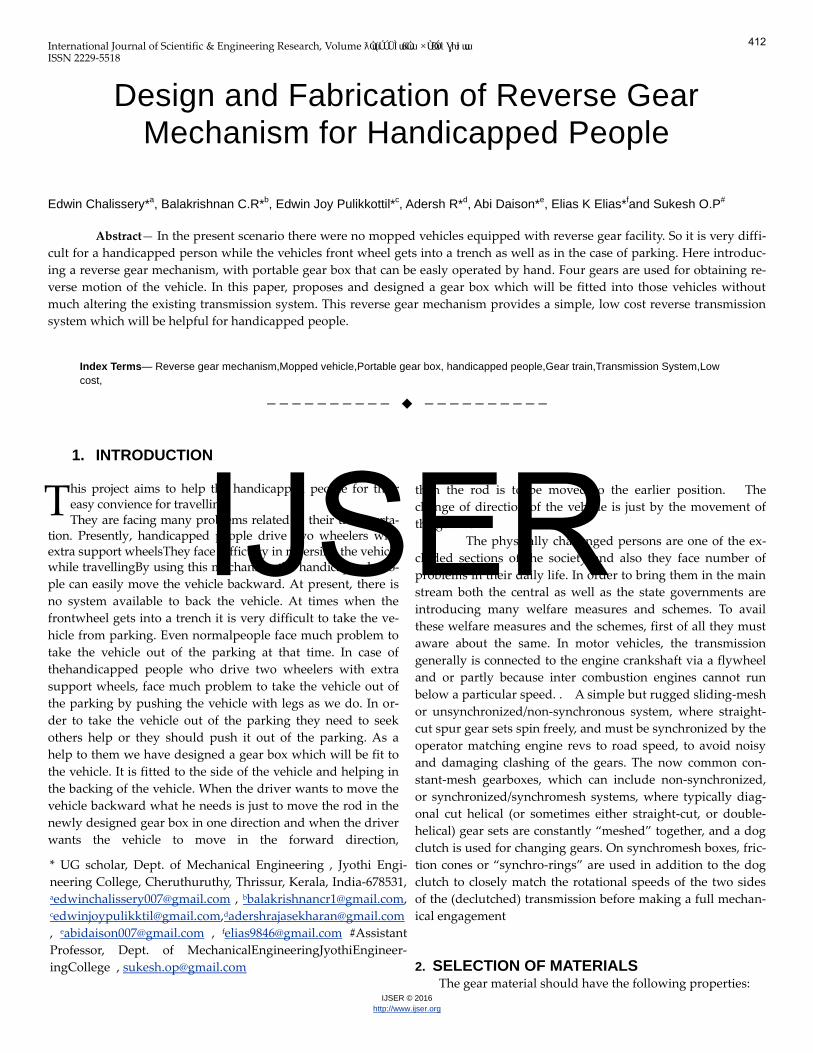
4. SCHEMATIC DIAGRAM FOR REVERSE GEAR
MECHANISM
Fig. 1 Schematic Diagram of reverse gear mechanism
In the manufacture of mechanical parts, knowledge of
material properties, cost, design concepts and their interac-tions is required. The large number of available materials, to-gether with the complex relationships between the various selection parameters, often makes the selection process a diffi-cult task. When selecting materials, a large number of factors must be taken into account. These factors are mechanical properties, physical and electrical properties, corrosion re-sistance, environmental friendliness and economy. In mechan-ical design, however, mechanical properties are the most im-portant. The most important mechanical material properties usually encountered in material selection process are fatigue strength, tensile strength, yield point, hardness, stiffness, toughness, creep resistance and density. After analyzing the following concepts we have choosen material for the gear as 40Ni 2Crl Mo Mo 28 . It is the one of the suitable that can be used for the production of the gear. It is very much cheaper and has a good manufacturability.[3]
5. WORKING OF REVERSE GEAR MECHANISM
A geartrain is a mechanical system formed by mount-
ing gears on a frame so that the teeth of the gears engage.
Gear teeth are designed to ensure the pitch circles of engaging
gears roll on each other without slipping, providing a smooth
transmission of rotation from one gear to the next.
The transmission of rotation between contacting toothed
wheels can be traced back to the Antikythera mechanism of
Greece and thesouth-pointing chariot of China. Illustrations by
the Renaissance scientist Georgius Agricola show gear trains
with cylindrical teeth. The implementation of the involute
tooth yielded a standard gear design that provides a constant
speed ratio.
413
IJSER
International Journal of Scientific & Engineering Research Volume ƛȮɯ(ÚÚÜÌɯƘȮɯ ×ÙÐÓɪƖƔƕƚɯɯ ISSN 2229-5518
IJSER © 2016http://www.ijser.org
Fig. 2 Assembly of Reverse Gear Mechanism
Gear teeth are designed so that the number of teeth on a gear
is proportional to the radius of its pitch circle, and so that the
pitch circles of meshing gears roll on each other without slip-
ping. The speed ratio for a pair of meshing gears can be com-
puted from ratio of the radii of the pitch circles and the ratio of
the number of teeth on each gear.
If the output gear of a gear train rotates more slowly
than the input gear, then the gear train is called
a speedreducer. In this case, because the output gear must
have more teeth than the input gear, the speed reducer ampli-
fies the input torque
6. BASIC LAW USED
Here we law of gearing as the most important law
used in our project
Where input gear A with radius rA and angular velocity
ωA meshes with output gear B with radius r and angular ve-
locity ωB. Therefore,
Where NA is the number of teeth on the input gear and NB is
the number of teeth on the output gear.[5]
The mechanical advantage of a pair of meshing gears for
which the input gear has NA teeth and the output gear
has NB teeth is given by
This shows that if the output gear GB has more teeth than the
input gear GA, then the gear train amplifies the input torque.
And, if the output gear has fewer teeth than the input gear,
then the gear train reduces the input torque. [4]
7. COMPONENTS
For the reverse gear mechanism we use different
components . Following essential components are described
below.
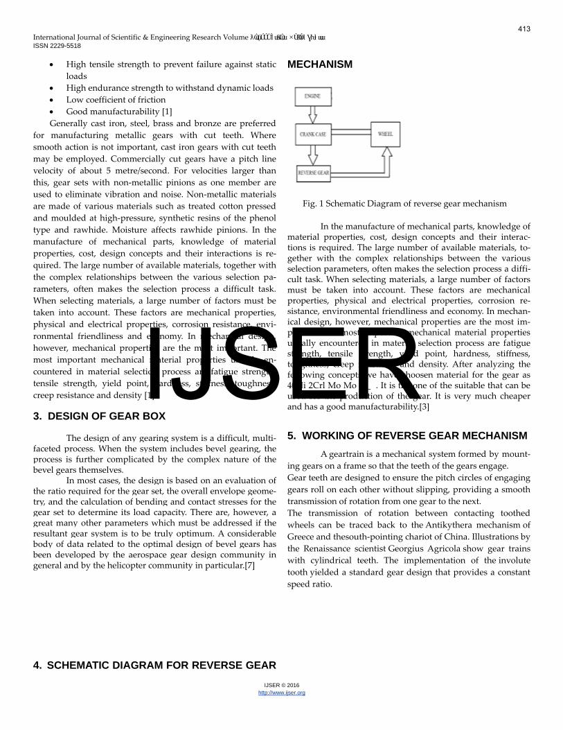
7.1 Spur gear: A gear is a rotating machine part having
cut teethes, which mesh with another toothed part to
transmit torque planet gear.
Fig. 3 Spur gear
7.2 Ball bearing ; A ball bearing is a type of balling ele-
ment bearing that uses balls to maintain the separation
between the bearing races
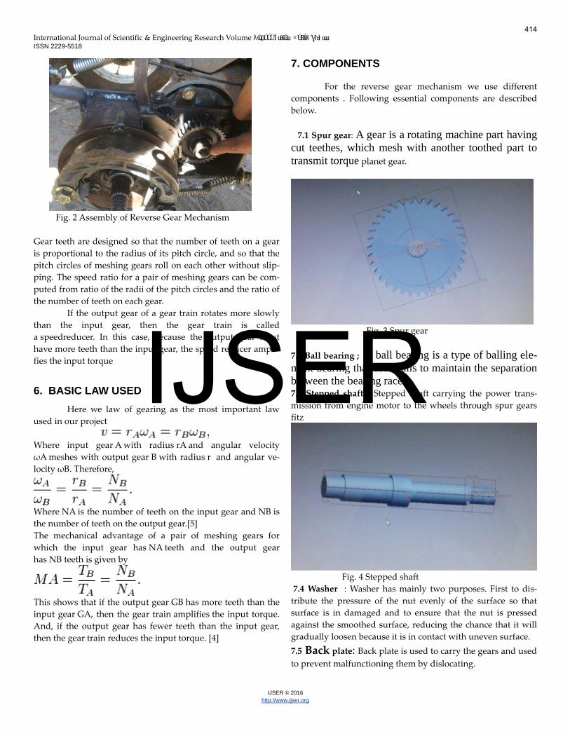
7.3 Stepped shaft : Stepped shaft carrying the power trans-
mission from engine motor to the wheels through spur gears
fitz
Fig. 4 Stepped shaft
7.4 Washer : Washer has mainly two purposes. First to dis-
tribute the pressure of the nut evenly of the surface so that
surface is in damaged and to ensure that the nut is pressed
against the smoothed surface, reducing the chance that it will
gradually loosen because it is in contact with uneven surface.
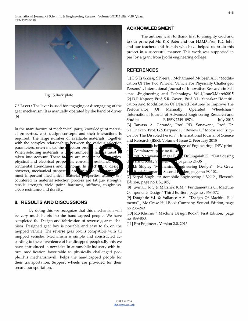
7.5 Back plate: Back plate is used to carry the gears and used
to prevent malfunctioning them by dislocating.
414
IJSER
International Journal of Scientific & Engineering Research Volume ƛȮɯ(ÚÚÜÌɯƘȮɯ ×ÙÐÓɪƖƔƕƚɯɯ ISSN 2229-5518
IJSER © 2016http://www.ijser.org
Fig . 5 Back plate
7.6 Lever : The lever is used for engaging or disengaging of the
gear mechanism. It is manually operated by the hand of driver
[6]
In the manufacture of mechanical parts, knowledge of materi-al properties, cost, design concepts and their interactions is required. The large number of available materials, together with the complex relationships between the various selection parameters, often makes the selection process a difficult task. When selecting materials, a large number of factors must be taken into account. These factors are mechanical properties, physical and electrical properties, corrosion resistance, envi-ronmental friendliness and economy. In mechanical design, however, mechanical properties are the most important. The most important mechanical material properties usually en-countered in material selection process are fatigue strength, tensile strength, yield point, hardness, stiffness, toughness, creep resistance and density.
8. RESULTS AND DISCUSSIONS
By doing this we recognize that this mechanism will
be very much helpful to the handicapped people. We have
completed the Design and fabrication of reverse gear mecha-
nism. Designed gear box is portable and easy to fix on the
mopped vehicle. The reverse gear box is compatible with all
mopped vehicles. Mechanism is simple and constructed ac-
cording to the convenience of handicapped peoples.By this we
have introduced a new idea in automobile industry with fu-
ture modification favourable to physically challenged peo-
ple.This mechanismwill helps the handicapped people for
their transportation. Support wheels are provided for their
secure transportation.
ACKNOWLEDGMENT
The authors wish to thank first to almighty God and
to our principal Mr. K.K Babu and our H.O.D Prof. K.C John
and our teachers and friends who have helped us to do this
project in a successful manner. This work was supported in
part by a grant from Jyothi engineering college.
REFERENCES
[1] E.S.Esakkiraj, S.Neeraj , Mohammed Mubeen Ali , “Modifi-
cation Of The Two Wheeler Vehicle For Physically Challenged
Persons” , International Journal of Innovative Research in Sci-
ence ,Engineering and Technology, Vol.4,Issue3,March2015
[2] D.P. Kapoor, Prof. S.R. Zaveri, Prof. Y.L. Yenarkar “Identifi-
cation And Modification Of Desired Features To Improve The
Performance Of Manually Operated Wheelchair”
,International Journal of Advanced Engineering Research and
Studies E-ISSN2249–8974, July-2013
[3] Tatyaso A. Garande, Prof. P.D. Sonawane, Prof. Dr.
S.T.Chavan, Prof. G.S.Barpande , “Review Of Motorized Tricy-
cle For The Disabled Person” , International Journal of Science
and Research (IJSR), Volume 4 Issue 2, February 2015
[4] Design data book, PSG College of Engineering, DPV print-
ers, Coimbatore ,page no 8.1-8.30
[5] Prof. Narayana Iyengar B.R & Dr.Lingaiah K “Data desing
data hand book, Vol 1 & Vol 2 page no 24-36
[6] J.E Shigley “Mechanical Engineering Design” , Mc Graw
Hill Book Company , Second Edition, page no 98-102.
[7] Kirpal Singh “Automobile Engineering “ Vol 2 , Eleventh
Edition, page no 1,36,185,
[8] Juvinall R.C & Marshek K.M “ Fundamentals Of Machine
Components Design” Third Edition, page no , 368-372.
[9] Doughtie V.L & Vallance A.V “Design Of Machine Ele-
ments” , Mc Graw Hill Book Company, Second Edition, page
no 235-249
[10] R.S Khurmi ” Machine Design Book”, First Edition, page
no 839-850.
[11] Pro Engineer , Version 2.0, 2015
415
IJSER