design and fabrication of soya seed fabrication machine
TRANSCRIPT

Design and Fabrication of Soya Seed Harvesting Machine
List of figure
Fig. No description Page No.
Fig. 1.1 Soya bean 3
Fig. 1.2 Hand threshing
Fig. 1.3 Treading of grain under the
feet of animals
Fig. 1.4 Winnowing
Fig. 3.1 Improve bean processing
Fig. 3.2 Classification of motor
Dept of MechEngg. KLE Dr MSSCET, Belagavi Page 1

Design and Fabrication of Soya Seed Harvesting Machine
List of Table
Table No. Description Page No.3.1 Morphological Chart for
design of product
Dept of MechEngg. KLE Dr MSSCET, Belagavi Page 2

Design and Fabrication of Soya Seed Harvesting Machine
Chapter 1
Introduction
The history of agriculture in India dates back to the Rig-Veda, written about 1100 BC. Today
India ranks second worldwide in farm output. Agriculture and allied structures like forestry
and fisheries accounted for 13.7% of the GDP (Gross Domestic Product) in 2013, about 50%
of the total workforce. The economic contribution of agriculture to India’s GDP is steadily
declining with the country’s broad-based economic growth. Still, agriculture is
demographically the broadest economic sector and plays a significant role in overall socio-
economic fabric of India.
As Per the 2010 FAO world agriculture statistics, India is the world's largest producer of
many fresh fruits and vegetables, milk, major spices, select fresh meats, select fibrous crops
such as jute, several staples such as millets and castor oil seed. India is the second largest
producer of wheat and rice, the world's major food staples.
Soyabean continues to be the preferred Kharif crop for farmers due to its high net returns.
The manual harvesting process is tedious and time consuming and moreover the labour costs
are high and also there is lack of laborers. The small scale farmers can’t afford harvesting
machines which are of high costs. Thus there is a need for cost effective low maintenance
soya seed harvesting machine.
Soyabean is grown as a rain fed crop in Kharif Season, asSoyabean is a high yielding crop
compared to other crops, Water Requirement of the crop is very less (110 mm), Time
duration is very less (3 months and 20 Days), Market rates of soyabean are economical.
Dept of MechEngg. KLE Dr MSSCET, Belagavi Page 3

Design and Fabrication of Soya Seed Harvesting Machine
1.1 Literature Survey
The soybean in North America, also called the soya bean (Glycine max) (fig.1.1) is, a
species of legume native to East Asia, widely grown for its edible bean which has numerous
uses. The plant is classed as an oilseed rather than a pulse by the UN Food and Agriculture
Organization (FAO).
Fat-free (defatted) soya bean meal is a significant and cheap source of protein for animal
feeds and many packaged meals; soya vegetable oils another product of processing the soya
bean crop. For example, soya bean products such as textured vegetable protein (TVP) are
ingredients in many meat and dairy analogues. Soya beans produce significantly more
protein per acre than most other uses of land.
Traditional non fermented food uses of soya beans include soy milk, from
which tofu and tofu skin are made. Fermented foods include soya sauce, fermented bean
paste, natto, and tempeh, among others. The oil is used in many industrial applications. The
main producers of soya are the United States (36%), Brazil (36%), Argentina (18%), China
(5%) and India (4%). The beans contain significant amounts of phytic acid, alpha-linolenic
acid, and isoflavones.
Fig. 1.1 Soya bean
Dept of MechEngg. KLE Dr MSSCET, Belagavi Page 4

Design and Fabrication of Soya Seed Harvesting Machine
During World War II, soyabeans became important in both North America and Europe
chiefly as substitutes for other protein foods and as a source of edible oil. During the war, the
soyabean was discovered as fertilizer by the United States Department of Agriculture. In the
1960–1 Dillon round of the General Agreement on Tariffs and Trade(GATT), the United
States secured tariff-free access for its soyabeans to the European market. In the 1960s, the
United States exported over 90% of the world's soyabeans. By 2005, the top soyabeans
exporters were Argentina (39% of world soyabean exports), United States (37%) and Brazil
(16%), while top importers were China (41% of world soyabean imports), European Union
(22%), Japan (6%) and Mexico (6%).
1.1.1 Threshing
The prime objective of the threshing process is to detach the sound or undamaged
grainkernels from the plants. In some crops, it also involves the removal of kernels from the
protective cover, called husk or pod. It is achieved by striking, treading, squeezing, tearing,
and rubbing actions or by combinations of these methods. Traditionally, threshing is
performed by treading the grain under the hooves of animals, striking the grains with sticks,
beating them over a log of wood or bamboo grating, or over a ladder, or using a stationary
power thresher of specific design for each crop, or between the rasp-bar and concave of a
combine. The machine used for the purpose of grain detachment and separation is called a
thresher and was introduced in India about 1960.
Timely preparation of seedbed and sowing of seasonal crops immediately after harvest are
the prime desire of all the farmers. To meet these requirements, threshing either needs to be
delayed or the farmers are required to use a stationary thresher. Delayed threshing will cause
not only spoilage of grain, but will also increase the breakage percentage during milling.
Hence, the use of stationary thresher, a faster method of grain detachment and separation for
cereal and pulse crops has become very common among all groups of farmers. Stationary
threshers are conventionally used when the fields are small and conditions are not favorable
for combine operation. For speedy and effective threshing, pedal- and power-operated
threshers are used, respectively, by the small to marginal- and medium-class farmers. With
Dept of MechEngg. KLE Dr MSSCET, Belagavi Page 5

Design and Fabrication of Soya Seed Harvesting Machine
the use of these threshers, threshing of most crops and separation of grains and seeds from un
threshed debris has become mechanized in all developed and underdeveloped countries.
1.1.1.2 Traditional Threshing
Conventionally, harvested paddy and wheat crops are either dried in the field or on a
cemented floor for 3–5 days to bring down the moisture content from 27–40% to 15–20%
when threshing operations are carried out. Threshing of immatured or moist grain would
result not only in more breakage, but would also require higher impact force for grain
detachment, and cleaning and grain separation from leftovers (broken stalks and chaffs)
would become difficult, requiring more impact power. An average laborer can thresh 15–22
kg/h of grain by hand-beating (Fig 1.2), or 110–140 kg/h by treading the grain under the feet
of animals (Fig 1.3).
Fig 1.2 Hand Threshing
Fig 1.3 Treading of Grain under the Feet of Animals
Dept of MechEngg. KLE Dr MSSCET, Belagavi Page 6
Design and Fabrication of Soya Seed Harvesting Machine
In either method, sound grains are separated using a winnower operated by human or by a
power unit or dropping the mix against the medium to high natural wind. Thus, the
separation of sound grain and manual bagging require additional labor, making the entire
process tedious, time-consuming, and labor-intensive. It thus brings down the overall
threshing ability of a laborer to 12–18 kg/h in manual threshing and 80–120 kg/h by treading
the grain under the feet of animals. Therefore, traditional methods of threshing are
considered a slow process of grain detachment. Small and marginal farmers of South and
Southeast Asia knowingly follow these methods because of capital constraint and limited
production of cereal and pulse crops.
1.1.1.2 Pedal Threshing
Threshers of different designs and capacities are being manufactured by various
manufacturers in all the countries. They are either throw-in or hold-on type. The Japanese-
type rotary drum thresher, a hold-on type is the first of its kind developed in Japan for
threshing paddy crops. Such a thresher is common with small farmers of paddy-growing
countries. It is cheap, compact, and simple in construction. It consists of a threshing cylinder
(420mm in diameter and 400–700 mm long) with wire loops, driving mechanism, and
supporting frame. The rotary motion to the drum is given by a crank mechanism from a
treadle and two cast iron gears (80 and 20 teeth) with 1:4-speed gain to achieve a cylinder
speed between 300 and 375 rpm (6–7.8 m/s). The threshing drum mounted with a large
number of wireloops at its periphery and at regular intervals shatters grain by impact and
combing actions. Most grains from paddy are detached when the tiller ends of crop bundle is
held over the rotating cylinder along the motion direction. One man can thresh about 1.5–2.0
q/day but additional labor is required to separate grain from chaff and other debris. To
increase the capacity, farmers engage four to six laborers for threshing over a 1.5- to 2.4- m–
long threshing cylinder made locally and operated by a 3.75-kW diesel engine through a flat
belt. An additional two- to four men are engaged for the supply of crop bundles near the
thresher and grain separation. This method in contrast with manual threshing, therefore,
saves time and energy, and at the same time reduces human drudgery to a large extent.
Dept of MechEngg. KLE Dr MSSCET, Belagavi Page 7

Design and Fabrication of Soya Seed Harvesting Machine
1.1.1.3 Power Threshing
The prime functions of threshing units are to detach sound grain kernels and kernels from
husk or pod; separate them from broken stalks, leftovers, and chaffs; convey and deliver the
sound and unbroken grains or seeds, free from foreign materials, to a delivery outlet and bag
the grains. Because operations such as detachment, separation, conveying, and elevating of
grains or kernels are done simultaneously and in sequence, a prime-mover with a capacity in
the 3.5- to 30.0-kWrange is necessary, depending on the crop parameters, type, and size of
threshing cylinder and feed rate.
Power-driven threshers are very similar to the threshing units used in a combine harvester.
The large-sized threshers are mostly throw-in type and are provided with a belt conveyor as
self-feeder to the threshing cylinder on which the workmen, uniformly and evenly, place the
crop material. Throw-in types are conventionally axial-flow threshers that not only detach
cereal and pulse grain or seeds by impact and combing actions, but also break the leftover
straw during their flow axially against the louvers provided on the inner surface of the
cylinder cover. Effective removal of the grain from tillers and seed separation from husk
occur in an axial-flow thresher, rather than in low-capacity hold-on type threshers in which
crop panicles are held manually for some time against the rotating threshing drum. The
leftovers in the form of bhusa(broken straw and chaffs) obtained from axial-flow thresher are
used as cattle feed or left in the field as fertilizer, whereas the whole crop straw obtained
from the
hold-on threshers is used as the raw material for industries manufacturing straw boards,
Khaskhas, ropes, and are also used to thatch roofs, and as animal feed.
Detachment of seeds and breaking of pods are primarily achieved by impact action, wherein
squeezing, rubbing, combing, and tearing actions are also associated between the threshing
elements and concave grating. Unlike manual threshing, the impact actions inthreshers are
simulated by rotating the cylinder(s) having threshing elements of different designs at their
periphery and along the drum length. When such cylinders are rotated at high speed (7.5–
30.0 m/s), most grains or pods from the straw, which is moving relatively slowly, are
Dept of MechEngg. KLE Dr MSSCET, Belagavi Page 8

Design and Fabrication of Soya Seed Harvesting Machine
shattered by the repeated impacts. The remaining grains are threshed by the combing,
rubbing, squeezing, and tearing actions as the crops accelerate and pass through the narrow
passages between the cylinder element tip and the concave, as well as with the louvers.
During the separation process, it is assumed that, theoretically, a sheet of crops giving
cushioning effect to the grains rolls over the cylinder when impact shatters most grains.
Increased crop thickness or high feed rate will, therefore, relatively reduce grain damage and
separation from panicle, and vice versa. Proper selection and adjustment of design and
system parameters (discussed later) for effective threshing will primarily depend on the
moisture content and feed rate of the selected crop.
1.1.2 Threshing Cylinder and Concave
The threshing cylinder and the matching concave are the heart of a combine harvester and
stationary power thresher. Most commonly used threshing cylinders are provided with wire-
loop, spiked-tooth, flat-bar, rasp-bar, or angle iron bar as elements called the threshing
elements of the cylinder. Hammer mill- and serrated flywheel-types are also used in axial-
flow threshers. The constructional details as well as the operating principles of each type of
threshing cylinder are discussed in the following.
1.1.2.1 Wire-Loop and Spike-Toothed Cylinders
The elements, such as wire-loops and spike-tooth or studs, are placed at regular intervals
along the drum length, but staggered in subsequent rows around its periphery to provide
impact, rubbing, and combined actions to the crop during its flow through the restricted
passages. The concave grating of steel rods and flats covers one-third to five-twelfth of drum
periphery. It is pivoted at the rear, whereas the front is made adjustable vertically to control
clearance between them. A typical 3.75-kW thresher may have 650 _ 480- mm–diameter
threshing cylinder with 40–50 beaters (6-mm rod for wire-loop or 18- to 20-mm side
square/diameter bar as a spike or stud), designed to be operated at 20.5 and 24.0 m/s for
paddy and wheat crops, respectively. The total number of rows of wire-loop (for paddy) or
spike-tooth (for wheat) on the drum periphery depends on the crop, moisture content, feed
Dept of MechEngg. KLE Dr MSSCET, Belagavi Page 9

Design and Fabrication of Soya Seed Harvesting Machine
rate, and peripheral velocity. Rubber or plastic-lined loops, spike-tooth, and corrugated
spikes, or studs as beaters are also used for difficult threshing conditions.
1.1.2.2 Rasp-Bar Cylinders
The rasp-bar-type threshing cylinders are provided with left and right rasps, or a raised
configuration alternately along its length and at regular intervals over the drum periphery to
balance the side thrust-with numbers varying between six and ten (even number). Grain
separation is obtained between the corrugated bars and concave grate. Sometimes, a flat-bar
grate, in place of corrugated grates, is used as the concave. Rubbing and tearing actions are
primarily responsible for grain detachment and breakage of straw. Apart from groundnut,
rasp-bar cylinders are adopted for a wide variety of crops and threshing conditions because
the actions of rasps on crops are mild. It is recommended for pulse crop threshing in
stationary threshers and cereal crop threshing at high moisture in a straight-through combine
harvester.
1.1.2.3 Flat-Bar Cylinders
The construction of a threshing cylinder, with or without corrugations in flat-bars, is similar
to that of a spike-tooth cylinder of a stationary thresher, but is made more rigid and strong for
threshing wheat crops. Besides the use of standard concave grating of steel rods and flat-bars,
as in other threshers, the louvers are placed on the inner surface of the cover for axial-flow of
crop materials, effective straw breakage, and grain separation. The grain detachment and
straw breakage are primarily due to impact, and successive grain separation is due to rubbing
and tearing actions against the concave grate and louvers.
1.1.2.4 Angle-Iron-Bar Cylinders
A total of six to ten angle-iron bars in place of rasp-bars are mounted rigidly and regularly
over the drum periphery to form the cylinder, and a concave grating of steel rods and flats is
provided to separate grains from panicles, primarily by impact. Subsequent grain detachment
Dept of MechEngg. KLE Dr MSSCET, Belagavi Page 10

Design and Fabrication of Soya Seed Harvesting Machine
during its flow through a restricted passage occurs by rubbing and tearing actions in axial-
flow threshers. This type of threshing cylinder is easily adaptable to a wide variety of crop
and threshing conditions, and has less tendency to break up the straw. The angle-bar
cylinders, therefore, are recommended for threshing millets, barley, and other small seeds,
and also in straight-through combines.
1.1.2.5 Hammer-Mill- or Beater-Type Cylinders
Threshers using this type of cylinder are called drummy, hammer-mill-type, or beater type
threshers. They are normally recommended for threshing crops such as wheat, barley,
sorghum, and pearl millet. The threshing drum of such threshers consists of beaters mounted
on a shaft that rotates inside a concave closed casing that is provided with a cleaning system.
Additionally, angle-iron ribs, parallel to the drum axis, are provided at the upper casing for
effective grain separation. A typical 5.6-kW drummy thresher may have 650-mm–diameter
and 460-mm–wide threshing cylinder with 10–16 beaters designed to rotate at a peripheral
speed of 16–20 m/s. The cylinder is rotated counterclockwise when viewed from the feeding
end. Grains are primarily detached by impact action of the beaters, and subsequent separation
is obtained by rubbing and tearing actions against the concave grate and angle-iron ribs. The
cleaning sieves and an aspirator–blower are provided on a separate shaft. The oscillating
sieves placed below the concave receive the threshed material (grains, chaff, and broken
straw). The lighter materials during their fall are sucked by the aspirator–blower and thrown
at a greater distance. The upper sieve receives thick straw (mostly nodes for wheat) and
overflows, while the clean grains are received by the bottom sieve. The lowermost sieve
separates broken and fine materials from clean, sound grains of wheat. This type of thresher
requires more power and can provide fine bruised wheat straw (bhusa).
1.1.2.6 Serrated Flywheel- or Chaff-Cutter-Type Cylinder
Threshers provided with this type of cylinder are also called serrated flywheel-type, chaff
cutter-type, syndicator- or toka-type threshers that are primarily used to thresh wheat crop
that may become wet owing to the postharvest monsoon. Unlike beaters in a hammer-mill
type thresher, the syndicator-type thresher is provided with a flywheel having serrations on
Dept of MechEngg. KLE Dr MSSCET, Belagavi Page 11

Design and Fabrication of Soya Seed Harvesting Machine
its periphery and sides, closed casing, and concave, and ensilage cutter-type chopping blades
fitted at regular intervals on the flywheel rim. Through the feeding chute, the whole crop is
fed axially into the threshing cylinder. The grain separation is obtained by rubbing actions
between the serrated surfaces of the flywheel and stationary concave grate. Additional
beaters impart impact. The material makes three-quarter turns axially during which threshing
occurs before encountering the chopping knife which cuts the straw into small pieces. A
typical 7.5-kW toka thresher may have 900-580 mm sized threshing drum with closed
concave and two to four chopping knives. They are designed to operate at an optimum
peripheral velocity of 18.2–20.7 m/s. Such threshers are popular among the farmers because
they can thresh moist crop and consume less power, provide chopped straw as animal feed,
and deliver clean grain separately.
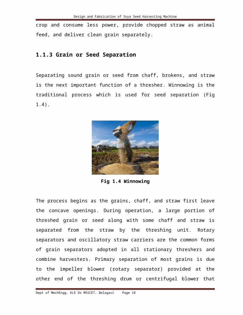
1.1.3 Grain or Seed Separation
Separating sound grain or seed from chaff, brokens, and straw is the next important function
of a thresher. Winnowing is the traditional process which is used for seed separation (Fig
1.4).
Fig 1.4 Winnowing
The process begins as the grains, chaff, and straw first leave the concave openings. During
operation, a large portion of threshed grain or seed along with some chaff and straw is
separated from the straw by the threshing unit. Rotary separators and oscillatory straw
carriers are the common forms of grain separators adopted in all stationary threshers and
combine harvesters. Primary separation of most grains is due to the impeller blower (rotary
Dept of MechEngg. KLE Dr MSSCET, Belagavi Page 12

Design and Fabrication of Soya Seed Harvesting Machine
separator) provided at the other end of the threshing drum or centrifugal blower that blows
off the light materials through the chaff outlet. Subsequent separation of the remaining free
seeds and unthreshed seeds occur as they are agitated and moved over the oscillating straw
carrier. The oscillating straw rack, a one-piece straw carrier, and multiple sections (pieces) of
straw walker are commonly used for the separation process and have been accepted widely
for grain harvesting and threshing machines.
1.1.3.1 Straw Walkers
A multiple piece, oscillating straw walker, having three or four narrow sections placed side
by side in the machine, is commonly used in recent threshers for grain separation. Multiple
throw crankshafts, one at the front and the other at the rear are attached to the individual
section. The crank throw of each section is spaced at equiangular spacing (π/2 or 2π/3
radians) around the circle of motion. The recommended crank speed of the oscillating straw
racks or walkers is between 215 and 260 rpm. Either a too high or too low speed of the crank
will increase seed losses as spilled grain. During its motion, the straw rack accelerates
the straw in rearward and upward directions in one and onehalfcycle of rotation whereas in
the return stroke, the rack tends to leave the straw in midair for a moment. As a result, the
grains heavier than straw fall onto the section near to the discharge end. In the next stroke of
the crank, the grains move one step toward the rear. This process continues and separates the
grain from straw as they walk over the straw rack or walker.
Dept of MechEngg. KLE Dr MSSCET, Belagavi Page 13

Design and Fabrication of Soya Seed Harvesting Machine
Chapter 2
Objective
1) Surveying and identification of local grain farmers and grain growing associations to
learn more about current harvesting practices, grains produced, and emerging
difficulties in local grain harvesting.
2) Study of harvesting equipment’s being used by the farmers.
3) Conduct archival research and review patents on small-scale combine harvesters,
binders, and threshers from the past.
4) Design and fabrication of soya seed harvesting machine for small scale farmers at
affordable rate.
Dept of MechEngg. KLE Dr MSSCET, Belagavi Page 14

Design and Fabrication of Soya Seed Harvesting Machine
Chapter 3
Design Methodology
3.1 Conceptual Design through Morphological Chart
Table No. 3.1 Morphological Chart for design of product
Parameters Solutions
Profile Cylindrical Rectangular
bar
Flat
Threshing element
of cylinder
Mild steel
spikes
Canvas spikes Wooden spikes
Principle of
threshing
Rubbing and
beating action
Beating action Rubbing Cutting, Rubbing
and beating action
Concave
construction
material
Mild steel Cast iron wood
Power source Electric motor Diesel engine Tractor
Feed rate 100kg/hr 50kg/hr
The highlighted solutions are selected.
Dept of MechEngg. KLE Dr MSSCET, Belagavi Page 15

Design and Fabrication of Soya Seed Harvesting Machine
3.2 Factors used for bean processing
Dept of MechEngg. KLE Dr MSSCET, Belagavi Page 16

Design and Fabrication of Soya Seed Harvesting Machine
Fig. 3.1 Improve bean processing
3.3 Fundamentals of motor
Dept of MechEngg. KLE Dr MSSCET, Belagavi Page 17
Design and Fabrication of Soya Seed Harvesting Machine
Before we can examine the function of a drive, we must understand the basic operation of the
motor. It is used to convert the electrical energy, supplied by the controller, to mechanical
energy to move the load. There are really two types of motors, AC and DC. The basic
principles are alike for both. Magnetism is the basis for all electric motor operation. It
produces the force required to run the motor. There are two types of magnets the permanent
magnet and the electro magnet. Electro magnets have the advantage over permanent magnet
in that the magnetic field can be made stronger. Also the polarity of the electro magnet can
easily be reversed. The construction of an electro magnet is simple.
When a current passes through a coil of wire, a magnetic field is produced. This magnetic
field can be made stronger by winding the coil of wire on an iron core. One end of the electro
magnet is a north pole and the other end is a south pole. The poles can be reversed by
reversing the direction of the current in the coil of wire. Likewise, if you pass a coil of wire
through a magnetic field, a voltage will be induced into the coil and, if the coil is in a closed
circuit, a current will flow.
3.4 Classification of motor
Dept of MechEngg. KLE Dr MSSCET, Belagavi Page 18

Design and Fabrication of Soya Seed Harvesting Machine
Fig. 3.2 Classification of motor
Dept of MechEngg. KLE Dr MSSCET, Belagavi Page 19

Design and Fabrication of Soya Seed Harvesting Machine
Chapter 4
Design Calculation
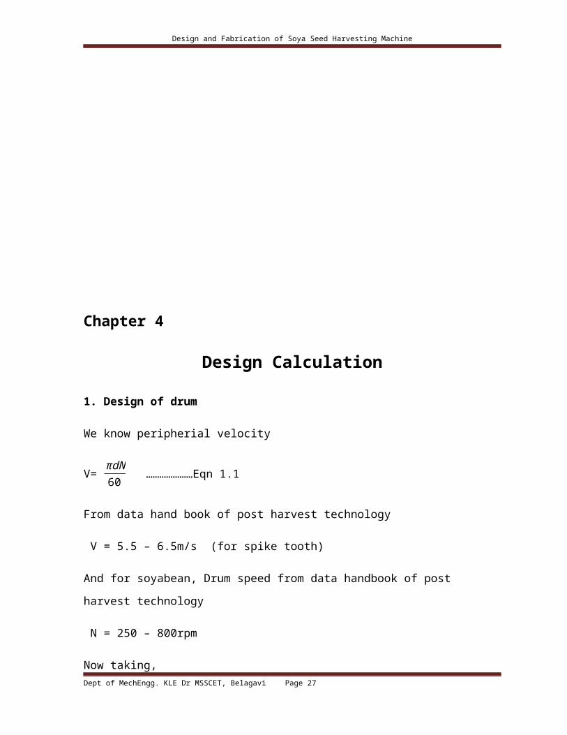
1. Design of drum
We know peripherial velocity
V= πdN60 …………………Eqn 1.1
From data hand book of post harvest technology
V = 5.5 – 6.5m/s (for spike tooth)
And for soyabean, Drum speed from data handbook of post harvest technology
N = 250 – 800rpm
Now taking,
V = 5.5m/s And
N = 750rpm
We have,
V= πdN60
5.5 = π × d× 750
60
d =60× 5.5750 × π
d = 0.140 m
d = 140 mm
Therefore, taking the available drum size d = 150 mm
Dept of MechEngg. KLE Dr MSSCET, Belagavi Page 20

Design and Fabrication of Soya Seed Harvesting Machine
2. Tangential force required to crush soya husk
Let, A = crushing area of drum
D = drum diameter
F c= crushing strength for soyabean husk(0.4 kg/cm2)
Therefore, tangential force
F t= F c× A ……….………..Eqn 2.1
Now,A = l × h
A = 150 × 25 = 3750mm2
F c= 0.4 × 9.81
10 ×10 = 0.03924 N/mm2
F c= 0.03924 N/mm2
Therefore,
F t=¿ 3750 × 0.03924 N
F t=¿147.15N
Dept of MechEngg. KLE Dr MSSCET, Belagavi Page 21

Design and Fabrication of Soya Seed Harvesting Machine
3. Torque required to produce F t
We know,
T = F t× r …………………….Eqn 3.1
T = 147.15 × 106.5
T = 15671.475 N-mm
T = 15.671475 N-m
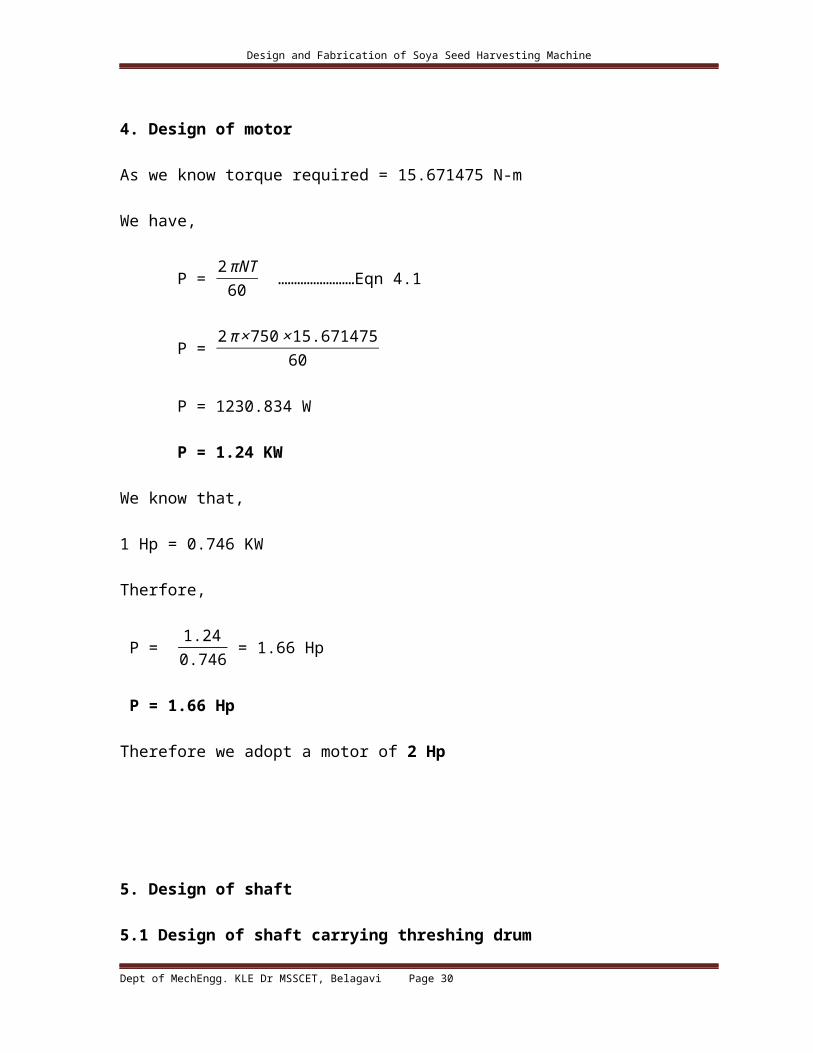
4. Design of motor
As we know torque required = 15.671475 N-m
We have,
P = 2πNT
60 ……………………Eqn 4.1
P = 2π ×750 ×15.671475
60
P = 1230.834 W
P = 1.24 KW
We know that,
1 Hp = 0.746 KW
Therfore,
P = 1.240.746 = 1.66 Hp
P = 1.66 Hp
Therefore we adopt a motor of 2 Hp
Dept of MechEngg. KLE Dr MSSCET, Belagavi Page 22

Design and Fabrication of Soya Seed Harvesting Machine
5. Design of shaft
5.1 Design of shaft carrying threshing drum
The maximum shear stress in a circular shaft subjected to torsion
= ح16 ×Tπ ×d3 (solid shaft) …………………….Eqn 5.1
Taking shaft material as carbon steel C50
Syt= 380 Mpa
For shear Ssy = 3802
=190 Mpa
Taking a FOS = 4
190ح = 4 = 47.5 Mpa
We have,
= ح16 Tπ d3
47.5 = 16 ×15671.475
π d3
d = 3√ 16× 15671.475π × 47.5
d = 11.88 mm
Therefore, taking standard shaft of diameter = 30mm
5.2 design of shaft connected to the siever
Force require to reciprocate the sieve = 70 NDept of MechEngg. KLE Dr MSSCET, Belagavi Page 23

Design and Fabrication of Soya Seed Harvesting Machine
This is the tangential force acting on the shaft
We know
Torque
T = F t ×r
r = radius of the disc mounted on the shaft and connected eccentrically to the siever
r = 14 mm
therefore,
T = 70 × 14 T = 980 N – mm
We know from Eqn. 5.1 = ح
16 ×Tπ ×d3 (solid shaft)
Taking shaft material as carbon steel C50
Syt= 380 Mpa
For shear Ssy = 3802
=190 Mpa
Taking a FOS = 4
190ح = 4 = 47.5 Mpa
We have,
= ح16 Tπ d3
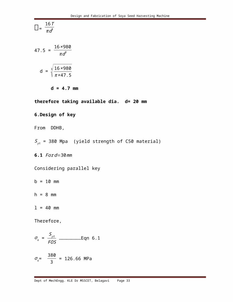
47.5 = 16 ×980
π d3
Dept of MechEngg. KLE Dr MSSCET, Belagavi Page 24

Design and Fabrication of Soya Seed Harvesting Machine
d = 3√ 16× 980π × 47.5
d = 4.7 mm
therefore taking available dia. d= 20 mm
6.Design of key
From DDHB,
Syt = 380 Mpa (yield strength of C50 material)
6.1 For d=30 mm
Considering parallel key
b = 10 mm
h = 8 mm
l = 40 mm
Therefore,
σ d = Syt
FOS ……………………Eqn 6.1
σ d= 3803 = 126.66 MPa
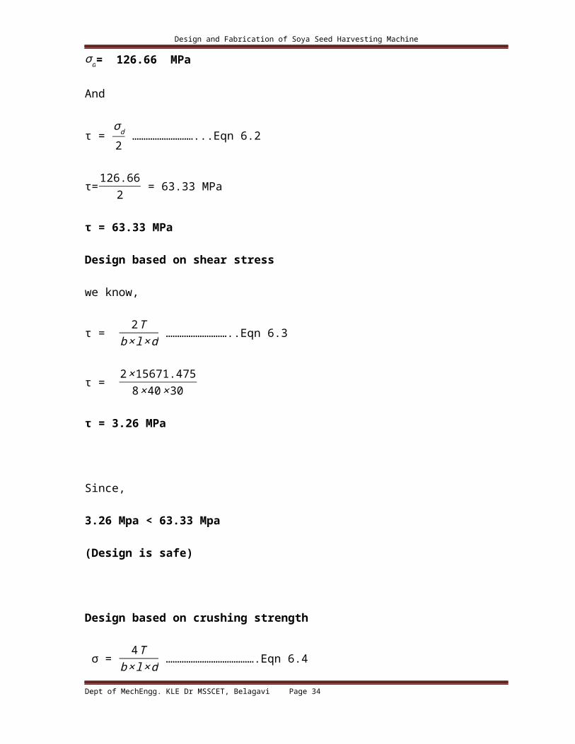
σ d= 126.66 MPa
And
τ = σd
2 ………………………...Eqn 6.2
τ=126.662 = 63.33 MPa
τ = 63.33 MPaDept of MechEngg. KLE Dr MSSCET, Belagavi Page 25

Design and Fabrication of Soya Seed Harvesting Machine
Design based on shear stress
we know,
τ = 2T
b ×l ×d ………………………..Eqn 6.3
τ = 2× 15671.475
8 × 40 ×30
τ = 3.26 MPaSince,3.26 Mpa < 63.33 Mpa (Design is safe)Design based on crushing strength σ = 4 T
b ×l ×d ………………………………….Eqn 6.4σ = 4 × 15671.475
8 ×40 × 30 = 6.52 MPaσ = 6.52 MPaSince,6.52 < 126 MPa (Design is safe)6.2 For d=20 mm
Considering parallel key
Dept of MechEngg. KLE Dr MSSCET, Belagavi Page 26
Design and Fabrication of Soya Seed Harvesting Machine
b = 6 mm
h = 6 mm
l = 36 mm
Therefore,
σ d = Syt
FOS ……………………Eqn 6.1
σ d= 3803 = 126.66 MPa
σ d= 126.66 MPa
And
τ = σd
2 ………………………...Eqn 6.2
τ=126.662 = 63.33 MPa
τ = 63.33 MPaDesign based on shear stress
we know,
τ = 2T
b ×l ×d ………………………..Eqn 6.3
τ = 2× 980
6 ×36 ×20
τ = 0.453 MPaSince,0.453 Mpa < 63.33 Mpa (Design is safe)Dept of MechEngg. KLE Dr MSSCET, Belagavi Page 27

Design and Fabrication of Soya Seed Harvesting Machine
Design based on crushing strength σ = 4 T
b ×l ×d ………………………………….Eqn 6.4σ = 4 × 980
6 ×36 ×20 = 0.907 MPaσ = 0.907 MPaSince, 0.907 < 126 MPa (Design is safe)7 Design of PulleyTaking std. pulley dia. = 75 mm for the motor shaftWe haveN1
N 2 =d1
d2 …………………………………Eqn.7.1
N1= 1440 rpm (std. 2 Hp motor)N 2 = 750 rpm ( from data handbook of post harvest technology)Therefore,Eqn. 7.1 becomes1440750 = d2
75
d2 = 144 mmDept of MechEngg. KLE Dr MSSCET, Belagavi Page 28

Design and Fabrication of Soya Seed Harvesting MachineTherefore,Available std. dia = 150 mm
d2=150 mm , N2=750 rpm d1=75 mm, N1=1440 rpm
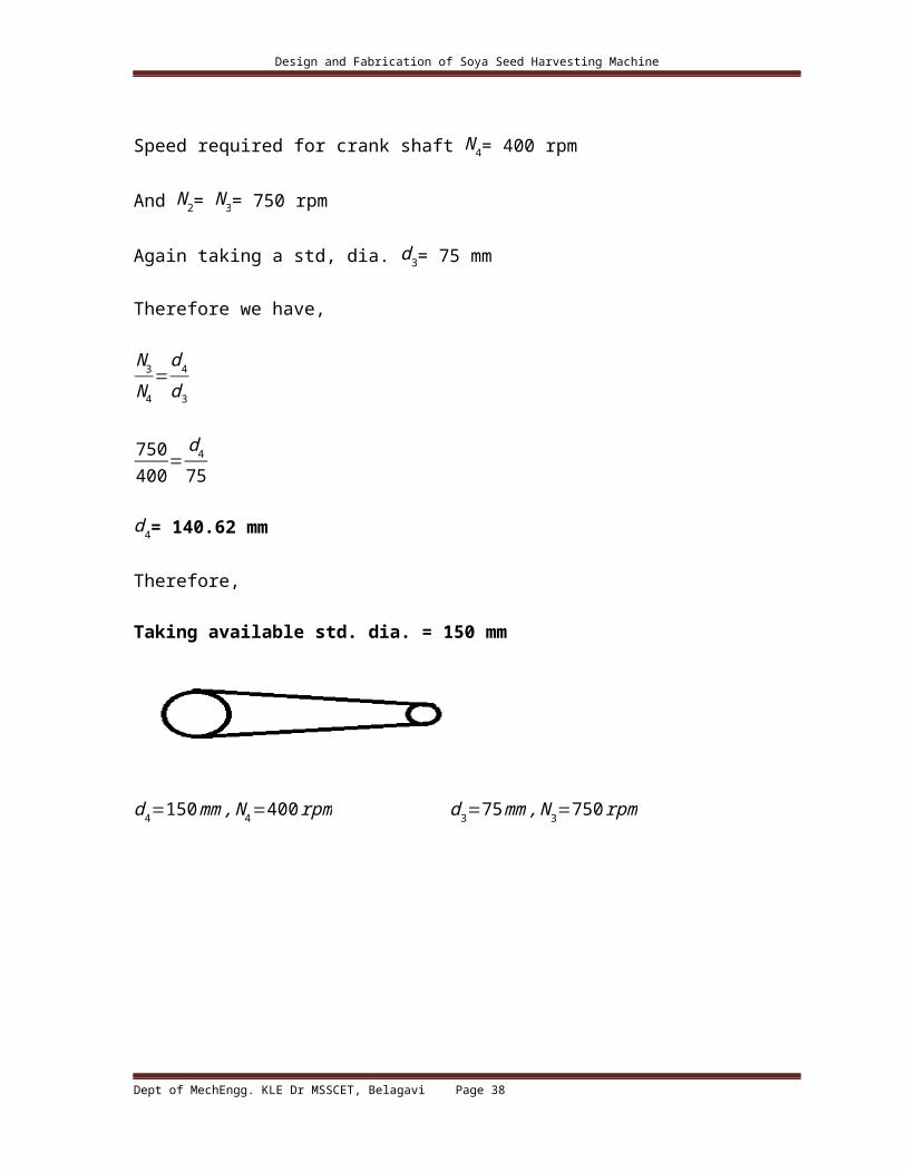
Speed required for crank shaft N 4= 400 rpm
And N 2= N3= 750 rpm
Again taking a std, dia. d3= 75 mm
Therefore we have,
N 3
N 4=
d4
d3
750400
=d4
75
d4= 140.62 mm
Therefore,
Taking available std. dia. = 150 mm
d4=150 mm, N 4=400 rpm d3=75 mm, N3=750 rpm
Dept of MechEngg. KLE Dr MSSCET, Belagavi Page 29
Design and Fabrication of Soya Seed Harvesting Machine
8. Design of V –belt
8.1 Selection of the cross section of the belt
The equivalent pitch diameter from Lingaiah DDHB
De = Fb Dp ………………….Eqn. 8.1
For N 1N 2 =1.92
From DDHB Table 22-25
Small Diameter factor
Fb = 1.13
And we have motor pulley dia.D p = 75 mm
De= 75 ×1.13
De=84.75mm.
From Lingaiah DDHB
For max value of
De = 125 mm
We select A- type cross-section belt.
For A-Type cross – section belt
From Lingaiah DDHB
Nominal top width W = 13 mm
Dept of MechEngg. KLE Dr MSSCET, Belagavi Page 30

Design and Fabrication of Soya Seed Harvesting Machine
Nominal thickness T = 8 mm
8.2 Angle of Lap
From lingaiah DDHB
θ1= π−(D 2−D1C ) ………………………Eqn. 8.2
Where
D2 & D1 are diameter of larger and smaller pulley respectively and C is the center distance
b/w the pulleys
θ1= π−( 150−75410 )
θ1= 2.958 radians
θ1= 169.5°And also,
θ2= π+( D 2−D 1C )
θ2=π+( 150−75410 )
θ2= 3.324 radians
θ2= 190.48°Dept of MechEngg. KLE Dr MSSCET, Belagavi Page 31

Design and Fabrication of Soya Seed Harvesting Machine
8.3 Tension in the belt
We know that,
Ratio of belt tensions is equal to
T1
T2 =
eμ θ
sin α2 ……………………………Eqn. 8.3
Taking standard groove angle α = 34°And μ = 0.3And θ = 2.95 radians We haveT1
T2=
e0.3 2.95
sin 342
T1
T2=19.74 ………………A
Also we know,
Pd= ¿ -T 2) × v ……………………………….Eqn. 8.4
And also,
Pd= K LP
Taking load factor K L= 1.1
Pd= 1.1 × 1230.834
Pd= 1353.91 watts
Also,
v = πdN60
Dept of MechEngg. KLE Dr MSSCET, Belagavi Page 32
Design and Fabrication of Soya Seed Harvesting Machine
Therefore,
v = π × 0.075× 144060
v = 5.65 m/s
Therefore,
Pd = ¿ -T 2) × 5.65
¿ -T 2) = 1353.91
5.65
¿ -T 2) = 239.63 ……………..B
Solving A & B we get
We get
T 1= 252.41 N
&
T 2 = 12.78 N
8.31 Check calculation
We know that,
Dept of MechEngg. KLE Dr MSSCET, Belagavi Page 33
Design and Fabrication of Soya Seed Harvesting Machine
Maximum tension in the belt T 1= S ×b× t ……………..Eqn. 8.5
Where S = tensile stress for the belt in N/mm2
We have
b = 13 mm
t = 8 mm
Therefore, Eqn. 7.5 becomes
S = 252.4113 × 8
S = 2.42 N/mm2
For belt material the tensile stress is 8-25 MPa
Therefore,
The design is safe.
8.4 Length of belt
From Lingaiah DDHB
Length of the belt
L =π2 × (d1+d2 )+2 C+
(d2−d1 )2
4 C ………………….Eqn. 8.6
L = π2
× (75+150 )+2× 410+(150−75 )2
4 ×410
L = 1176.85 mm
From Lingaiah DDHB
Dept of MechEngg. KLE Dr MSSCET, Belagavi Page 34

Design and Fabrication of Soya Seed Harvesting Machine
Table 21-29
Nominal pitch length = 1204 mm
Nominal inside length = 1168 mm
9 Design of Frame
Square cross section as shown below
Moment of inertia
I = (B H3−b h3 )12
………………………..Eqn. 9.1
Where B =32 mm, H = 32 mm, b = 26 mm, h = 26 mm.
Therefore Eqn. 9.1 becomes
I = (32× 323−26 ×263 )12
I = 49300 mm4
We know
Radius of gyration
Dept of MechEngg. KLE Dr MSSCET, Belagavi Page 35

Design and Fabrication of Soya Seed Harvesting Machine
K = √ IA
……………………………Eqn. 9.2
Where I = moment of inertia
And A = Area of cross section
A = BH−bh
A = 322−262
A = 348 mm2
Therefore,
I = √ 49300348
I = 11.90 mm
Assumed weight of the machine = 200 kg = 2000 N
No. of legs = 4
Weight on each leg = F4
W= 2000
4
W = 500 N
Also we know
Crippling load F cr=n × F
Where n = Factor of safety
Taking n = 3
F cr=3× 500
F cr=1500 N
Dept of MechEngg. KLE Dr MSSCET, Belagavi Page 36

Design and Fabrication of Soya Seed Harvesting Machine
From Rankine’s formula
F cr=σ × A
1+α L2
K2 ……………………………Eqn. 9.3
L = 532 mm
Taking α = 1
7500
F cr=σ × 348
1+ 17500
5322
11.902
1500= σ ×348
1+ 17500
5322
11.902
Solving the above equation
We get,
σ=5.45 MPa
Taking C 50 material
Yield strength Syt=380 MPa
Taking Fos = 3
Design stress
σ d = S yt
n
σ d = 3803
σ d = 126.66 MPa
5.45 MPa < 126.66 MPaDept of MechEngg. KLE Dr MSSCET, Belagavi Page 37
Design and Fabrication of Soya Seed Harvesting Machine
Therefore,
The design is safe
Chapter 5
Diagram
Rotary cutter
Dept of MechEngg. KLE Dr MSSCET, Belagavi Page 38

Design and Fabrication of Soya Seed Harvesting Machine
Rotary cutter assembly
Dept of MechEngg. KLE Dr MSSCET, Belagavi Page 39

Design and Fabrication of Soya Seed Harvesting Machine
Drum cover
Dept of MechEngg. KLE Dr MSSCET, Belagavi Page 40

Design and Fabrication of Soya Seed Harvesting Machine
BlowerDept of MechEngg. KLE Dr MSSCET, Belagavi Page 41

Design and Fabrication of Soya Seed Harvesting Machine
Frame
Dept of MechEngg. KLE Dr MSSCET, Belagavi Page 42

Design and Fabrication of Soya Seed Harvesting Machine
Seive
Pulley
2 – D Design
Dept of MechEngg. KLE Dr MSSCET, Belagavi Page 43

Design and Fabrication of Soya Seed Harvesting Machine
3 – D Design
Dept of MechEngg. KLE Dr MSSCET, Belagavi Page 44

Design and Fabrication of Soya Seed Harvesting Machine
Dept of MechEngg. KLE Dr MSSCET, Belagavi Page 45

Design and Fabrication of Soya Seed Harvesting Machine
Chapter 6
Applications
1. Harvesting of Soya Seed.
2. By changing the sieve size, this machine can be used to harvest other grains also.
Dept of MechEngg. KLE Dr MSSCET, Belagavi Page 46

Design and Fabrication of Soya Seed Harvesting Machine
Chapter 7
Advantages
1. Reduced harvesting time.
2. By using this machine the problem of labour crises can be reduced. Comparing with
manual harvesting only 18% of labours are required.
3. It increases overall productivity.
4. Efficient work is done by using this machine harvester.
5. Cost of harvesting is comparably less as manual harvesting.
6. Up to 90% of grains are unbroken(good quality grains).
Dept of MechEngg. KLE Dr MSSCET, Belagavi Page 47
Design and Fabrication of Soya Seed Harvesting Machine
Chapter 8
Disadvantages
1. This harvester requires electricity
Dept of MechEngg. KLE Dr MSSCET, Belagavi Page 48

Design and Fabrication of Soya Seed Harvesting Machine
Chapter 9
Conclusion
Dept of MechEngg. KLE Dr MSSCET, Belagavi Page 49

Design and Fabrication of Soya Seed Harvesting Machine
Chapter 10
References
[1] Amalendu Chakraverty, Hand book of Post-Harvest technology, Indian Institute of
Technology, Kharagpur. ISBN: 0-8247-0514-9.
[2] M. C. Siemens and D. E. Hulick, technical paper on “A new Grain Harvesting system for
single‐pass grain harvest”.
[3] K.N Singh, B singh- Journal of agricultural engineering research, July 1981.
[4] Adarsh J Jain , Shashank Karne, Srinivas Ratod , Vinay Thotad and Kiran , “Design and
Fabrication of Small Scale Sugarcane Harvesting Machine”, Vol. 2, No. 3, July 2013, ISSN
2278 – 0149.
[5] H.G. Patil, Machine Design Data Handbook, ISBN: 978-93-80578-96-5.
[6] Lingaiah K, Machine Design Data Handbook Vol. 1, ISBN: 4567142681.
[7] R.S. Khurmi and J.K. Gupta, A Textbook of Machine Design, ISBN: 8121925371.
[8] V.B. Bhandari, Design of Machine Elements, ISBN: 0070611416.
[9] R.K. Rajput, A Textbook of Manufacturing Technology: Manufacturing Processes, ISBN:
9788131802441.
[10] P.N. Rao, Manufacturing Technology, ISBN: 9789332901001.
Dept of MechEngg. KLE Dr MSSCET, Belagavi Page 50