design and implementation of a statcom based on a
TRANSCRIPT

energies
Article
Design and Implementation of a STATCOM Based ona Multilevel FHB Converter with Delta-ConnectedConfiguration for Unbalanced Load Compensation
Wei-Neng Chang 1,* and Ching-Huan Liao 2
1 Department of Electrical Engineering, Chang Gung University, 259 Wen-Hwa 1st Road, Kwei-Shan Dist.,333 Tao-Yuan City, Taiwan
2 National Chung-Shan Institute of Science and Technology, 486, 6th Neighborhood, Sec. Jia’an,Zhongzheng Road, Longtan Dist., 325 Tao-Yuan City, Taiwan; [email protected]
* Correspondence: [email protected]; Tel.: +886-3-211-8800
Received: 9 January 2017; Accepted: 28 June 2017; Published: 4 July 2017
Abstract: A delta-connected STATCOM with cascade multilevel full H-bridge (FHB) converter hasbeen applied for phase balancing and power factor correction of unbalanced load in a three-phase,three-wire power distribution system. In this paper, a feedforward compensation formula is presentedfor the STATCOM by using the symmetrical components method to compensate unbalanced load.Computer simulation is performed for preliminary verification. Accordingly, a hardware prototypeemploying a TMS320F2812 DSP-based system is built for final verification test. Experimental resultsshow that the proposed STATCOM is very effective for real-time unbalanced load compensation.
Keywords: FHB; hardware test; load compensation; STATCOM; symmetrical components method
1. Introduction
A large unbalanced capacity load, such as a single-phase electrical railway system, in a three-phase,three-wire electric power distribution system can absorb undesired negative-sequence currents andreactive power. The negative-sequence current and reactive power cause additional losses in the powerdistribution system and produce an unbalanced voltage drop on the distribution line, which should beimproved to ensure satisfactory power quality. Voltage fluctuations caused by large inductive loadssuch as electric arc furnace can induce light flicker. Therefore, unbalanced load compensation, includingphase balancing and power factor correction, is very important in electric power distribution systems.
Thyristor-controlled reactor with thyristor-switched capacitor (TCR-TSC) type static varcompensators (SVCs) with delta-connected configuration and individual-phase control are applied inpower distribution systems for real-time unbalanced load compensation and voltage regulation [1–6].In recent years, the static synchronous compensator (STATCOM) has been recognized as thenext-generation compensator [7–10]. Properly designed STATCOMs can be used for real-timeunbalanced load compensation. Compared to SVCs, STATCOMs have compact structures, fasterresponse times, they demand less space, and generate lower noise. Many types of converter/inverterare employed to construct the main circuit of a STATCOM, such as cascade multilevel full H-bridge(FHB) converter, diode-clamped converter, and flying-capacitor converter [11–14]. Among them,the STATCOM using cascade multilevel FHB converter as main circuit has the advantages ofa modular structure and ease of redundant operation, which is suitable for high-voltage andhigh-power applications.
STATCOMs using cascade multilevel full H-bridge (FHB) converters can be connected in a Yconfiguration [15–19], which is also known as a single-star bridge-cells (SSBCs)-based STATCOM [20].The SSBCs-based STATCOM can provide reactive power compensation and voltage support in balance
Energies 2017, 10, 921; doi:10.3390/en10070921 www.mdpi.com/journal/energies

Energies 2017, 10, 921 2 of 17
operations. However, using the SSBCs-based STATCOM to compensate unbalanced load causes voltageshifting at neutral point of main circuit, which is not suitable for unbalanced load compensation [20,21].Cascade FHBs-based STATCOM can also be connected as a delta configuration [22–29]. This typeof STATCOM is also known as single delta bridge cells (SDBCs)-based STATCOM, which notonly can compensate the negative-sequence current of unbalanced loads to achieve a balancedoperation, but also perform unity power factor correction. In [26], a delta-connected STATCOM withmultilevel optimal modulation strategy is proposed to reduce harmonic distortion. Furthermore, usinga special switching patterns swapping maintains dc-link voltages in balanced operation. However,the delta-connected STATCOM is only used in balanced operation. A control method based oninstantaneous power theory for SDBCs-based STATCOM is employed to compensate positive-sequenceand negative-sequence reactive powers in [28]. In [29], a hybrid multilevel FHB based, delta-connectedSTATCOM is proposed, which synthesizes voltage waveforms by using two modulation frequencies.In each STATCOM arm, the high-voltage FHB cell uses step modulation and the low-voltage FHBuses 5 kHz pulse width modulation (PWM) technique at the same time. This modulation techniquecan not only improve efficiency and output waveform, but also compensate reactive power andnegative-sequence currents. In [28–30], zero-sequence circulating current in the delta-connectedmain circuit of the SDBCs-based STATCOM is employed to construct the compensation current forunbalanced load compensation. However, all the above mentioned STATCOMs need complicatedcalculations and high frequency PWM techniques. The use of PWM techniques in the STATCOMsreduces the main circuit efficiency, which is not suitable for STATCOMs in high power application ifthey want to compete with the existing SVCs in the industry. In [25], a current-regulated DSTATCOMbased on cascade multilevel FHB converter is proposed for unbalanced load compensation. Use ofreactive parts of load currents calculates the compensation currents.
In this paper, a delta-connected, transformerless STATCOM with cascade multilevel FHB converterand step modulation is introduced for real-time unbalanced load compensation in three-phase,three-wire distribution systems. A systematic design approach regarding the load demand, the sizingof the STATCOM, and the power source response is proposed. To meet the fast response requirements,a feedforward compensation formula is derived for the STATCOM. Use of step modulation in theSTATCOM main circuit achieves high efficiency operation. The MatLab/Simulink program is usedin simulation for preliminary verification. A hardware prototype is built for a final verification test.Experimental results are presented for functioning verification. This paper introduces a very suitabletransition of technology from existing SVC to new-generation STATCOM in high power application.
2. Operation of the STATCOM Main Circuit
Figure 1 shows the studied system, which is a three-phase power distribution system withunbalanced load and the proposed transformerless, delta-connected STATCOM. In Figure 1a, a cascade7-level FHB converter is used to construct the STATCOM main circuit arms. Individual phase controlof the three STATCOM arms is available for unbalanced load compensation like a traditional SVC.Each arm of the STATCOM consists of three FHB cells and a reactor XST connected in series. EveryFHB cell in each STATCOM arm has its own dc-link capacitor.
Mostly, STATCOMs are controlled on the synchronous q-d reference frame. The dc-link voltage ofthe STATCOM is controlled on the d-axis. At the same time, the reactive power or current is regulatedon the q-axis [11–17,26,28]. This control scheme can be implemented by using PWM techniques,but the power efficiency is sacrificed, which is not suitable for high power applications. Anothercontrol scheme is to directly regulate the STATCOM internal angle for reactive power control, whichachieves high efficiency operation [31]. Hence, this paper uses the internal phase angle control forthe STATCOM. The STATCOM controller regulates the internal phase angle δST for different reactivepower demands. In this paper, the STATCOM is equivalent as reactive power load like an SVC. Therealization and operation of the STATCOM will be easy to field engineers.

Energies 2017, 10, 921 3 of 17
Equations (1) and (2) express the active and reactive power inputs of each STATCOM arm inFigure 1a. In steady state, the internal angle δST is nearly kept at zero. For the need of capacitivereactive power, the STATCOM controller regulates the internal angle δST to a negative value to absorbactive power according to Equation (1), which charges the capacitors in the dc-links and boosts theirvoltages equally. When the dc-link voltages increase, the synthesized STATCOM internal voltage VST
rises. The STATCOM absorbs capacitive reactive power with the regulation according to Equation (2).When the reactive power input reaches the desired value, the internal angle goes back to near zero:
PST = −VSTVL
XST sin δST ∼= −VSTVL
XST δST (1)
QST =VL(VL −VST cos δST)
XST∼=
VL(VL −VST)
XST (2)
Figure 1. The studied system (a) three-phase unbalanced load and the proposed STATCOM; (b) Currentand voltage waveforms of the STATCOM arm a-b (charging mode, δST < 0).

Energies 2017, 10, 921 4 of 17
Figure 1b shows the current and voltage waveforms of the STATCOM arm a-b in Figure 1a. Withthe control of the switching angles, θ1, θ2, and θ3, each FHB cell generates three output voltages,+VDC, 0, and −VDC, which synthesize the STATCOM internal voltage vST (vT
S = vSTab1 + vST
ab2 + vSTab3)
as a stepped waveform. The STATCOM controller dynamically regulates the internal angle δST forobtaining the needed reactive power input. The switching angles, θ1, θ2, and θ3, should be properlyselected for minimizing the harmonics generated.
The internal voltage waveform vST in Figure 1b can be represented as a Fourier series, as shownin Equation (3):
vST(ωt) =4VDC
π ∑n[cos(nθ1) + cos(nθ2) + cos(nθ3)]
sin(nωt)n
(3)
In Equation (3), n is the harmonic order of vST , where n = 1, 3, 5, 7, . . .. Ideally, the harmonicorders contain only odd orders without even order harmonic component. The amplitude of eachharmonic component in Equation (3) can further be represented in Equation (4):
HST(n) =4VDC
nπ[cos(nθ1) + cos(nθ2) + cos(nθ3)], n = 1, 3, 5, 7, . . . (4)
To produce the needed fundamental component and eliminate undesired harmonics, a harmonicminimizing method is employed [32,33]. In Equation (4), taking n = 1 obtains the fundamentalcomponent of the internal voltage waveform, HST(1) = 4VDC[cos θ1 + cos θ2 + cos θ3]/π, whichconsists of dc-link voltage (VDC) and three switching angles (θ1, θ2, θ3). Assigning HST(1) = 3VDC
obtains cos(θ1) + cos(θ2) + cos(θ3) = 3π/4. For a delta-connected STATCOM in balanced operation,the harmonic currents of triple order (zero sequence) will circulate in the main circuit of the STATCOM.Careful choice of the switching angles can eliminate the non-triple order harmonic currents. Theundesired fifth and seventh order harmonic components are set at zero in (4). From the aboveconsiderations, the three switching angles (θ1, θ2, θ3) are obtained from Equation (5). Using theNewton-Raphson method to solve Equation (5) yields the switching angles, θ1 = 11.68, θ2 = 31.18,and θ3 = 58.58:
cos(θ1) + cos(θ2) + cos(θ3) = 3π/4cos(5θ1) + cos(5θ2) + cos(5θ3) = 0cos(7θ1) + cos(7θ2) + cos(7θ3) = 0where : 0 < θ1 < θ2 < θ3 < π/2
(5)
3. STATCOM Compensation Formula and Controller
3.1. The Proposed Compensation Formula
Figure 2 shows the studied system for deriving the feedforward compensation formula. Thestudied system is a three-phase, three-wire electric power distribution system feeding an unbalancedinductive load. The STATCOM executes the on-site load compensation. The steady-state symmetricalcomponents method has been widely used for deriving SVCs’ real-time unbalanced load compensationschemes [2–4]. In the paper, the method is employed for deriving the needed feedforwardcompensation formula for the STATCOM. The feedforward compensation formula detects theload power parameters and sends three reactive power control commands to the STATCOM maincircuit arms. With the commands, the three STATCOM arms regulate their reactive power inputs,independently. As a result, the synthesized STATCOM line current compensates the imaginary part ofpositive-sequence component and overall negative-sequence component of the load current. Hence,the three-phase source currents are compensated to be balanced and unity power factor.
Energies 2017, 10, 921 5 of 17
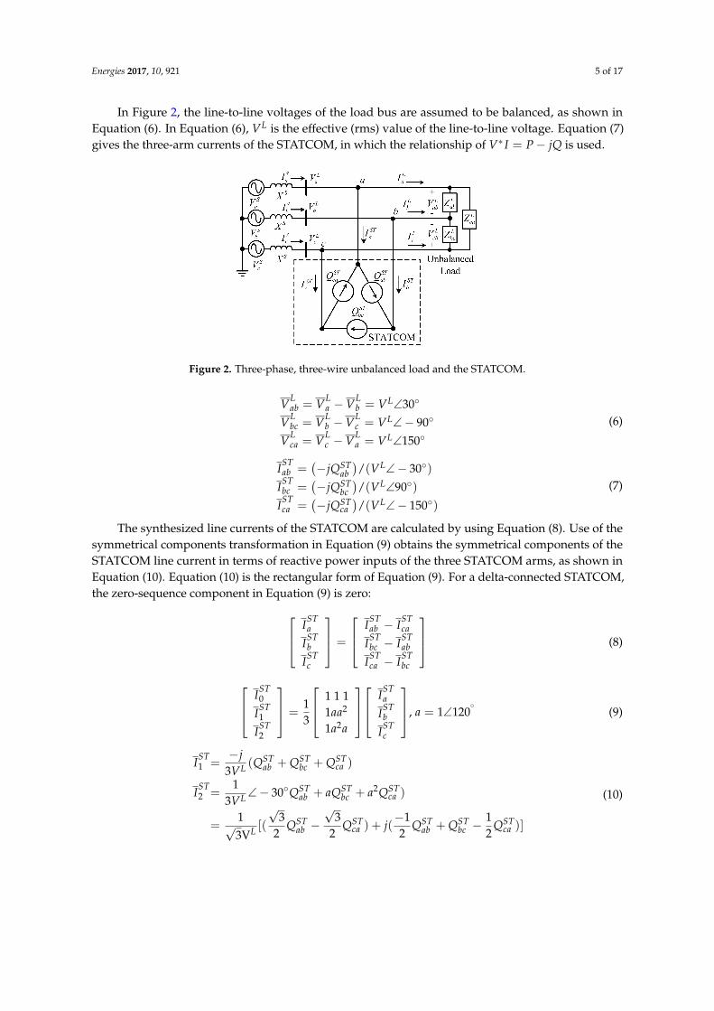
In Figure 2, the line-to-line voltages of the load bus are assumed to be balanced, as shown inEquation (6). In Equation (6), VL is the effective (rms) value of the line-to-line voltage. Equation (7)gives the three-arm currents of the STATCOM, in which the relationship of V∗ I = P− jQ is used.
Figure 2. Three-phase, three-wire unbalanced load and the STATCOM.
VLab = VL
a −VLb = VL∠30
VLbc = VL
b −VLc = VL∠− 90
VLca = VL
c −VLa = VL∠150
(6)
ISTab =
(−jQST
ab)/(VL∠− 30)
ISTbc =
(−jQST
bc)/(VL∠90)
ISTca =
(−jQST
ca)/(VL∠− 150)
(7)
The synthesized line currents of the STATCOM are calculated by using Equation (8). Use of thesymmetrical components transformation in Equation (9) obtains the symmetrical components of theSTATCOM line current in terms of reactive power inputs of the three STATCOM arms, as shown inEquation (10). Equation (10) is the rectangular form of Equation (9). For a delta-connected STATCOM,the zero-sequence component in Equation (9) is zero: IST
a
ISTb
ISTc
=
ISTab − IST
ca
ISTbc − IST
ab
ISTca − IST
bc
(8)
IST0
IST1
IST2
=13
1 1 11aa2
1a2a
IST
a
ISTb
ISTc
, a = 1∠120
(9)
IST1 =
−j3VL (Q
STab + QST
bc + QSTca )
IST2 =
13VL ∠− 30QST
ab + aQSTbc + a2QST
ca )
=1√3VL [(
√3
2QST
ab −√
32
QSTca ) + j(
−12
QSTab + QST
bc −12
QSTca )]
(10)

Energies 2017, 10, 921 6 of 17
Use of the two-wattmeter method for the unbalanced load obtains the symmetrical componentsof the load current. Equation (11) is the line-to-line powers flowing to the load. From Equation (11),the symmetrical components of the load current are shown in Equation (12):
(VLab)(IL
a )∗= VL∠30[(IL
1 )∗ + (IL
2 )∗]
(VLcb)(IL
c )∗= −a2VL∠30[a2(IL
1 )∗ + a(IL
2 )∗]
(11)
[IL
1
IL2
]=−1√3VL
[−1 −1a2 1
][(VL
ab)∗(IL
a )
(VLcb)∗(IL
c )
](12)
where,(VL
ab)∗(IL
a ) = PLab − jQL
ab(VL
cb)∗(IL
c ) = PLcb − jQL
cb
From the two-wattmeter method, use of Equation (13) calculates the three-phase active andreactive powers to the load. The three-phase powers from the power source can be obtained bya similar calculation. The symmetrical components of the load current in Equation (12) are rearrangedas a rectangular form, as shown in Equation (14). For unbalanced load compensation, the STATCOMshould eliminate the imaginary part of the positive-sequence component and total negative-sequencecomponent of the load current, as shown in Equation (15):
PL3φ = PL
ab + PLcb, QL
3φ = QLab + QL
cb (13)
IL1=
1√3VL
[(PLab + PL
cb)− j(QLab + QL
cb)]
IL2=
1√3VL
[(12
PLab − PL
cb +
√3
2QL
ab) + j(−12
QLab + QL
cb +
√3
2PL
ab)]
(14)
Im
IL1
+ IST
1 = 0, IL2 + IST
2 = 0 (15)
Finally, combining Equations (10), (14) and (15) gives the needed reactive power of each STATCOMarm for real-time load compensation, as shown in Equation (16). The load compensation formulain Equation (16) is very compact and suitable for the delta-connected STATCOM. The sizing of theSTATCOM is easy by using Equation (16). With only few power transducers, the compensation formulais implemented easily:
QST∗ab = −QL
ab +1√3
PLcb
QST∗bc = −QL
cb −1√3
PLab
QST∗ca =
1√3
PLab −
1√3
PLcb
(16)
With the STATCOM compensation, the source current only contains real part of thepositive-sequence load current, as shown in Equation (17). As a result, the source current is balancedwith unity power factor, as shown in Equation (18). A systematic design approach regarding the loaddemand, the sizing of the STATCOM, and the power source response is completed by using Equations(13), (16) and (18):
IS1 = ReIL
1 =PL
ab + PLcb√
3VL∠0, IS
2 = IS0 = 0 (17)
ISa
ISb
ISc
=
1 1 11a2a1aa2
0
PLab+PL
cb√3VL
0
=
1a2
a
(PLab + PL
cb√3VL
)=
IS∠0
IS∠− 120
IS∠120
, IS =PL
ab + PLcb√
3VL(18)

Energies 2017, 10, 921 7 of 17
3.2. The Proposed STATCOM Controller
Figure 3a presents the architecture of the proposed STATCOM controller. Use of Equation (16)calculates the reactive power commands of the three STATCOM arms, QST∗
ab , QST∗bc , and QST∗
ca , inreal-time. First, the controller detects the line currents (iL
a , iLc ) and line-to-line voltages (vL
ab, vLcb) of the
unbalanced load to obtain the active and reactive powers (PLab, QL
ab, PLcb, QL
cb) to the load. A DSP-basedpower data detector is employed in the calculation. Three proportional-integral-derivative (PID)feedback controllers regulate the reactive power of the three STATCOM arms, independently. Forexample, the actual reactive power input QST
ab of the STATCOM arm a-b is detected and then comparedwith the needed reactive power QST∗
ab . With the compared result, the PID controller generates theinternal angle command δST∗
ab . For prevention of over-current operation during system faults, internalangle limiters are installed in the outputs of the PID controllers. Finally, the internal angle commandδST∗
ab produces the switching signals for the FHB cells according to Figure 1b. Three phase-locked loops(PLLs) generate reference signals for synchronizing switching patterns to FHB cells of each STATCOMarm, respectively.
Figure 3. The proposed STATCOM controller and gating sequence (a) The STATCOM controller;(b) Alternate swapping of switching patterns for dc-link voltages balancing.
A fast powers detection method is needed for the real-time compensation scheme in Figure 3a.Figure 4 shows the fast active and reactive powers calculation block for the STATCOM controllerby using the single-phase α− β reference frame method [34]. With the fast calculation method, theneeded load powers for Equation (16) and the reactive power inputs of the three STATCOM arms arecalculated in real-time. This accelerates the response of the STATCOM.

Energies 2017, 10, 921 8 of 17
Figure 4. The fast power calculation block.
During the STATCOM operation, the switching signals θ1~θ3 for the three FHB cells in eachSTATCOM arm are swapped in each period of fundamental frequency, as shown in Figure 3b. Thealternate swapping control of the switching signals can balance the dc-link voltages of FHB cells ineach STATCOM arm without using additional dc voltage feedback control [35]. Furthermore, usingstep modulation in Figure 3b significantly reduces switching losses, and the switching devices mainlyhave conducting loss. Therefore, the operation efficiency of the STATCOM main circuit can reach99%, which is much higher than other types of multilevel STATCOMs using high frequency switchingtechniques [36]. With the proposed controller in Figure 3, the STATCOM regulates reactive powerinputs of its three arms independently for real-time load compensation.
4. Simulation Results
Figure 5 depicts the STATCOM simulation system constructed in the MatLab/Simulink program.The STATCOM main circuit is a transformerless, delta-connected configuration, as shown in Figure 1a.A single-phase load controlled by a switch creates unbalanced operation, which tests the transient andsteady state compensation effects of the STATCOM. The sampling time of the STATCOM controlleris set at 0.52 ms, which is equivalent to 32 sampling points in a period of fundamental frequency(60 Hz). The parameters of the three PID controllers in Figure 3a are designed on-line using a sequentialapproach with three steps to optimize the system step response, starting with the proportional, integraland derivative gains set to zero: (1) Increase the proportional gain KP to get a stable response witha steady-state error; (2) Then, the integral gain KI is increased gradually for eliminating the steady-stateerror; (3) Finally, careful choice of the derivative gain KD improves the transient response performance.Another useful on-line designing approach for PID controller cab be seen in [37].
Figure 5. STATCOM simulation system.
Use of the assigned sampling time (0.52 ms) digitizes the parameters of the three analog PIDcontrollers for the STATCOM in the simulation. Furthermore, the design results are also used asreference in the hardware implementation. The parameters selection of the two power components,the reactor XST and the dc-link capacitor, significantly affects the transient response characteristicsof the STATCOM. For example, decreasing the capacitance of the dc-link capacitor accelerates the
Energies 2017, 10, 921 9 of 17
response time of the STATCOM; however, this also amplifies the dc-link voltage ripple and increasesthe ac side harmonic current in steady-state operation. Reducing the inductance of the reactor XST
can also accelerate the response time, but the STATCOM control tends to be unstable. A trade-offprocedure obtains the parameters of the two power components. In the paper, the capacitance is set at3300 µF and the inductance is selected as 5 mH, respectively. Appendix A lists the system parametersin Figure 5.
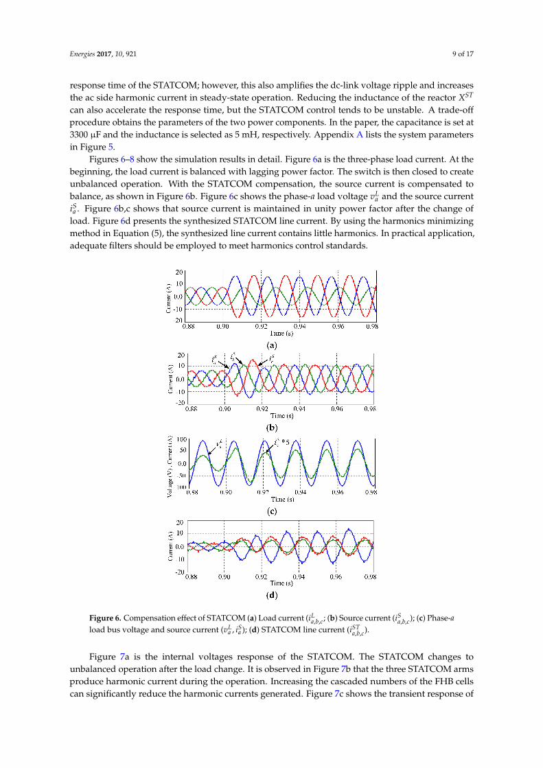
Figures 6–8 show the simulation results in detail. Figure 6a is the three-phase load current. At thebeginning, the load current is balanced with lagging power factor. The switch is then closed to createunbalanced operation. With the STATCOM compensation, the source current is compensated tobalance, as shown in Figure 6b. Figure 6c shows the phase-a load voltage vL
a and the source currentiSa . Figure 6b,c shows that source current is maintained in unity power factor after the change of
load. Figure 6d presents the synthesized STATCOM line current. By using the harmonics minimizingmethod in Equation (5), the synthesized line current contains little harmonics. In practical application,adequate filters should be employed to meet harmonics control standards.
Figure 6. Compensation effect of STATCOM (a) Load current (iLa,b,c; (b) Source current (iS
a,b,c); (c) Phase-aload bus voltage and source current (vL
a , iSa ); (d) STATCOM line current (iST
a,b,c).
Figure 7a is the internal voltages response of the STATCOM. The STATCOM changes tounbalanced operation after the load change. It is observed in Figure 7b that the three STATCOM armsproduce harmonic current during the operation. Increasing the cascaded numbers of the FHB cellscan significantly reduce the harmonic currents generated. Figure 7c shows the transient response of

Energies 2017, 10, 921 10 of 17
the current and voltage, vSTab and iST
ab , in the arm a-b of the STATCOM. According to the compensationformula, the arm a-b absorbs capacitive reactive power after the change of load. Similarly, the armsb-c and c-a absorb inductive and capacitive reactive powers at the same time, respectively. Figure 7dillustrates the dc-link voltages responses of the STATCOM for reference.
Figure 7. Compensation responses of STATCOM (a) STATCOM internal voltage (vSTab,bc,ca; (b) Each arm
current (iSTab,bc,ca); (c) Arm a-b voltage and current (vST
ab , iSTab ); (d) Each arm dc-link voltages responses
(VDCab1,2,3, VDC
bc1,2,3, VDCca1,2,3).
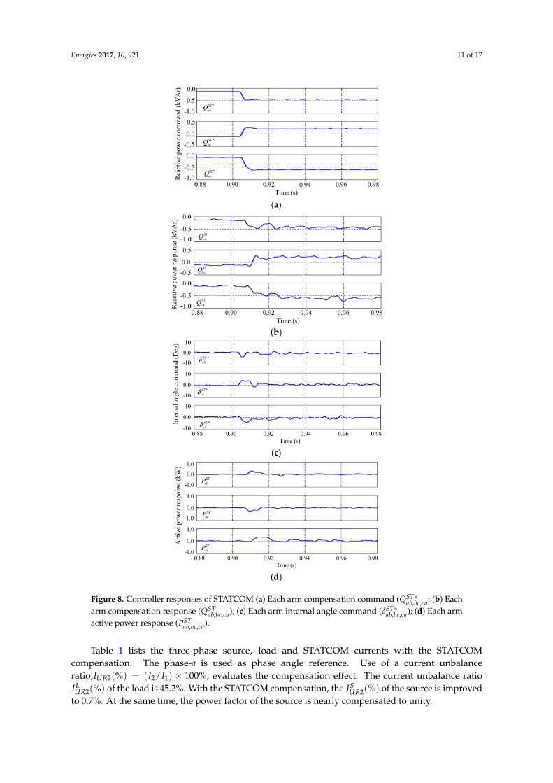
Figure 8 shows the controller responses of the STATCOM in the simulation. Figure 8a presentsthe calculated compensation commands, QST∗
ab , QST∗bc , and QST∗
ca , for each STATCOM arm. In Figure 8b,according to the commands, the STATCOM regulates its reactive power inputs, QST
ab , QSTbc , and QST
ca .Figure 8c shows the dynamic responses of the internal angle commands, δST∗
ab , δST∗bc , and δST∗
ca . Whenthe three arms’ reactive power inputs reach their desired values, the three internal angle commandsgo back to near zero, independently. According to the internal angle commands, the active powerinputs of the three STATCOM arms, PST
ab , PSTbc , and PST
ca , are responded independently, as shown inFigure 8d. The simulation results preliminarily confirm the function of the STATCOM for real-timeload compensation.
Energies 2017, 10, 921 11 of 17
Figure 8. Controller responses of STATCOM (a) Each arm compensation command (QST∗ab,bc,ca; (b) Each
arm compensation response (QSTab,bc,ca); (c) Each arm internal angle command (δST∗
ab,bc,ca); (d) Each armactive power response (PST
ab,bc,ca).
Table 1 lists the three-phase source, load and STATCOM currents with the STATCOMcompensation. The phase-a is used as phase angle reference. Use of a current unbalanceratio,IUR2(%) = (I2/I1) × 100%, evaluates the compensation effect. The current unbalance ratioILUR2(%) of the load is 45.2%. With the STATCOM compensation, the IS
UR2(%) of the source is improvedto 0.7%. At the same time, the power factor of the source is nearly compensated to unity.

Energies 2017, 10, 921 12 of 17
Table 1. Three-phase source, load and STATCOM currents after compensation.
SourceISa IS
b ISc IS
1 IS2 IS
UR2(%)
7.32∠0.15 7.29∠− 120.5 7.23∠120 7.28 0.051 0.7%
LoadILa IL
b ILc IL
1 IL2 IL
UR2(%)10.67∠− 52.3 4.8∠− 145.2 11.48∠103 8.62 3.9 45.2%
STATCOMISTab IST
bc ISTca IST
a ISTb IST
c4.12∠119 1.75∠− 178 5.61∠− 119 8.51∠84.6 3.54∠− 86.2 5.04∠− 102
Note: IUR2(%) = (I2/I1)× 100%, unit: Amp.
Table 2 shows the harmonics analysis results of the three STATCOM arm currents and synthesizedline currents in the simulation when the system goes to a steady-state operation. The 5th and 7th ordersharmonic components are eliminated by using Equation (5). Other higher order harmonic componentsare limited by the reactors XST . The THDs of the source currents are within 6%, and the THDs of theload bus voltages are within 1%, which meet the IEEE-519 harmonic control standard [38]. Table 2 alsoshows that 3th order (zero sequence) harmonic currents circulate among the delta-connected maincircuit. Due to te unbalanced operation of the STATCOM arms, circulating currents (zero sequence oftriple order harmonic currents) do not completely circulate in the delta-connected main circuit loop.Unbalanced operation of the STATCOM generates different amount of 3th order harmonic current ineach arm. Residual 3th order harmonic currents appear in the line currents. Increasing the numbersof the FHB cells in each STATCOM arm and incorporating the 3th order harmonic in the harmonicminimizing method can effectively solve this problem.
Table 2. Harmonics analysis of the STATCOM phases and synthesized lines currents.
Harmonic Orders 1st (A) 3rd (A) 5th (A) 7th (A) 9th (A) 11th (A) 13th (A) THD (%)
Phases
ISTab (n) 3.79 0.88 0.01 0.03 0.36 0.09 0.07 26.27
ISTbc (n) 1.55 0.64 0.03 0.02 0.32 0.10 0.08 51.51
ISTca (n) 4.96 1.03 0.06 0.03 0.31 0.11 0.06 23.19
ISTa (n) 7.57 0.16 0.06 0.07 0.05 0.17 0.11 4.94
LinesISTb (n) 3.24 0.27 0.04 0.03 0.09 0.18 0.11 12.6
ISTc (n) 4.44 0.42 0.04 0.04 0.10 0.15 0.13 11.23
5. Hardware Test Results
Figure 9 shows the hardware test system. Appendix B lists the parameters used in the hardwaresystem. A Y-connected inductive load is connected in parallel with a single-phase load for testing.The STATCOM main circuit is a transformerless configuration with delta connection. Insulation gatebipolar transistor (IGBT) is used as switching elements in the STATCOM main circuit. The controllerof the STATCOM is a TMS320F2812 DSP-based system, in which the sampling time is set at 0.52 ms todigitize the three PID controllers in the DSP. The real-time control program is firstly developed in thehost PC and then downloaded to the DSP-based controller via a JTAG data link. Two eight-channeldigital scopes are employed to measure the transient responses of the STATCOM.
Figures 10 and 11 present the experimental results. Figure 10 shows the current responses ofthe system with the STATCOM compensation. At the beginning of the test, the load is balanced withlagging power factor. Then, the close of the single-phase load creates an unbalanced operation, asshown in Figure 10a. The calculated unbalance ratio of the load current is 45%. With the compensationof the STATCOM, the source current is corrected very quickly to nearly balanced, as shown inFigure 10b. The source current unbalance ratio is improved to 2%. Figure 10c shows the phase-a loadbus voltage vL
a and the source current iSa , in which the source current is maintained in unity power
factor after the load change. Figure 10d is the transient response of the synthesized STATCOM linecurrent. Figure 11 shows other responses of the STATCOM for reference, which are quite agreedwith the simulation results. A comparison between Figures 10d and 11b shows that uses of the

Energies 2017, 10, 921 13 of 17
harmonics minimizing method and the delta-connected STATCOM main circuit significantly eliminatethe harmonic components generated in the three STATCOM arms. The compensation speed of theSTATCOM is quite fast. Although the compensation formula used in the STATCOM is very simple, thecompensation effect is satisfactory. The experimental results verify that the proposed STATCOM issuitable for real-time load balancing and power factor correction.
Energies 2017, 10, 921 13 of 17
quite agreed with the simulation results. A comparison between Figures 10d and 11b shows that uses of the harmonics minimizing method and the delta-connected STATCOM main circuit significantly eliminate the harmonic components generated in the three STATCOM arms. The compensation speed of the STATCOM is quite fast. Although the compensation formula used in the STATCOM is very simple, the compensation effect is satisfactory. The experimental results verify that the proposed STATCOM is suitable for real-time load balancing and power factor correction.
Delta-Connected STATCOM
Lai
Lbi
Lci
SW
LYZ
STabQ
STcaQ
STbcQ
Sai
Sbi
Sci
, ,Sa b cX
, ,Sa b cv Balanced Load
PT
DSPTMS320F2812-Based Controller
Gate D
river
A/D Port
Lav
Lbv
Lcv
CT
LZφ
CTPT
PT
JTAG
Host PC
STai
STbiST
ci
Figure 9. STATCOM hardware test system.
Time (ms)0.0 25 50 75 100 125
0.0
16
-16
Cur
rent
(A
)
150
(a)
Time (ms)0.0 25 50 75 100 125
0.0
16
-16
Cur
rent
(A
)
150
Sai
Sbi
Sci
(b)
Time (ms)0.0 25 50 75 100 125
0.0
100
-100
Vol
tage
(V
) , C
urre
nt (
A)
150
Lav *6.25S
ai
(c)
Time (ms)0.0 25 50 75 100 125
0.0
16
-16
Cur
rent
(A
)
150
(d)
Figure 10. Transient responses with the STATCOM compensation (a) Load current (, ,
La b ci ); (b)
Source current (, ,
Sa b ci ); (c) Phase-a load bus voltage and source current ( ,L S
a av i ); (d) Line current of the
STATCOM (, ,
S Ta b ci ).
Figure 9. STATCOM hardware test system.
Figure 10. Transient responses with the STATCOM compensation (a) Load current (iLa,b,c; (b) Source
current (iSa,b,c); (c) Phase-a load bus voltage and source current (vL
a , iSa ); (d) Line current of the
STATCOM (iSTa,b,c).

Energies 2017, 10, 921 14 of 17
Figure 11. Transient responses of the STATCOM (a) Each arm internal voltage (vSTab,bc,ca; (b) Each
arm current (iSTab,bc,ca); (c) Arm a-b voltage and current (vST
ab , iSTab ); (d) Each arm dc-link voltages
(VDCab1,2,3, VDC
bc1,2,3, VDCca1,2,3).
The proposed phase angle control and step modulation scheme also shows a limitation in theSTATCOM operation. Since the dc-link capacitor voltages need to be regulated frequently for differentneeds of reactive power compensations in the unbalanced load compensations. The charging anddischarging of these dc-link capacitors need more time comparing to STATCOMs using high frequencyPWM techniques. As a result, the response time of the proposed STATCOM is slower than STATCOMsusing PWM controls. However, a high power-efficiency operation can be expected by using phaseangle control and step modulation scheme for a STATCOM. In the planning stage of STATCOM,a trade-off between response time and power efficiency should be made.

Energies 2017, 10, 921 15 of 17
6. Conclusions
A delta-connected, transformerless STATCOM with cascade multilevel FHB converter for real-timeunbalanced load compensation has been studied in the paper. A feedforward compensation formuladerived by using the symmetrical components method in the phasor domain is proposed for theSTATCOM. Both the computer simulation and experimental results show that the proposed STATCOMis very suitable for real-time load compensation. Although the harmonic components in the linecurrent of the STATCOM are not so obvious in the paper, in practical applications, it should beeliminated properly to avoid polluting the power system. The PID controller dominates the transientresponse time of the STATCOM. Further study shows that use of other types of controller, such asadaptive controller based on dynamic STATCOM models, can improve the transient response timein load compensation. Additional functions of the STATCOM, such as voltage support and dampingenhancement of system, can be implemented with properly tuned auxiliary controllers. This paperintroduces a very suitable transition of technology from existing SVC to new-generation STATCOM inhigh power application.
Acknowledgments: The authors would like to thank the Ministry of Science and Technology, Taiwan forthe financial support, project number MOST 104-2221-E-182-029. Valuable comments from the reviewers arealso appreciated.
Author Contributions: Wei-Neng Chang conceived this article and designed the experiments; Ching-Huan Liaoconstructed the software simulation and performed the hardware experiment; all authors wrote the paper.
Conflicts of Interest: The authors declare no conflict of interest.
Nomenclature
GeneralP active powerQ reactive powerv instantaneous voltagei instantaneous currentδ internal angleV voltage phasorI current phasorθ1,θ2,θ3 switching angleZ impedanceX reactancen harmonic orderH() amplitude of fundamental and harmonic componentsS switching functionSuperscriptsS sourceL loadST STATCOMST∗ STATCOM commandDC dc link* complex conjugateSubscripts0, 1, 2 zero-, positive-, negative-componenta, b, c a, b, c phaseab, bc, ca a-b, b-c, c-a line3φ three phaseY Y connectionφ single phase
Energies 2017, 10, 921 16 of 17
Appendix A
Simulation parameters:System side:VS
ll = 110 V , fS = 60 Hz, XSa,b,c = 0.005 Ω, ZL
Y = 12 + j5.48 Ω, ZLφ = 12.1 + j11.34 Ω.
STATCOM side:Cab,bc,ca = 3300 µF, XST
ab,bc,ca = 1.885 Ω (5 mH@60 Hz), KP = 0.475, KI = 0.0095, KD = 0.0011,TSamp = 0.52 ms (for DSP), θ1 = 11.68, θ2 = 31.18, θ3 = 58.58, δMax = +30, δMin = −30.
Appendix B
Hardware parameters:System side:VS
ll = 110 V, fS = 60 Hz, ZLY = 12 + j5.48 Ω, ZL
φ = 12.1 + j11.34 Ω.STATCOM side:Cab,bc,ca = 3300 µF, XST
ab,bc,ca = 1.885 Ω (5 mH@60 Hz), KP = 0.74, KI = 0.012, KD = 0.0013,TSamp = 0.52 ms (for DSP), θ1 = 11.68, θ2 = 31.18, θ3 = 58.58, δMax = +30, δMin = −30.
References
1. Xu, Y.; Tolbert, L.M.; Kueck, J.D.; Rizy, D.T. Voltage and current unbalance compensation using a static varcompensator. IET Power Electron. 2010, 3, 977–988. [CrossRef]
2. Miller, T.J.E. Reactive Power Control in Electric System; Wiley & Sons: New York, NY, USA, 1982.3. Gyugyi, L.; Otto, R.A.; Putman, T.H. Principles and applications of static, thyristor-controlled shunt
compensators. IEEE Trans. Power Appar. Syst. 1978, 97, 1935–1945.4. Chen, J.H.; Lee, W.J.; Chen, M.S. Using a static var compensator to balance a distribution system. IEEE Trans.
Ind. Appl. 1999, 35, 298–304. [CrossRef]5. Wang, J.; Fu, C.; Zhang, Y. SVC control system based on instantaneous reactive power theory and fuzzy PID.
IEEE Trans. Ind. Electron. 2008, 55, 1658–1665. [CrossRef]6. Czarnecki, L.S.; Hsu, S.M.; Chen, G. Adaptive balancing compensator. IEEE Trans. Power Deliv. 1995, 10,
1663–1669. [CrossRef]7. Singh, B.; Saha, R.; Chandra, A.; Al-Haddad, K. Static synchronous compensators (STATCOM): A review.
IET Power Electron. 2009, 2, 297–324. [CrossRef]8. Ghosh, A.; Ledwich, G. Load compensating DSTATCOM in weak AC systems. IEEE Trans. Power Electron.
2003, 18, 1302–1309. [CrossRef]9. Mishra, M.K.; Karthikeyan, K. A fast-acting DC-link voltage controller for three-phase DSTATCOM to
compensate AC and DC loads. IEEE Trans. Power Electron. 2009, 24, 2291–2299. [CrossRef]10. Atalik, T.; Deniz, M.; Koc, E.; Gercek, C.O.; Gultekin, B.; Ermis, M.; Cadirci, I. Multi-DSP and -FPGA-based
fully digital control system for cascaded multilevel converters used in FACTS applications. IEEE Trans. Ind.Inform. 2012, 8, 511–527. [CrossRef]
11. Peng, F.Z.; Lai, J.S.; McKeever, J.W.; VanCoevering, J. A multilevel voltage-source inverter with separate DCsources for static VAr generation. IEEE Trans. Ind. Appl. 1996, 32, 1130–1138. [CrossRef]
12. Lai, J.S.; Peng, F.Z. Multilevel converters-a new breed of power converters. IEEE Trans. Ind. Appl. 1996, 32,509–517.
13. Lee, C.K.; Leung, J.S.K.; Hui, S.Y.R.; Chung, H.S.H. Circuit-level comparison of STATCOM technologies.IEEE Trans. Power Electron. 2003, 18, 1084–1092. [CrossRef]
14. Rodriguez, J.; Lai, J.S.; Peng, F.Z. Multilevel inverters: A survey of topologies, controls, and applications.IEEE Trans. Ind. Electron. 2002, 49, 724–738. [CrossRef]
15. Peng, F.Z.; Lai, J.S. Dynamic performance and control of a static var generator using cascade multilevelinverters. IEEE Trans. Ind. Appl. 1997, 33, 748–755. [CrossRef]
16. Maharjan, L.; Inoue, S.; Akagi, H. A transformerless energy storage system based on a cascade multilevelPWM converter with star configuration. IEEE Trans. Ind. Appl. 2008, 44, 1621–1630. [CrossRef]
17. Sano, K.; Takasaki, M. A transformerless D-STATCOM based on a multivoltage cascade converter requiringno DC sources. IEEE Trans. Power Electron. 2012, 27, 2783–2795. [CrossRef]
Energies 2017, 10, 921 17 of 17
18. Gultekin, B.; Gercek, C.O.; Atalik, T.; Deniz, M.; Bicer, N.; Ermis, M.; Kose, K.N.; Ermis, C.; Koc, E.; Cadirci, I.;et al. Design and implementation of a 154-kV ±50-Mvar transmission STATCOM based on 21-level cascadedmultilevel converter. IEEE Trans. Ind. Appl. 2008, 48, 1030–1045. [CrossRef]
19. Gultekin, B.; Ermis, M. Cascaded multilevel converter-based transmission STATCOM: System designmethodology and development of a 12 kV ±12 MVAr power stage. IEEE Trans. Power Electron. 2013, 28,4930–4950. [CrossRef]
20. Akagi, H. Classification, terminology, and application of the modular multilevel cascade converter (MMCC).IEEE Trans. Power Electron. 2011, 26, 3119–3130. [CrossRef]
21. Peng, F.Z.; Wei, Q.; Dong, C. Recent advances in multilevel converter/inverter topologies and applications.In Proceedings of the 2010 International Power Electronics Conference, Sapporo, Japan, 21–24 June 2010;pp. 492–501.
22. Liu, Z.; Liu, B.; Duan, S.; Kang, Y. A novel DC capacitor voltage balance control method for casca1demultilevel STATCOM. IEEE Trans. Power Electron. 2012, 27, 14–27. [CrossRef]
23. Peng, F.Z.; Wang, J. A universal STATCOM with delta-connected cascade multilevel inverter. In Proceedingsof the 2004 IEEE 35th Annual Power Electronics Specialists Conference, Aachen, Germany, 20–25 June 2004;Volume 5, pp. 3529–3533.
24. Chang, W.N.; Liao, C.H. Real-time load compensation by using a cascaded multilevel inverter-basedSTATCOM. In Proceedings of the 2011 IEEE Ninth International Conference on Power Electronics and DriveSystems, Singapore, 5–8 December 2011; pp. 840–846.
25. Chang, W.N.; Liao, C.H.; Wang, P.L. Unbalanced load compensation in three-phase power system witha current-regulated DSTATCOM based on cascade modular h-bridge converter. J. Mar. Sci. Technol. 2016, 24,484–492.
26. Song, Q.; Liu, W.; Yuan, Z. Multilevel optimal modulation and dynamic control strategies for STATCOMsusing cascaded multilevel inverters. IEEE Trans. Power Electron. 2007, 22, 1937–1946. [CrossRef]
27. Shi, Y.; Liu, B.; Duan, S. Eliminating DC current injection in current-transformer-sensed STATCOMs.IEEE Trans. Power Electron. 2013, 28, 3760–3767. [CrossRef]
28. Hagiwara, M.; Maeda, R.; Akagi, H. Negative-sequence reactive-power control by a PWM STATCOM based ona modular multilevel cascade converter (MMCC-SDBC). IEEE Trans. Ind. Appl. 2012, 48, 720–729. [CrossRef]
29. Du, S.; Liu, J.; Lin, J.; He, Y. A novel DC voltage control method for STATCOM based on hybrid multilevelh-bridge converter. IEEE Trans. Power Electron. 2013, 28, 101–111. [CrossRef]
30. Wu, P.H.; Chen, H.C.; Chang, Y.T.; Cheng, P.T. Delta-connected cascaded H-bridge converter application inunbalanced load compensation. IEEE Trans. Ind. Appl. 2017, 53, 1254–1262. [CrossRef]
31. Schauder, C.; Menhta, H. Vector analysis and control of advanced static VAR compensators. IEE Proc. CGener. Transm. Distrib. 1993, 140, 299–306. [CrossRef]
32. Sirisukprasert, S.; Lai, J.S.; Liu, T.H. Optimum harmonic reduction with a wide range of modulation indexesfor multilevel converters. IEEE Trans. Ind. Electron. 2002, 49, 875–881. [CrossRef]
33. Liu, Y.; Hong, H.; Huang, A.Q. Real-time calculation of switching angles minimizing THD for multilevelinverters with step modulation. IEEE Trans. Ind. Electron. 2009, 56, 285–293. [CrossRef]
34. Chang, W.N.; Pon, W.H.; Yeh, K.D. Digital design and implementation of fast power data detector.In Proceedings of the IEEE International Conference of Power Electronics and Drive Systems (PEDS’2001),Denpasar, Indonesia, 25–25 October 2001; Volume 200, pp. 623–627.
35. Peng, F.Z.; McKeever, J.W.; Adams, D.J. A power line conditioner using cascade multilevel inverters fordistribution systems. IEEE Trans. Ind. Appl. 1998, 34, 1293–1298. [CrossRef]
36. Tolbert, L.M.; Peng, F.Z.; Habetler, T.G. Multilevel converters for large electric drives. IEEE Trans. Ind. Appl.1999, 35, 36–44. [CrossRef]
37. Rashid, M.H. Power Electronics Handbook: Devices, Circuits, and Applications, 3rd ed.; Elsevier Inc.: Oxford, UK,2011; p. 1049.
38. IEEE Recommended Practices and Requirements for Harmonic Control in Electrical Power Systems;IEEE Std. 519-1992; IEEE: New York, NY, USA, 1993.
© 2017 by the authors. Licensee MDPI, Basel, Switzerland. This article is an open accessarticle distributed under the terms and conditions of the Creative Commons Attribution(CC BY) license (http://creativecommons.org/licenses/by/4.0/).