design and implementation of an autonomous robot for steel
TRANSCRIPT
Design and Implementation of an Autonomous Robotfor Steel Bridge Inspection
Nhan H. Pham and Hung M. La, Senior Member, IEEE
Abstract— Steel bridges constitute the second most bridgesin the U.S. while the number of deficient bridges are growing.Currently, the majority number of current bridge inspectionsare done manually by inspectors which require significantamount of human resources along with expensive and spe-cialized equipment. Moreover, it is difficult and dangerous forinspectors to inspect large bridges with high structures. In thispaper, we propose a new design and implementation of a roboticsystem that can be used for steel bridge inspection. The robotconsists of four magnetic wheels which create adhesion to steelsurface. It is able to carry multiple sensors for navigation andmapping. Collected data are sent to the ground station for livemonitoring as well as further processing. In addition, magneticfield and range sensors are also integrated to enable robot tomove safely on steel surfaces. Results with physical tests on realsteel structures are shown to validate the feasibility of robotdesign.
I. INTRODUCTION
A. Motivation
As the number of infrastructures especially bridges aregrowing which have recently passed 600,000 in the U.S [1].Among more than 200,000 steel bridges, one third of themare either deficient or functionally obsolete which are likelya growing threat to human’s safety. Collapse of numerousbridges recorded over past 15 years has shown significantimpact on the safety of all travelers. In particular, the Min-neapolis I-35W Bridge in Minnesota, U.S collapsed in 2007due to undersized gusset plates, increased concrete surfacingload, and weight of construction supplies/equipment [2].There was a recent report in 2013 related to Scott Cityroadway in Missouri, U.S collapsing two sections of thebridge onto the rail line. These accidents may result frominadequate bridge inspection and maintenance due to largenumber of bridges needed to be taken care of. Hence, therehave been many research to apply advanced technologyincluding robotics to assist human for bridge inspection andmaintenance. However, those activities require great amountof human resources along with expensive and specializedequipment. Currently, most bridge inspections are done byinspectors with visual inspection or using manual methodssuch as hammer tapping and chain dragging for delaminationand corrosion detection which are very time consuming.Moreover, it is really difficult and dangerous to inspectlarge bridges with high structures since inspectors have to
This work is supported by the University of Nevada, Reno and theNational Science Foundation under the grants: NSF-ICorps#1559942.
Nhan Pham and Hung La are with the Advanced Robotics and Au-tomation (ARA) Lab, Department of Computer Science and Engineering,University of Nevada, Reno, NV 89557, USA. Corresponding author: HungLa, email: [email protected].
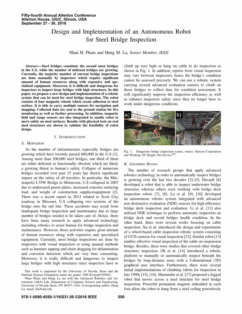
climb up very high or hang on cable to do inspection asshown in Fig. 1. In addition, reports from visual inspectionmay vary between inspectors, hence the bridge’s conditioncannot be assessed precisely. We can use a robotic systemcarrying several advanced evaluation sensors to climb onthose bridges to collect data for condition assessment. Itwill significantly improve the inspection efficiency as wellas enhance inspectors safety since they no longer have towork under dangerous conditions.
Fig. 1. Dangerous bridge inspection scenes, source: Harcon Corporationand Working AT Height Alti-ServiceTM.
B. Literature Review
The number of research groups that apply advancedrobotics technology in order to automatically inspect bridgesis growing over the last two decades [3]–[5]. Devault [6]developed a robot that is able to inspect underwater bridgestructures whereas others were working with bridge deckinspection robots [7], [8]. La et al. [9], [10] developedan autonomous robotic system integrated with advancednon-destructive evaluation (NDE) sensors for high-efficiencybridge deck inspection and evaluation. Li et al. [11] alsoutilized NDE technique to perform automatic inspection onbridge deck and record bridges health condition. In theother hand, there were several works focusing on cableinspection. Xu et al. introduced the design and experimentsof a wheel-based cable inspection robotic system consistingof CCD cameras for visual inspection [12]. Similar robot [13]enables effective visual inspection of the cable on suspensionbridge. Besides, there were studies that covered other bridgestructures inspection. Oh et al. [14] introduced a roboticplatform to manually or automatically inspect beneath thebridges by long-distance users with a 3-dimentional (3D)graphical user interface. Furthermore, there were severalinitial implementations of climbing robots for inspection inlate 1990s [15], [16]. Mazumdar et al. [17] proposed a leggedrobot that moves across a steel structure for steel bridgeinspection. Powerful permanent magnets imbedded in eachfoot allow the robot to hang from a steel ceiling powerlessly
978-1-5090-4550-1/16/$31.00 ©2016 IEEE 556
Fifty-fourth Annual Allerton ConferenceAllerton House, UIUC, Illinois, USASeptember 27 - 30, 2016

while the attractive force is modulated by tilting the footagainst the steel surface. A robot with magnetic wheelswas developed by Wang et al. [18] carrying Giant MagnetoResistive sensor array for crack and corrosion detection. Liuet al. also proposed a bridge inspection method using a wall-climbing robot based on negative pressure adhesion mech-anism which collects crack images with a high-resolutioncamera so that the crack could be extracted and analyzedprecisely [19], [20]. Taking advantage of attraction forcecreated by permanent magnets, Leibbrandt et al. [21] andLeon-Rodriguez et al. [22] developed different wall-climbingrobots carrying NDE devices to detect weld defects, cracks,corrosion testing that is capable of inspecting oil tanks orsteel bridges. San-Millan [23] presented the development of ateleoperated wall climbing robot which can be equipped withvarious testing probes and cameras for different inspectiontasks. Zhu et al. [24] used a magnetic wall-climbing robotcapable of navigating on steel structures, measuring struc-tural vibrations, processing measurement data and wirelesslycommunicating information to investigate field performanceof flexure-based mobile sensing nodes (FMSNs). The FM-SNs were deployed to identify minor structural damage,illustrating a high sensitivity in damage detection enabledby flexible mobile deployment.
In this paper, the design and implementation of a four-wheeled robot for steel bridge inspection is introduced.Taking advantage of adhesion force created by permanentmagnets, the robot is able to move freely on steel surface,carry several sensors for visual crack detection and struc-ture mapping, and wirelessly controlled. With an advancedmechanical design, the robot is able to carry a decent load(approximately 4kg) while climbing on both inclination andupside-down surfaces. The robot can also transition from onesurface to another surface with up to 90 degrees change inorientation. Collected data are sent to a ground station infor real time monitoring and further processing. In addition,magnetic field sensors and range sensors are also integratedto help robot move safely on steel surfaces.
The rest of the paper is organized as follows. SectionII describes the overall robot design. Section III illustratesthe robots control. Section IV shows various experiments toverify robot design and section V gives the conclusion andfuture work.
II. OVERALL DESIGN
A. Mechanical Design
A four motorized wheels robot design is proposed whichtakes advantage of permanent magnets for adhesion forcecreation. Therefore, it allows the robot to adhere to steelsurfaces without consuming any power. In addition, cylindershaped magnets are used for convenience and flexibility inadjusting the attraction force. Moreover, eight high torqueservo motors are modified to use for driving four wheelsand four shafts which are used for robot lifting. The robotsparameters are shown in Table I while motors parameters arelisted in Table II.
TABLE IROBOT PARAMETERS
Length 220.9 mmWidth 130 mmHeight 241.26 mmWeight 14 lbs. (without payload) and 20 lbs. (full load)Drive 4 motorized wheels
Controller Embedded controller + onboard computer
TABLE IIMOTOR PARAMETERS
Torque 525 g/mm (2S Li-Po)Speed 0.12 sec/ 60O (2S Li-Po)
Length 40.13 mmWidth 20.83 mmHeight 39.62 mmWeight 71 gVoltage 6-8.5V (2S Li-Po battery)
Each wheel contains slots which can be filled with upto 36 Neodymium magnet cylinders with poles on flat endsas shown in Fig. 2. This design gives us the flexibility indetermining the amount of magnetic force and helps reducethe weight of the robot. According to on [25], if there isan air gap between magnet cylinders and steel frame, thepull force is greatly affected. Table III and Fig. 3 describethe relationship between magnetic pull force and the air gap.Additionally, four wheels are designed such that the robotcan overcome several situations including transitioning fromone surface to another surface with up to 90 degrees changein orientation or getting rid of being stuck. Additionally, fourshafts have been added in order to lift either front or rearwheels off the ground if the robot is stuck on rough terrainsas shown in Fig. 4.
From this wheel design, there are always either four orfive magnet cylinders which are within 1mm from the steelsurface as shown in Fig. 5. From Table III, the magnetic forcecreated from each wheel can be calculated if 7/16′′×7/16′′
magnet cylinders are used is as following:
Fmagi,i=1,..,4= 50.6 ∗ 2 + 19.6 ∗ 2 = 140.4(N)
orFmagi,i=1,..,4
= 50.6 + 19.6 ∗ 4 = 129(N)
where Fmagi = ‖~Fmagi‖ is the Euclidean norm of ~Fmagi .
TABLE IIIPULL FORCE OVER AIR GAP (7/16” X 7/16” MAGNET)
Distance PullForce (N)
(mm) Magnet tosteel plate
Between twosteel plates
Magnet tomagnet
0 50.6 57.7 50.41 19.6 26.9 29.32 10.8 16.7 20.93 6.5 11.1 15.64 4.1 7.7 125 2.7 5.4 9.56 1.8 3.9 7.57 1.3 2.9 6.18 0.9 2.2 4.99 0.6 1.6 410 0.5 1.3 3.3
557

Fig. 2. Wheels with magnet cylinders.
Fig. 3. Pull force over air gap of 7/16 x 7/16 magnet cylinder.
Therefore, the total magnetic force in theory can be atleast:
∑4i=1(Fmagi) ≥ 129 ∗ 4 = 516(N).
However, each wheel is covered with a 1mm layer of clothto increase the friction with the steel surface. Therefore, thereal magnetic force is calculated as:
Fmagi,i=1,..,4 = 19.6 ∗ 2 + 10.8 ∗ 2 = 60.8(N)
orFmagi,i=1,..,4 = 19.6 + 10.8 ∗ 4 = 62.8(N).
Theoretically, the total magnetic force is at least:
Fmag =4∑
i=1
(Fmagi) ≥ 60.8 ∗ 4 = 243.2(N).
More details in the robots design and first prototype areshown in Fig. 6 and Fig. 7.
Regarding moving on steel surfaces, there are problemsneeded to be addressed in order to maintain stability of therobot which are sliding and turn-over failure as illustrated inFig. 8.
1) Sliding Failure Investigation: In general case, the robotshould be able to climb on different degree of inclinationsurface as shown in Fig. 9.
Where P is the total weight, ~Fmag is the magneticadhesion force, N is the reaction force, µ is the frictionalcoefficient and α is the degree of inclination.
Denote that∑ ~F is the total force applied to the robot and
Fx and Fy are the force’s projected components to x and yaxises as shown in Fig. 9. According to Newton’s SecondLaw of Motion, when the robot stops∑
~F = ~0.
Fig. 4. Two out of four shafts used to lift the robot.
Fig. 5. Wheel design with magnet cylinders.
When the robot is on top of inclined surface as shown inFig. 9.a:∑Fy = P cosα+ Fmag −N = 0⇔ N = P cosα+ Fmag∑Fx = P sinα− µN = 0⇔ N =
P sinα
µ
P cosα+ Fmag =P sinα
µ⇔ Fmag =
P sinα
µ− P cosα.
Therefore, magnetic force should satisfy following conditionto avoid sliding failure
Fmag >P sinα
µ− P cosα. (1)
In case the robot moves on bottom of inclined surface aspresented in Fig. 9.b:∑Fy = P cosα− Fmag +N = 0⇔ N = Fmag − P cosα∑Fx = P sinα− µN = 0⇔ N =
P sinα
µ
Fmag − P cosα =P sinα
µ⇔ Fmag =
P sinα
µ+ P cosα.
Therefore, magnetic force should satisfy
Fmag >P sinα
µ+ P cosα. (2)
In special case when robot moves on a vertical surface(α = 90o)
Fmag >P
µ. (3)
In general, in order to avoid sliding failure, the value ofmagnetic force should satisfy
Fmag > max{P sinα
µ− P cosα;
P
µ;P sinα
µ+ P cosα
}.
(4)
558
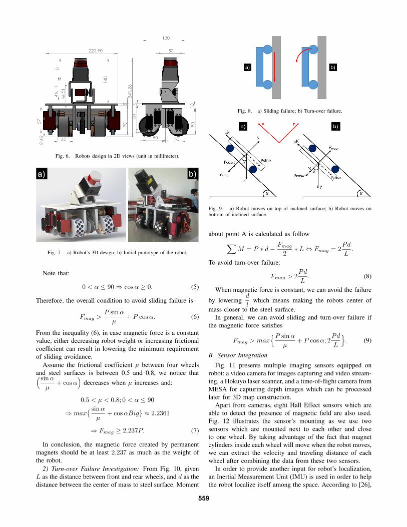
Fig. 6. Robots design in 2D views (unit in millimeter).
Fig. 7. a) Robot’s 3D design; b) Initial prototype of the robot.
Note that:
0 < α ≤ 90⇒ cosα ≥ 0. (5)
Therefore, the overall condition to avoid sliding failure is
Fmag >P sinα
µ+ P cosα. (6)
From the inequality (6), in case magnetic force is a constantvalue, either decreasing robot weight or increasing frictionalcoefficient can result in lowering the minimum requirementof sliding avoidance.
Assume the frictional coefficient µ between four wheelsand steel surfaces is between 0.5 and 0.8, we notice that( sinα
µ+ cosα
)decreases when µ increases and:
0.5 < µ < 0.8; 0 < α ≤ 90
⇒ max{ sinα
µ+ cosαBig} ≈ 2.2361
⇒ Fmag ≥ 2.237P. (7)
In conclusion, the magnetic force created by permanentmagnets should be at least 2.237 as much as the weight ofthe robot.
2) Turn-over Failure Investigation: From Fig. 10, givenL as the distance between front and rear wheels, and d as thedistance between the center of mass to steel surface. Moment
Fig. 8. a) Sliding failure; b) Turn-over failure.
Fig. 9. a) Robot moves on top of inclined surface; b) Robot moves onbottom of inclined surface.
about point A is calculated as follow∑M = P ∗ d− Fmag
2∗ L⇔ Fmag = 2
Pd
L.
To avoid turn-over failure:
Fmag > 2Pd
L. (8)
When magnetic force is constant, we can avoid the failure
by loweringd
lwhich means making the robots center of
mass closer to the steel surface.In general, we can avoid sliding and turn-over failure if
the magnetic force satisfies
Fmag > max{P sinα
µ+ P cosα; 2
Pd
L
}. (9)
B. Sensor Integration
Fig. 11 presents multiple imaging sensors equipped onrobot: a video camera for images capturing and video stream-ing, a Hokuyo laser scanner, and a time-of-flight camera fromMESA for capturing depth images which can be processedlater for 3D map construction.
Apart from cameras, eight Hall Effect sensors which areable to detect the presence of magnetic field are also used.Fig. 12 illustrates the sensor’s mounting as we use twosensors which are mounted next to each other and closeto one wheel. By taking advantage of the fact that magnetcylinders inside each wheel will move when the robot moves,we can extract the velocity and traveling distance of eachwheel after combining the data from these two sensors.
In order to provide another input for robot’s localization,an Inertial Measurement Unit (IMU) is used in order to helpthe robot localize itself among the space. According to [26],
559

Fig. 10. Moment calculation about point A.
Fig. 11. a) USB Camera; b) Hokuyo Laser Scanner; c) MESA depthcamera.
some parameters of the 3DM-GX3-25 IMU are described inTable IV
Besides, the robot has four IR range sensors mounted atfour corners of the robot, which can detect whether there issteel surface underneath. Consequently, an edge avoidancealgorithm can be implemented using this input to make surethat the robot can safely travel on steel surfaces. Table Vshows some features of the IR range sensor [27].
III. ROBOT CONTROL
The robot is controlled by two controllers: a microcon-troller (MCU) based controller handling low-level tasks anda more powerful onboard computer for complex process-ing and communication with ground station. The low-levelcontroller has the capability of receiving commands fromonboard computer via serial connection including motioncontrol, sensors data acquisition. The onboard computer isa NUC Core i3 computer from Intel which is responsible
TABLE IV3DM-GX3-25 IMU PARAMETERS
Attitude heading range 360o about all 3 axesStatic accuracy ±0.5o pitch, roll, heading
Dynamic accuracy ±2.0o pitch, roll, headingLong term drift EliminatedData output rate up to 1000 Hz
TABLE VIR RANGE SENSOR PARAMETERS
Type Sharp GP2Y0A41SK0FDistance measuring range 4 cm to 30 cm (1.5 to 12)
Output type Analog voltageUpdate period 16.5 ± 4 milliseconds
Fig. 12. Hall Effect sensors mount.
for getting video camera and 3D camera images then sendthem to ground station over wireless LAN connection fordata post processing and logging. It also executes the edgeavoidance algorithm with sensors data received from the low-level controller to ensure safe traveling on steel surfaces.
Overall, the structure of the system is shown in Fig. 13and the whole robot is depicted in Fig. 14.
Fig. 13. System architecture.
Fig. 14. Robot prototype with integrated sensors.
While moving on steel surfaces, there can be a circum-stance that the robot moves far away toward the edge ofthe surface which it can fall off. Therefore, an algorithmusing input from IR range sensors is incorporated to preventthis failure. Denote dri(i = 1, ..., 4) as the calibrated rangesbefore robot starts moving, ri(i = 1, ..., 4) as sensor readingcorresponding to sensori and di(i = 1, ..., 4) as traveldistances calculated from Hall Effect sensors. When sensorreading is out of the range between [dri − ε; dri + ε] whereε is a predefined threshold, the robot considers that there isno steel surface below sensori.
560

Algorithm 1: EDGE AVOIDANCE.Input: (dr1, dr2, dr3, dr4), (r1, r2, r3, r4), ε,
(d1, d2, d3, d4)1 for i:=1,4 do2 if only one (ri) /∈ [dri − ε; dri + ε] then3 if i:= front right IR sensor then4 Stop5 Go backward with a distance of 5 cm
(∆di ≈ 3)6 Rotate left when travel distance of either
right wheel reach 3 cm (∆di ≈ 2)7 Keep moving8 Check other sensors and take similar actions9 else
10 stop and wait for commands
IV. EXPERIMENTAL RESULTS
In order to verify the design and assess the performanceof the robot, physical experiments were conducted. The testswas under lab environment on built steel bar structures. Theability of climbing and failure avoidance were evaluatedunder both experiments. During the test, one 2S1P (2 cells)7.4V 5000 milliampere-hour (mAh) and one 3S1P 11.1V5000 mAh batteries are used to power the robot. One laptopwhich can connect to a wireless LAN is used as a groundstation.
Fig. 15. Robot can adhere to steel surfaces in different situations.
Fig. 16. Surface transition experiments: a) Transitions from ground to steelbar; b) Passes a 90o angel obstacle.
Fig. 15 presents various cases when the robot was placedon steel surfaces under different degrees of inclination toensure that the magnetic force is strong enough to adhere tosteel surfaces when the robot does not move. In all cases,the robot showed strong adhesion force without sliding orturn-over failure.
Fig. 17. Robot moves on steel surfaces: a) Without load; b) Full load.
The surface transition ability was also validated in twocases: 1) Robot started from the ground (horizontal plane)and climbed on a steel bar (vertical plane); 2) Robot passed aright angel obstacle. Eventually, the robot successfully wentthrough both cases as illustrated in Fig. 16.
Fig. 18. Robot moves on a bridge-like steel structure with Edge Avoidancealgorithm validation.
Fig. 19. a) Depth image; b) Visual image versus depth image.
Moreover, robot is also capable of vertically moves onsteel surface as shown in Fig. 17 when the robot has no loadand full load. The velocity of the robot is approximately10 centimeters/second. In another test, the robot moves ona constructed steel structures from one end to the otherend. The robot successfully reaches the destination as wellas using lifting mechanism to overcome stuck condition asshown in Fig. 18.
During the test, data collected from both video camera anddepth camera are transmitted over wireless connection to thelaptop acting as ground station. Received data are illustratedin Fig. 19.
V. CONCLUSION AND FUTURE WORK
This work describes the design and implementation of asteel climbing robot which is capable of carrying multiplesensors for steel bridge inspection. Initial prototype is imple-mented and validated to ensure the robot is able to stronglyadhere on steel surfaces in multiple situations. The robot is
561

also able to transition from different surfaces with differentinclination levels. There are several sensors attached on therobots while the collected data are transferred to groundstation for further process. Moreover, various sensors areintegrated to assist the robot’s navigation and localizationprocess.
One important step needed to be done is robot local-ization under steel structures. An approach using visual-inertial odometry is being investigated to support robotautonomous navigation and mapping purposes. Furthermore,implementation of map construction method and on-linevisual crack detection algorithm [28], [29] are also withinour interest based on our recent result [30]. Additionally, acooperative process will be investigated to employ multiplerobots for inspecting a large steel bridge efficiently in whichcooperative control-learning-sensing can be applied [31]–[33].
ACKNOWLEDGMENT
The authors would like to thank Sy. N. Dang, Anh Q.Pham, Anh H. Vo and Quang H. Dinh from Duy TanUniversity, Vietnam, for their help and support of the robotimplementation.
REFERENCES
[1] U.S Department of Transportation Federal High-way Administration. National bridge inventory data.http://www.fhwa.dot.gov/bridge/nbi.cfm.
[2] Minnesota Department of Transportation. I-35w st. anthony fallsbridge collapse. http://www.dot.state.mn.us/i35wbridge/collapse.html.
[3] N. Gucunski, S. H. Kee, H. M. La, B. Basily, A. Maher, andH. Ghasemi. Implementation of a fully autonomous platform forassessment of concrete bridge decks rabit. Structures Congress,Portland, Oregon, USA, pages 367–378, 2015.
[4] H. M. La, N. Gucunski, S. H. Kee, J. Yi, T. Senlet, and L. Nguyen.Autonomous robotic system for bridge deck data collection andanalysis. IEEE Inter. Conf. on Intelligent Robots and Systems (IROS),Chicago, Illinois, USA, pages 1950–1955, 2014.
[5] H. M. La, R. S. Lim, B. B. Basily, N. Gucunski, J. Yi, A. Maher,F. A. Romero, and H. Parvardeh. Autonomous robotic system forhigh-efficiency non-destructive bridge deck inspection and evaluation.IEEE Inter. Conf. on Auto. Sci. and Eng. (CASE), Madison, Wisconsin,USA, pages 1065–1070, 2013.
[6] J.E. DeVault. Robotic system for underwater inspection of bridgepiers. Instrumentation Measurement Magazine, IEEE, 3(3):32–37, Sep2000.
[7] R. S. Lim, H. M. La, Z. Shan, and W. Sheng. Developing a crackinspection robot for bridge maintenance. IEEE Inter. Conf. on Roboticsand Automation (ICRA), Shanghai, China, pages 6288–6293, 2011.
[8] R. S. Lim, H. M. La, and W. Sheng. A robotic crack inspectionand mapping system for bridge deck maintenance. IEEE Trans. onAutomation Science and Engineering, 11(2):367–378, April 2014.
[9] H.M. La, R.S. Lim, B.B. Basily, N. Gucunski, Jingang Yi, A. Ma-her, F.A. Romero, and H. Parvardeh. Mechatronic systems designfor an autonomous robotic system for high-efficiency bridge deckinspection and evaluation. Mechatronics, IEEE/ASME Transactionson, 18(6):1655–1664, Dec 2013.
[10] H.M. La, N. Gucunski, S.-H. Kee, and L.V. Nguyen. Data analysisand visualization for the bridge deck inspection and evaluation roboticsystem. Visualization in Engineering, 3(1):1–16, 2015.
[11] Bing Li, Jing Cao, Jizhong Xiao, Xiaochen Zhang, and Hongfan Wang.Robotic impact-echo non-destructive evaluation based on fft and svm.In Intelligent Control and Automation (WCICA), 2014 11th WorldCongress on, pages 2854–2859, June 2014.
[12] Fengyu Xu and Xingsong Wang. Design and experiments on anew wheel-based cable climbing robot. In Advanced IntelligentMechatronics, 2008. AIM 2008. IEEE/ASME International Conferenceon, pages 418–423, July 2008.
[13] K.H. Cho, H.M. Kim, Y.H. Jin, F. Liu, H. Moon, J.C. Koo, and H. R.Choi. Inspection robot for hanger cable of suspension bridge: Mech-anism design and analysis. Mechatronics, IEEE/ASME Transactionson, 18(6):1665–1674, Dec 2013.
[14] Je-Keun Oh, An-Yong Lee, Se Min Oh, Youngjin Choi, Byung-JuYi, and Hai Won Yang. Design and control of bridge inspectionrobot system. In Mechatronics and Automation, 2007. ICMA 2007.International Conference on, pages 3634–3639, Aug 2007.
[15] R.T. Pack, Jr. Christopher, J.L., and K. Kawamura. A rubbertuator-based structure-climbing inspection robot. In Robotics and Automa-tion, 1997. Proceedings., 1997 IEEE International Conference on,volume 3, pages 1869–1874 vol.3, Apr 1997.
[16] M. Abderrahim, C. Balaguer, A. Gimenez, J.M. Pastor, and V.M.Padron. Roma: a climbing robot for inspection operations. InRobotics and Automation, 1999. Proceedings. 1999 IEEE InternationalConference on, volume 3, pages 2303–2308 vol.3, 1999.
[17] A. Mazumdar and H.H. Asada. Mag-foot: A steel bridge inspectionrobot. In Intelligent Robots and Systems, 2009. IROS 2009. IEEE/RSJInternational Conference on, pages 1691–1696, Oct 2009.
[18] Rui Wang and Y. Kawamura. A magnetic climbing robot for steelbridge inspection. In Intelligent Control and Automation (WCICA),2014 11th World Congress on, pages 3303–3308, June 2014.
[19] Quancai Liu and Yong Liu. An approach for auto bridge inspectionbased on climbing robot. In Robotics and Biomimetics (ROBIO), 2013IEEE International Conference on, pages 2581–2586, Dec 2013.
[20] Yong Liu, Qifan Dai, and Quancai Liu. Adhesion-adaptive control ofa novel bridge-climbing robot. In Cyber Technology in Automation,Control and Intelligent Systems (CYBER), 2013 IEEE 3rd AnnualInternational Conference on, pages 102–107, May 2013.
[21] A. Leibbrandt, G. Caprari, U. Angst, R.Y. Siegwart, R.J. Flatt, andB. Elsener. Climbing robot for corrosion monitoring of reinforcedconcrete structures. In Applied Robotics for the Power Industry(CARPI), 2012 2nd International Conference on, pages 10–15, Sept2012.
[22] H. Leon-Rodriguez, S. Hussain, and T. Sattar. A compact wall-climbing and surface adaptation robot for non-destructive testing. InControl, Automation and Systems (ICCAS), 2012 12th InternationalConference on, pages 404–409, Oct 2012.
[23] A. San-Millan. Design of a teleoperated wall climbing robot foroil tank inspection. In Control and Automation (MED), 2015 23thMediterranean Conference on, pages 255–261, June 2015.
[24] Dapeng Zhu, Jiajie Guo, Chunhee Cho, Yang Wang, and Kok-MengLee. Wireless mobile sensor network for the system identification ofa space frame bridge. Mechatronics, IEEE/ASME Transactions on,17(3):499–507, June 2012.
[25] Inc K&J Magnetics. Original magnet calculator.https://www.kjmagnetics.com/.
[26] MicroStrain. 3dm-gx3-25 imu. http://www.microstrain.com/.[27] Sharp. GP2Y0A41SK0F IR rangefinder. http://www.sharp-
world.com/.[28] T. H. Dinh, Q. P. Ha, and H. M. La. Computer vision-based method
for concrete crack detection. In Proceedings of the 14th InternationalConference on Control, Automation, Robotics and Vision (ICARCV),November 13-15, 2016, Phuket, Thailand., pages 1–7, 2016.
[29] P. Prasanna, K. J. Dana, N. Gucunski, B. B. Basily, H. M. La,R. S. Lim, and H. Parvardeh. Automated crack detection on concretebridges. IEEE Transactions on Automation Science and Engineering,13(2):591–599, April 2016.
[30] N.H. Pham, H.M. La, Q.P. Ha, S.N. Dang, A.H. Vo, and Q.H. Dinh.Visual and 3d mapping for steel bridge inspection using a climbingrobot. In The 33rd International Symposium on Automation andRobotics in Construction and Mining (ISARC), pages 141–149, July2016.
[31] H. M. La and W. Sheng. Distributed sensor fusion for scalar fieldmapping using mobile sensor networks. IEEE Trans. on Cybernetics,43(2):766–778, Apr. 2013.
[32] H. M. La, W. Sheng, and J. Chen. Cooperative and active sensingin mobile sensor networks for scalar field mapping. IEEE Trans.on Systems, Man and Cybernetics, Part A: Systems, 45(1):1–12, Jan.2015.
[33] H. M. La, R. Lim, and W. Sheng. Multi-robot cooperative learningfor predator avoidance. IEEE Trans. on Control Systems Technology,23(1):52–63, Jan 2015.
562